manuals.online logo
Brands
  1. Home
  2. •
  3. Brands
  4. •
  5. MRP
  6. •
  7. Bicycle Accessories
  8. •
  9. MRP LOOP TR User manual

MRP LOOP TR User manual

MAINTENANCE DESCRIPTION FREQUENCY
(in hours)
REPLACE BATH OIL
NORMAL CONDITIONS:
50
MUDDY CONDITIONS:
30
REPLACE WIPER SEALS
NORMAL CONDITIONS:
100
MUDDY CONDITIONS:
75
CHECK AIR SPRING AND RELUBE IF NEEDED 50
CHANGE DAMPER OIL 200
CHECK FASTENERS 30
CHECK AIR PRESSURE 30
INSPECT STANCHIONS EVERY RIDE
CLEAN DIRT AND MUD FROM STANCHIONS EVERY RIDE
CHECK ADJUSTMENT CONTROLS EVERY RIDE
SUGGESTED MAINTENANCE INTERVALS
TORQUE VALUES
FASTENER TORQUE
COMPRESSION BOLT (DAMPER SIDE) 70-75 LB-IN 8 NM
COMPRESSION BOLT (AIR SPRING SIDE) 70-75 LB-IN 8 NM
REGISTER YOUR FORK ONLINE AT MRPBIKE.COM
A link to registration can be found under the “SUPPORT” heading. While
there check out our “TECH RESOURCES” section for more information
on the tuning, maintenance, and the technology found in your MRP fork.
MRP IS A DIVISION OF:
MOUNTAIN RACING PRODUCTS
580 N WESTGATE DR
GRAND JUNCTION, CO 81505
970.241.3518
GET THE LATEST INFO ON MRP PRODUCTS
Follow us on:
Facebook.com/MRPbike
Instagram.com/MRPbike
OWNER’S
MANUAL
LOOP
TR & SL
IMPORTANT CONSUMER SAFETY INFORMATION
WARNING: RIDING A BIKE IS DANGEROUS. NOT PROPERLY
MAINTAINING OR INSPECTING YOUR BIKE AND ITS
COMPONENTS IS EVEN MORE DANGEROUS. IT IS ALSO
DANGEROUS TO NOT READ AND FOLLOW THESE
INSTRUCTIONS.
Thank you for choosing MRP. This owner’s manual is your
reference guide to using and fine-tuning your suspension fork
for optimum performance and comfort. It also provides important
information about the proper maintenance of your fork. Carefully
read this manual before installing your fork. If you need further
assistance, our experienced team is able to advise and assist you
to find the exact set up to meet your personal needs.
The fork is an important part of your mountain bike and
this owner’s manual explains how to install and use it properly.
We recommend that it be installed by a qualified bicycle
mechanic. Improperly installed forks might cause serious harm
to you and may severely damage your mountain bike. Never
take any chances with your safety. Before installing and using
your new fork, carefully read this owner’s manual to learn the
correct installation and adjustment procedures and avoid the
consequences of an incorrect installation or improper adjustment.
When your fork requires an oil change or other internal
maintenance, MRP and experienced suspension service centers
are best qualified to provide the necessary service or repairs.
FORK INSTALLATION
1. Remove your old fork from the bicycle. Measure the diameter and
length of your old fork’s steerer tube to ensure that your new steerer
tube is the correct diameter and sucient length for the installation.
If your MRP fork has a tapered steerer tube, be sure to leave enough
room above the taper to allow for proper stem installation.
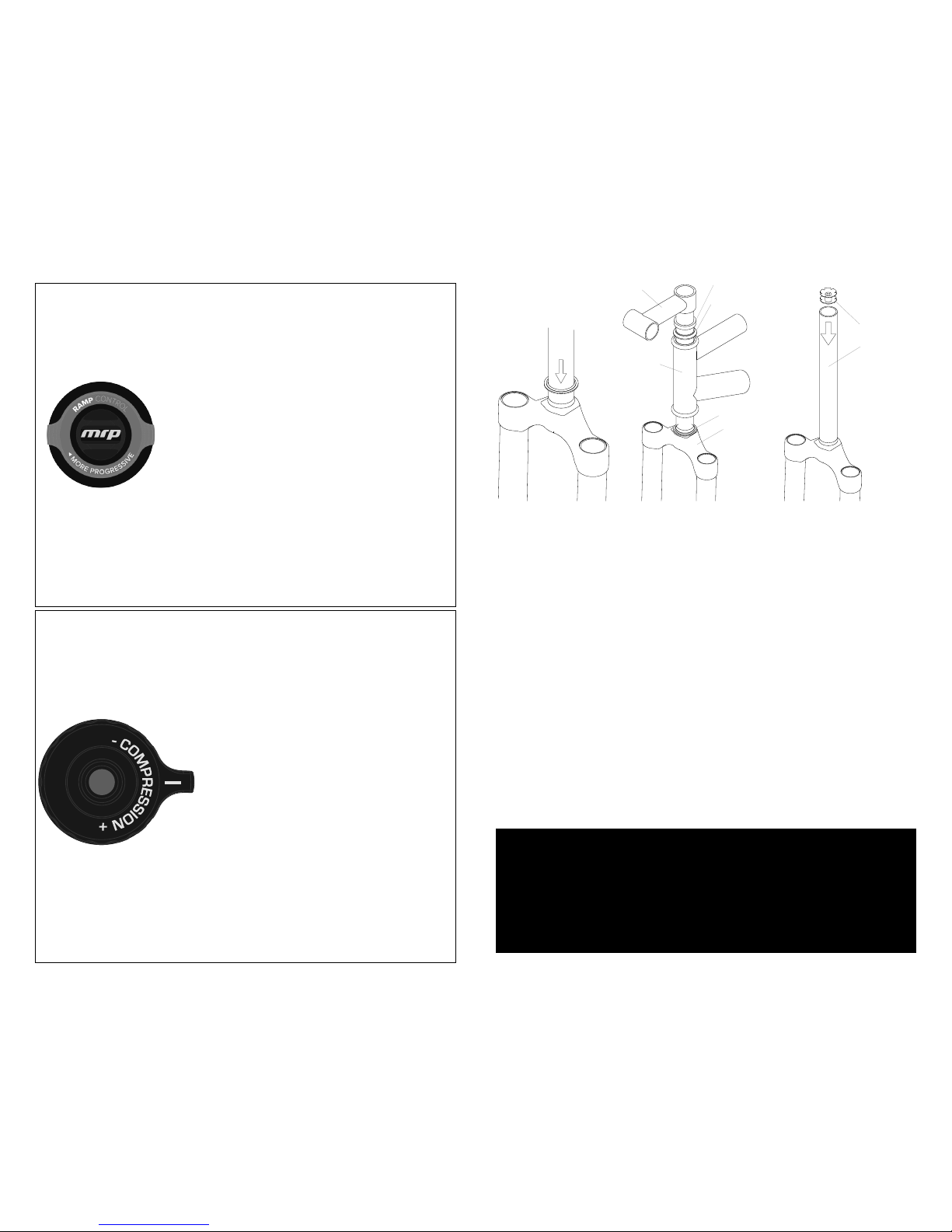
2. Remove the crown race from your old fork.
3. Press the crown race onto your new fork. (See Figure #1)
4. Preassemble the fork on the bike with the headset, stem, and spacers
(optional). Refer to your stem manufacturer’s instructions to determine
how much room is needed to clamp the stem.
5. Mark the steerer tube at the top of the stem. The steerer tube will now
need to be cut to the correct length. Disassemble and cut 3mm (1/8”)
below the mark. Consult your dealer or mechanic if you don’t have the
proper tools to cut the steerer tube.
WARRANTY:
MRP suspension products are the highest quality and as such are
warranted to be free from defects in materials and workmanship
for a period of one year from the date of purchase for the original
purchaser. If date of purchase cannot be verified by product
registration or proof of purchase then the warranty is one year from
the date of manufacture. On receipt of the product by MRP, if it is
found to be defective, MRP will determine replacement or repair of the
product at its sole discretion. MRP shall not be liable for any indirect,
special or consequential damages. Warranty does not apply to any
product that has been installed improperly or adjusted using methods
not outlined in this manual. Warranty also does not cover products
that have been misused or products that have missing/altered serial
numbers. This warranty does not cover breakage or damage that
may result from crashes, falls, or abuse. Normal wear and tear items
such as; seals, wipers, bushings, stanchion coating, stanchions, piston
bands, foam rings, bottom out and top out bumpers, or damage
caused by lack of proper maintenance as outlined in this manual is not
covered by this warranty.
What to do if you need warranty inspection or service:
1. Go to MRPbike.com and locate the warranty contact form in the
support section of the site. Alternatively, call or email MRP (info@
mrpbike.com) about the troubles you are having and to set up a RA#
(Return Authorization Number).
2. Carefully pack and ship your product, be sure to insure the package in
case it is lost or damaged in transit. Clearly write the RA number on the
outside of the box. (Only the return shipping to the customer is covered
under warranty)
MAINTENANCE LOG
DATE PROCEDURE
6. The star fangled nut must now be installed into the steer tube. If you
don’t have the set tool, we recommend dealer installation of this part.
(See Figure #3)
7. Clean and grease all headset bearings and races to prepare them
for assembly. Note: Replace the bearings if there is any sign of wear or
corrosion.
8. Now loosely assemble the headset, stem and handle bars as done in
step four.
9. Install the headset according to the manufacturer’s instructions until
there is no play and the fork turns smoothly.
10. Install your front brake and adjust according to the manufacturer’s
instructions.
11. Install the wheel on the fork. Proper installation of the QtapeR axle is
communicated in the next section of this manual.
12. Check to see that the brakes are adjusted and properly working.
Make sure that the brake cable does not interfere with any part of the
bike and is secured under the brake hose clamp on the fork brace.
Make sure your brakes are adjusted and functioning properly, and the
brake hose does not interfere with any part of the bike when the fork is
compressed and released.
IMPORTANT BRAKE INFORMATION:
THE LOOP FORK FEATURES A POST MOUNT FOR 160mm ROTORS.
SHOULD YOU WANT TO USE A LARGER ROTOR, MAKE SURE TO USE
THE APPROPRIATE DISC BRAKE ADAPTOR AS RECOMMENDED BY
YOUR BRAKE MANUFACTURER. FAILURE TO DO SO COULD RESULT IN
SERIOUS INJURY OR DEATH.
S ta r F a ngled N ut
S teerer T ube
S teering S t r
F ra m
Hea
em O ptional H ea ds et S pac e
Hea dset U pper R ace
e with
ds et C ups
Hea dset L ower R a ce
F ork C rown
RAMP CONTROL (LOOP TR ONLY)
The Ramp Control unit is located within the air spring assembly, and
adjusted via a 16-position knob on the top of the spring-side fork leg. Your
fork comes from the factory tuned 5 clicks from the open, most linear
position. Clockwise adjustment of the knob will reduce the fork’s tendency
to bottom-out on hard hits and increase the ending-stroke spring curve.
Ramp Control gives you the ability to
adjust, on-the-fly, the air spring’s ending-stroke
curve. Ramp Control is completely independent
of your damper or air spring pressure settings.
All MRP forks feature super-supple small-bump
compliance, but with Ramp Control you can set
your fork up to be super plush but still resist
bottoming. Cadillac-plushness not your thing? Dial back the Ramp
Control and up your pressure to enjoy a more linear fork that rides high
but uses every inch of travel eectively.
Adjusting your Loop TR to 8 or more clicks of Ramp Control will
help you stay in control on particularly steep or fast trails by preserving
the last portion of the stroke for big hits and keeping your bike’s
geometry relaxed.
COMPRESSION
The compression adjustment knob is located on the top of the damper-side
fork leg. There are 8 positions of adjustment on the Loop TR and 3 postions
on the Loop SL.
that is subtle, and often overlooked, but
can make a big dierence in how your
fork performs. Aggressive riders tend to
like more compression damping because
it provides a firmer, more positive feel.
Comfort oriented, less aggressive riders
tend to like less because it allows more
small bump sensitivity. Do not confuse
compression damping with spring rate
(air pressure). They are very dierent adjustments, and while adding
compression damping may make the fork feel “stier”, it is not changing
the spring rate.
In the eighth, final position of the compression adjustment range
our hydraulic valving provides a highly-damped, supported feel perfect
for smooth trails, road stretches and transfer stages.
As you turn the dial clockwise, you are adding compression
damping or slowing the forks compression stroke. It is an adjustment
FIGURE 1
FIGURE 2
FIGURE 3
Rebound damping is what prevents
your suspension fork from feeling like a pogo
stick. It controls the rebound stroke of the
fork after a compression stroke (bump) has
occurred. Increasing (turn knob clockwise)
rebound damping slows the rebound stroke
of the fork. Decreasing (turn knob counter
clockwise) rebound damping speeds up the
rebound stroke of the fork. Ideally, you want
to arrive at a setting that allows your wheel to
track the terrain and not get bounced o line. In
the chart to the right you’ll see a recommended
rebound starting point. Utilize this starting point
by turning the rebound knob fully clockwise
then turning it back counter-clockwise until you
reach the desired number of “clicks”.
INSTALLING WHEEL
1. Seat hub into the dropouts of the fork.
2. Insert axle through the disc brake side dropout, through the hub
and into the captive nut on the non-disc brake side dropout.
3. Thread axle into the captive nut by turning the axle or the nut in a
clockwise direction. Position the quick release lever so that when
closed, it’s parallel with the fork
leg and pointing upwards.
4. When you can feel tension on the
quick release cam when the lever
is pointing straight out from the
axle (90 degrees from the fork
leg), you’ve reached the correct
starting point tension. If you don’t
feel the cam start to tension at the
90-degree point, more tension
is needed. You should not have
to strain to close the lever, but it
should close firmly.
IMPORTANT:
DO NOT LUBRICATE AXLE PARTS
REMOVING WHEEL
1. Open the quick release lever all the way. Because the QtapeR
system’s tapered wedges grip very tightly to the dropouts and the
axle, it’s normal for the tapered wedges to occasionally remain in
their seated position when you open the quick release lever. Should
this happen, apply a light tap on the side of the tire with the heel of
your palm. This allows the tapered wedges to release.
2. Unthread the axle (counter clockwise rotation) and pull it out from
the disc brake side.
TENSION BEGINS AT 90°
FULLY CLOSED
The QtapeR-15 axle operates in a similar manner to a traditional quick release
skewer. It’s patent pending tapered wedge interface grips both the axle and
fork lowers. This provides you with an extremely sti fork that steers very
accurately.
OPERATING THE QTAPER AXLE
IMPORTANT:
WHEN INSTALLING THE WHEEL OR A NEW TIRE, CHECK FOR
MINIMUM CLEARANCE. RELIEVE AIR PRESSURE IN THE AIR SPRING
AND COMPRESS FORK COMPLETELY TO BOTTOM OUT. THERE MUST
BE 1/8” OR 3MM CLEARANCE BETWEEN THE CROWN AND HIGHEST
POINT ON THE TIRE AT FULL BOTTOM OUT TO ENSURE ADEQUATE
CLEARANCE IN ALL RIDING CONDITIONS.
AIR PRESSURE FILL PROCEDURE
1. Unthread and remove the negative air chamber cap found on the
bottom of the spring leg.
2. Attach a high-pressure, suspension specific pump to the valve and
using the pump’s bleed button, remove all pressure. Remove the pump.
3. Locate the positive air chamber cap at the top of the spring leg.
Unthread and remove the positive air chamber cap and attach a high-
pressure suspension specific pump to the valve.
4. Fill the positive air chamber to the desired pressure (a chart can be
found below). Remove the pump and re-install the positive air chamber
cap.
5. Return to the negative air chamber; attach the pump, fill to the
desired pressure, remove the pump, and re-install the negative air
chamber cap.
RECOMMENDED AIR PRESSURE SETTINGS
REBOUND

This manual suits for next models

1

Other MRP Bicycle Accessories manuals

MRP SXg User manual

MRP

MRP SXg User manual

MRP G3 Steel User manual

MRP

MRP G3 Steel User manual

MRP BAXTER User manual

MRP

MRP BAXTER User manual

MRP raven User manual

MRP

MRP raven User manual

MRP bartlett User manual

MRP

MRP bartlett User manual

MRP ribbon User manual

MRP

MRP ribbon User manual

MRP S4 User manual

MRP

MRP S4 User manual

MRP hazzard User manual

MRP

MRP hazzard User manual

MRP D-Mount 1x User manual

MRP

MRP D-Mount 1x User manual

Popular Bicycle Accessories manuals by other brands

Specialized Globe Haul ST Wheel Protector Assembly guide

Specialized

Specialized Globe Haul ST Wheel Protector Assembly guide

lifeBeam Cycling Helmet quick start guide

lifeBeam

lifeBeam Cycling Helmet quick start guide

VDO M2WL Installation/operating

VDO

VDO M2WL Installation/operating

Cycplus M2 user manual

Cycplus

Cycplus M2 user manual

blackburn Delphi manual

blackburn

blackburn Delphi manual

Lecyclo 8003T Owners manual instructions

Lecyclo

Lecyclo 8003T Owners manual instructions

Formula 4 Racing operating manual

Formula

Formula 4 Racing operating manual

carado Bike Carrier Assembly instruction

carado

carado Bike Carrier Assembly instruction

AddBike U-Cargo user guide

AddBike

AddBike U-Cargo user guide

Vision TriMax Carbon Clip-On installation instructions

Vision

Vision TriMax Carbon Clip-On installation instructions

SpeedFun FURIOUS EVO instructions

SpeedFun

SpeedFun FURIOUS EVO instructions

Fiamma Trigano installation instructions

Fiamma

Fiamma Trigano installation instructions

Cateye Adventure CCAT2W-110930 manual

Cateye

Cateye Adventure CCAT2W-110930 manual

Yamaha PW45 Original instructions

Yamaha

Yamaha PW45 Original instructions

Specialized FireBalls Comp manual

Specialized

Specialized FireBalls Comp manual

Shimano SL-TZ20-6 user manual

Shimano

Shimano SL-TZ20-6 user manual

Ananda D15 manual

Ananda

Ananda D15 manual

Touratech 01-410-0300-0 Instruction

Touratech

Touratech 01-410-0300-0 Instruction

manuals.online logo
manuals.online logoBrands
  • About & Mission
  • Contact us
  • Privacy Policy
  • Terms and Conditions

Copyright 2025 Manuals.Online. All Rights Reserved.