General Maintenance
There may be a small amount of air sleeve lubricant residue on the body. This is normal. If this residual air
sleeve lubricant is not present, this is an indication that the air sleeve should be re-lubricated. Some other
things to consider for all shock models:
If you ride in extreme conditions, service your shock and air sleeve more frequently. Check the
maintenance schedule for your shock.
•
Wash your shock with soap and water only.•
Do not use a high pressure washer to clean your shock.•
Extensive internal service should be performed by FOX Racing Shox or an Authorized Service Center.•
Before You Ride
Clean the outside of your shock with soap and water and wipe dry with a soft dry rag. Do not use a
high pressure washer on your shock
1.
Inspect entire exterior of shock for damage. The shock should not be used if any of the exterior parts
appear to be damaged. Please contact your local dealer or FOX Racing Shox for further inspection and
repair.
2.
Check that quick-release levers (or thru-axle pinch bolts) are properly adjusted and tightened.3.
Check headset adjustment. If loose, adjust according to manufacturer’s recommendations.4.
Check that brake cables or hoses are properly fastened.5.
Check that the front and rear brakes operate properly on flat land.6.
Setting Sag
You can also view a Flash video on Setting Sag
To set sag on your DHX Air 5.0:
Measure sag, and compare it to the recommended sag setting shown in the Air Spring Setting
Guidelines table below. Continue if the sag is not to specification.
1.
Locate the Schrader air valve on the shock and remove the air valve cap.2.
Screw the FOX Racing Shox High Pressure Pump onto the air valve until the pump shows pressure on
the gauge. Do not over-tighten.
3.
Add air pressure until desired pressure is shown on the gauge. Refer to the Air Spring Setting Guidelines
table below for the proper sag setting.
4.
Unthread the pump from the air valve and measure sag.5.
Repeat steps 2-5 until proper sag is achieved, then replace the air valve cap.
6.
Air Spring Setting Guidelines
Shock Travel
(in /mm)
Sag
(in /mm)
2.00/50.8 .50/12.7
2.25/57.2 .56/14.2
2.50/63.5 .62/15.7
3.00/76.2 .75/19.0
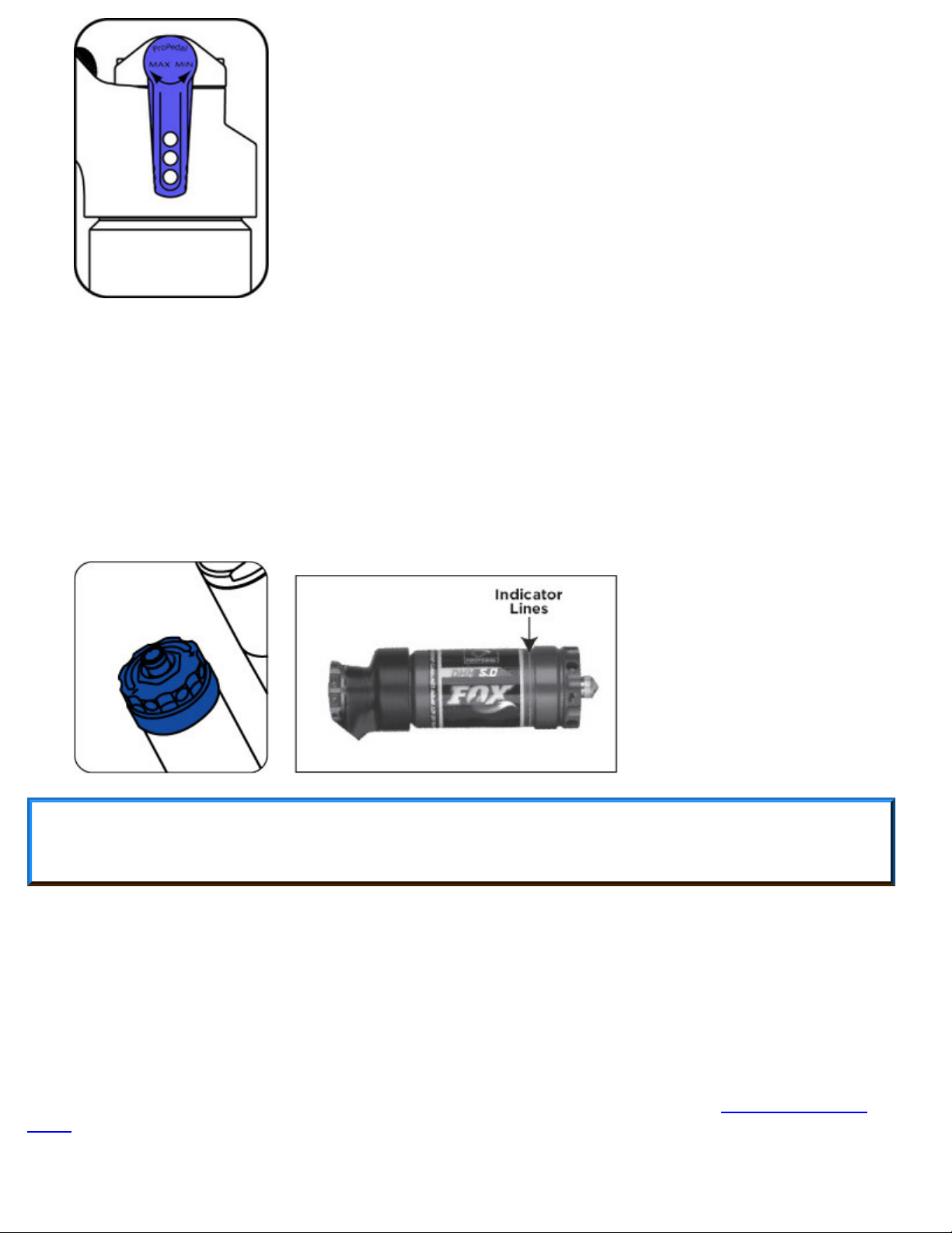
Adjusting Rebound
Rebound controls the rate at which your shock returns after it has been compressed. The proper rebound
setting is a personal preference, and changes with rider weight, riding style and conditions. A rule of thumb is
that rebound should be as fast as possible without kicking back and pushing the rider off the saddle.