FPM Agromehanika 627 926C Guide

FPM AGROMEHANIKA | 1
DISC MOWERS C
USER GUIDE AND LIST OF SPARE PARTS
PLEASE READ CAREFULLY BEFORE USE
FPM 627 926C
FPM 627 927C
FPM 627 928C
FPM 627 715C
FPM 627 113C

2
C O N T E N T S
1. INTRODUCTION
General information about the product
Technical characteristics
Identication plaque
Limited warranty
4
4
4
5
5
2. SAFETY WARNINGS
Meaning of the warning signals
Recommendations for safe use
General recommendations
Fitting the machine onto a tractor
Using the Cardan joint
Hydraulic installations
Maintenance
Special recommendations
Warning labels
6
6
6
7
7
7
7
7
8
8
5. USING THE MOWER
Before use
Working with the mower
Adjusting the cutter bar
Adjusting cutting height
Safety device
16
16
17
18
18
18
3. ASSEMBLY
Assembling the protective frame carrier
and hydraulic cylinder
Assembling the internal protective sheet
metal
Assembling the swath-former
Assembling the protective frame
10
10
11
11
12
4. FITTING THE MOWER
Fitting onto a tractor
Cardan joint
Transport
13
13
14
15
FOREWORD 4

FPM AGROMEHANIKA | 3
19
19
19
20
20
21
21
21
21
22
6. ADJUSTMENTS AND MAINTENANCE
Discs and cutting blades
Controlling the blades and cutting discs
V-belts
Oiling
Torque multiplier
Cutter bar
Oiling the grease ttings and sliding
surfaces
Oiling the Cardan joint
Schedule for regular servicing and
maintenance
7. FITTING THE MOWER
Parking
Storing
23
23
23
9. LIST OF SPARE PARTS
Compliance statement
25
46
8. USEFUL TIPS 24

4
FOREWORD
IMPORTANT!
This user guide contains detailed information required for the proper use and maintenance of the product.
We are asking you to read it carefully before using the product and to observe the instructions for proper functioning, main-
tenance, and safe use. The instructions will help you get to know all features and characteristics of the product, as well as the
sequence for performing all necessary operation during use.
Failure to observe the recommendations and instruction can lead to damage to the product and to serious injury to the user
and nearby persons.
NOTE: FPM AGROMEHANIKA IS CONSTANTLY STRIVING TO IMPROVE AND ENHANCE ITS PRODUCTS AND THEREFORE RESERVES THE RIGHT
TO CARRY OUT MODIFICATIONS AND IMPROVEMENTS WHEN NEEDED, WITH NO OBLIGATION TO MODIFY PREVIOUSLY MANUFACTURED OR
SOLD EQUIPMENT.
1. INTRODUCTION
1.1 General information about the product
Disc mowers KC are rear tractor mowers designed for harvesting all types of grasses, forage plants, and road-side surfaces, and for communal
works.
These mowers possess strong cutter bars with serrated transfer and are characterised by high reliability even during intensive use. They are
also suitable for use under dicult working conditions, such as: laid down or tangled grass, wet ground, ground with molehills, ground at an
incline, during moderate rains, or similar.
NOTE: THE NAMES OF MOWERS, PRODUCTS, AND MACHINES IN THIS MANUAL REFER TO DISC MOWERS.
1.2 Technical characteristics
Type FPM 627.926C FPM 627.927C FPM 627.928C FPM 627.715C FPM 627.113C
Working width (m) 1.6 2.0 2.4 2.8 3.15
Number of discs 4 5 6 7 8
Number of blades per disc 2 2
Linkage at three points at three points
Tractor category I, II I, II
Minimal tractor power -kw(hp) 21(29) 25(34) 31(42) 38(52) 41(56)
Number of tractor shaft revolutions(rpm) 540 540
Number of disc revolutions (rpm) 3030 3030
Maximum tractor working speed (km/h) 16 16
Maximum work output (ha/h) 2.5 3.2 3.8 4.5 5
Cut height (cm) 3-9 3-9
Swath width (m) 1.2 1.4 1.8 2.2 2.5
Cutter bar suspension system hydraulic hydraulic
Required hydraulic connector 1-way valve 1-way valve
Safety mechanism yes (oating lever) yes (oating lever)
Transport position width tractor width+25cm tractor width+25cm
Weight (kg) 366 405 452 530 650
CAUTION!THE MANUFACTURER IS NOT RESPONSIBLE FOR THE CONSEQUENCES OF
INCORRECT USE AND/OR DISREGARD OF RECOMMENDATIONS GIVEN IN THESE INSTRU-
CTIONS.

FPM AGROMEHANIKA | 5
1.3 Identication plaque
For the purposes of ordering spare parts, as well as for any questions concerning the proper use and maintenance of the product, it is necessary
to state information from the identication plaque. In order for this information to be always easily available to you, we advise you to enter it
into the blanks of the illustration below.
The identication plaque contains the following information:
- In the eld marked with “Z”– you will nd the number of certicate (document) for safety at work.
- In the eld marked with “MASA/WEIGHT” – you will nd the product’s weight;
- In the eld marked with “GODINA/YEAR” – year of manufacture (last two digits);
- In the eld marked with “SERIJA/TYPE” – product label;
- In the eld marked with “№”– you will nd the product’s serial number composed of nine digits;
NOTE: USING ORIGINAL SPARE PARTS APPROVED BY FPM AGROMEHANIKA GUARANTEES PROPER FUNCTIONING OF THE MACHINE, AS WELL
AS SATISFACTORY PERFORMANCE. USING SPARE PARTS AND EQUIPMENT NOT APPROVED BY FPM AGROMEHANIKA EXCLUDES ANY LIABILITY
OF THE MANUFACTURER FOR ANY POSSIBLE DAMAGE.
1.4 Limited warranty
I General conditions
The company FPM AGROMEHANIKA A.D. (hereafter FPM) guarantees that the product will function properly for 2 years from the date of the
product’s delivery to the buyer. This warranty covers all parts manufactured by FPM, whose lifetime is longer than two years and which have
been determined to be faulty due to material defects, bad manufacturing, and/or incorrect assembly, by the assessment of FPM or its authorised
service centre.
For buyers in Serbia, FPM provides all rights pursuant to Articles 54 and 55 of the Law on Consumer Protection, and for buyers outside of Serbia,
the rights that are in accordance to that country’s relevant laws shall apply.
II Responsibilities of FPM according to the warranty
FPM has committed itself to replace and repair any defective parts/assemblies during the warranty period free of charge, if that has been caused
by material defects, bad manufacturing, or incorrect assembly. The deadline for removing the fault is up to 45 days from the day of reporting.
The replaced parts are the property of FPM and they are handed over to the authorised serviceperson or distributor.
III Exceptions and limitations
This warranty does not cover:
- parts made of wood;
- parts/assemblies not manufactured by FPM (tyres, plastics, belts, engines, etc.). These items are covered by the warranty of the responsible
manufacturer:
- parts that are normally expended during the product’s use (consumables), as well as lubricants. These parts are specically listed/labelled in
the user manual for each product;
- regular servicing and maintenance of the product as specied by the user guide.
The warranty does not cover a fault resulting from:
- an act of a higher power (ood, thunder, earthquake, etc.);
- not respecting and observing the instructions set out in the user guide, and relating to proper use, setting, maintenance, servicing, and
storing of the product;
- changes and modications to the product that are not stipulated by FPM;
- installation of non-original parts, or parts and lubricants that are not approved or recommended by FPM;
- the user’s failure to immediately report a fault or the user’s opposition to an immediate repair;
- unprofessional servicing by the user or an unauthorised service centre.
All expenses of transporting the product or parts to an authorised service centre and back, as well as oil changes are borne by the user.

6
IV Responsibilities and liabilities of the user
The user is obliged to respect all instructions stated in the user guide, and relating to proper use, setting, maintenance, servicing, and stor-
ing of the product, as well as to carry out all actions intended for regular maintenance and servicing of the product at an authorised service
centre. In case of a problem occurring during use, they must immediately contact a distributor from which they purchased it or a nearby au-
thorised service centre. Also, the user must give for inspection a receipt and a warranty form to the distributor or an authorised service centre
in order to take advantage of warranty rights.
V Procedure for resolving complaints
The buyer and the distributor (seller) have a responsibility to ll in the warranty card correctly and send one copy to the address of FPM. This
form must be sent within 7 days from the date of purchase in order to conrm the warranty and ensure post-sale support.
The product’s fault must be reported within the warranty period to the distributor from whom the product was bought or at a nearby au-
thorised service centre within 30 days at most from the day when the problem occurred. In order to have rights under warranty, the user is
obliged to hand over the receipt and warranty card for inspection when delivering the defective product to an authorised service centre or
upon an authorised serviceperson’s visit.
2. SAFETY WARNINGS
Safety warnings of a potential danger are indicated in two ways:
1. Recommendations for safe use in the manual;
2. Warning signed (labels) on the product.
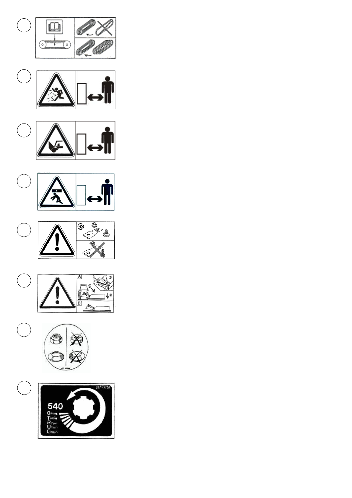
2.1 Meaning of the warning signals
Symbols and warnings in this manual describe potential danger during use, inspection, or maintenance of the product and are divided into 4
groups according to the level of the potential danger. These warnings are intended to draw the user’s attention to be cautious for their own
safety and for that of people who are working with them. Failure to respect the instructions and warnings described may result in serious
injuries or, in the worst case, death.
DANGER! CAUTION!
WARNING!
2.2 Recommendations for safe use
2.2.1 General recommendations
1. The stated instructions for use, maintenance, and safety at work must be respected unconditionally in order to ensure safe and reliable
functioning.
2. Before starting work, the operator must be fully familiar with the functioning of all parts of the machine, and especially know how to
quickly and safely turn o the machine in case of danger.
3. Use a tractor with a cabin. Keep all windows closed during work.
4. Before starting the machine and during use, pay attention that other persons or animals are at a safe distance.
5. Never take other persons on the machine during work or transport.
6. While attaching or detaching the machine from a tractor, always move the leaning switch to the appropriate position.
7. Be especially careful while attaching or detaching the machine from a tractor.
8. Before use, check that the front tractor shaft is suciently weighted. Attach weights to the appropriate place if needed.
9. Pay attention not to exceed the permitted shaft load and total tractor weight, as specied by the tractor manufacturer.
10. Respect the prescribed and permitted dimension during transport.
11. Before beginning transport on public roads, be sure to insure the machine for a safe drive, label it appropriately, and respect public
trac rules.
12. Before transporting the machine on public roads, be sure to set it into the transport position as explained in this manual.
13. Never turn on the joining axle of the tractor while the machine is in the transport position.
14. Never leave the driver’s seat while the machine is operating.
15. Adjust the speed of motion to working conditions and conditions on the road. Always avoid sudden changes of direction.
16. Be especially careful while turning and keep the machine’s dimensions in mind.
17. Remove all foreign objects from the working area (the eld), which can damage the machine and endanger your safety.
18. Before you leave the tractor or before making adjustment, repairs, or maintenance of the machine, put the machine on the ground,
turn o the Cardan joint power, turn o the tractor engine, take out the key, and pull the tractor parking brake.
19. Do not stand between the machine and the tractor unless the tractor parking brake has been pulled and/or wedges are placed under
the wheels.
20. Before making any adjustments, repairs, or maintenance of the machine, make sure the machine does not accidentally move.
NOTE
Indicates a high-risk situation which, if not
avoided, could lead to serious injuries or
death.
Indicates a potentially dangerous situation
which, if not avoided, could lead to serious
injuries or death, as well as material damage.
Indicates a potentially dangerous situation
which, if not avoided, could lead to material
damage and minor injuries.
Indicates general indications and tips for safe,
proper, and ecient use of the product.

FPM AGROMEHANIKA | 7
2.2.2 Fitting the machine onto a tractor
1. Before every attaching or detaching of the machine from a tractor, block hydraulic controls in order to prevent any unwanted rising or
lowering.
2. While attaching the machine onto a tractor, make sure that the tractor linkage points correspond to the machine linkage points.
3. The area around the linkage points is very dangerous, so be particularly careful.
4. While using external hydraulic controls, do not stand between the tractor and the machine.
5. Block lateral motion of joining levers of the tractor during transport.
6. While transporting the machine, x the hydraulic controls of the tractor in the appropriate position.
7. Do not work with or transport the machine on uneven or sloping ground with a narrow wheel tractor.
2.2.3 Using the Cardan joint
1. Only use the Cardan joint bundled with the machine or one prescribed by the machine’s manufacturer.
2. Protective parts of the Cardan joint must be installed and in good condition.
3. Pay attention to the required crossing of the pipes in the transport and working positions.
4. You may only attach or remove the Cardan joint if the tractor output shaft is turned o,
the engine is turned o, and the ignition keys taken out.
5. If the Cardan joint has a safety link, place the link towards the machine while attaching the Cardan joint.
6. Always take care to attach the Cardan joint properly.
7. Fasten the protective parts of the Cardan joint with anti-rotation chains.
8. Before turning on the tractor output shaft, make sure that the selected number and direction of rotations is compatible with manufac-
turer recommendations.
9. Before turning on the tractor output shaft, make sure that all persons or animals are at a safe distance.
10. Do not turn on the tractor output shaft until the tractor engine has been turned o.
11. Make sure that the working angle is compatible with manufacturer recommendations.
12. Once you have detached the machine, place the Cardan joint in the appropriate casing.
13. Once you have detached the Cardan joint from the tractor, place the safety lid onto the tractor output shaft.
14. If the Cardan joint gets damaged, immediately replace it with a new one or contact a nearby service centre. Any unprofessional in-
tervention may lead to unbalancing of the Cardan, which can lead to improper functioning and damage to the machine or the tractor
output shaft.
2.2.4 Hydraulic installations
1. WARNING! The hydraulic installation of the machine is under great pressure (maximum working pressure is 200 bars).
2. While attaching the hydraulic cylinder tube, pay attention that the connectors t appropriately.
3. While attaching the hydraulic tube link to the tractor hydraulic valve, be careful that the hydraulic installation is without pressure either
towards the tractor or the machine.
4. We recommend that you mark the hydraulic connectors in order to avoid erroneous connections. Mixing opposite-function connectors
(for raising and lowering) may cause risk of injury.
5. Regularly check hydraulic tubes and be sure to replace them after 5 years of use, at most. Immediately replace damaged or prematurely
worn tubes. The replaced tubes must correspond to the technical requirements of the machine’s manufacturer.
6. If you notice leaking from the hydraulic system, take all necessary measures to prevent an accident.
7. Hydraulic uid squirting under high pressure may puncture the skin and cause injury. In case of injury, immediately seek medical atten-
tion! There is risk of infection!
8. Before working on the hydraulic installation, place the machine on the ground, release pressure from the hydraulic installation, and
turn o the tractor engine.
2.2.5 Maintenance
1. Before checking for any faults with the machine or making adjustment, repairs, or maintenance of the machine, turn o the Cardan joint
power, turn o the tractor engine, take out the key, and pull the tractor parking brake.
2. Regularly check that nuts and bolts are screwed up properly. Tighten them if needed.
3. In case that the machine is raised, secure and fasten it using appropriate support before performing any action on it.
4. When replacing working parts, always wear protective gloves and use appropriate tools.
5. Regularly check protective parts intended for the safe use of the machine. Replace them immediately if needed.
6. Spare parts must comply with manufacturer recommendations and standards. Only use original FPM Agromehanika spare parts.
7. Repairs of parts that are under pressure or weighed down (hydraulic cylinders, tubes, springs, etc.) may only be carried out by trained
sta with the appropriate equipment for such works.
2.2.6 Special recommendations
1. Keep a safe distance from the mower when the discs are revolving.
2. Do not wear too loose-tting clothing in order to prevent them from being caught by the mower’s moving parts.
3. Before using the mower, place all protective parts into the appropriate position.
4. Before each use of the mower, check that all the parts (nuts, bolts, and others) are suciently screwed in.
5. It is especially important that the cutting elements are properly tted for safe use. Only use parts and tools recommended by the manufacturer.

8
6. Before each use of the mower, check the condition of the cutting elements (blades, discs). In case they are damaged or overly-worn,
replace them immediately.
7. When replacing worn-out or damaged blades, always replace them in pairs in order to avoid unbalancing the discs.
8. Regularly check the mower’s protective canvas and other protective parts. Immediately replace the worn-out or damaged canvas and
parts with new ones.
9. When the Cardan joint power take-o is turned o, the mower’s moving parts will continue to rotate for some time. Wait for the moving
parts to come to a halt before approaching the machine.
10. Remove all foreign objects from the working area (the eld), which can damage the machine and endanger your safety.
11. Never use the machine when driving in reverse.
12. If a collision with an obstacle occurs, immediately stop the tractor, turn o the Cardan joint power, turn o the tractor engine, take
out the ignition key, and wait for the moving parts to come to a halt. Check the state of the entire machine before continuing with work.
13. We recommend that an authorised service representative checks the state of your machine after each season and especially the cut-
ting elements.
2.3 Warning labels
Labels with warnings are put on the machine for your safety, as well as the safety of people who are working with you. The labels must be
clearly visible and legible, otherwise replace them with new ones.
NOTE: EVERY LABEL HAS ITS CATALOGUE NUMBER AND CAN BE ORDERED DIRECTLY FROM THE MANUFACTURER OR AUTHORISED DEALER.
NO OBLIGATION TO MODIFY PREVIOUSLY MANUFACTURED OR SOLD EQUIPMENT.
Indicates a potentially dangerous situa-
tion which, if not avoided, could lead to
material damage and minor injuries.
1 2 Before making adjustments, oiling, or clean-
ing the machine, turn o the tractor, take
out the key, and wait for the moving parts to
come to a halt.

FPM AGROMEHANIKA | 9
4
5
6
7
8
9
10
3For your mower to function properly, the V-belts must be
properly tted, so that the deection is 10mm.
When replacing worn-out belts, replace the entire set of belts,
regardless of the condition of one belt compared to others.
Rotating elements! During the machine’s operation, there is a
possibility of objects being thrown from the ground at a great
distance. Keep a safe distance from the machine.
Rotating elements! Keep a safe distance from the machine’s
moving parts while the tractor is in operation, and the Cardan
joint is turned on.
Danger of objects falling. Keep a safe distance from the ma-
chine.
Only use original parts and those recommended by FPM
Agromehanika.
Before detaching the mower from the tractor, do the following:
1. Lower the cutter bar into a horizontal position.
2. Put the axle in the parking position.
3. Lower the machine to the ground.
The machine must always be parked with the cutter bar in the
horizontal position (B).
Be sure to use the appropriate original parts.
Number of revolutions of the Cardan joint must not exceed
540 rpm.

10
For mowers FPM 627.928/715113, fasten the end of the protective
frame carried (D) with bolt A (M16x50) to the swath former carrier (S).
Tightening torque 28 daNm. Then fasten bolt H (M12x30) gure 12.
Now tighten the bolt (E), 4 commands (gure 11), and the required
torque for tightening is 14 daNm.
Fasten the hydro-cylinder fork (A) as shown (gure 14), and secure
the axle (N) with elastic pins (F) (ø 5x30).
Fasten the carrier frame (D) (gure 11) to the four-screw multiplier
(M12x35) (E) as shown in gure 11 (tighten the screws with the torque
of 14 daNm).
NOTE: FOR MOWERS FPM 627.928/715/113, DO NOT TIGHTEN
THESE FOUR SCREWS FULLY “FOR NOW”.
For mowers FPM 627.928/715/113, fasten the external metal casing
with four screws (I) (M10x25) and 4 self-locking nuts (M10) onto the
protective frame carrier as shown (gure 13).
3. ASSEMBLY
Safety warnings of a potential danger are indicated in two ways:
In order to facilitate the transport of the mower, certain parts and assemblies are disassembled. Depending on the target market, the extent
of disassembling may vary.
In order to assemble the mower properly and prepare it for use, do the following:
3.1 Assembling the protective frame carrier and hydraulic cylinder

FPM AGROMEHANIKA | 11
3.2 Assembling the internal protective sheet metal
3.3 Assembling the swath-former
- Fasten the internal protective sheet metal (J) with four screws (H)
(M10x20), four at washers (dimensions 10x21x2) and four self-lock-
ing nuts (M10), as shown in gure 15.
- The swath-former is tted by fastening the swath-former carrier
onto the spot (O) using a screw (M12x80), coil spring, special washer,
and self-locking nut (gure 16). Pay attention that the nut ts in such
a way that the swath-former remains mobile. Fasten the wooden le-
ver (R) to the sheet metal (U) using the connective panel (Y), screw
(W)(M8x50), and two self-locking nuts (M8)(gure 16).

12
3.4 Assembling the protective frame
- Fasten the front half of the protective frame (C) with screws (F)
(M10x25) to the appropriate holders (B), using plastic washers (Q)
(ø10) and nuts (O) (M10) (gure 17).
- Fasten the folded front half of the protective frame to openings (N)
using bolts (M10x75) and secure it with self-locking nuts (M10). Tight-
en the nuts in such a way that the protective frame can rotate freely
(see gure 17 and 18).
- Then fasten the rear half of the protective frame (W) with screws
(F)(M10x25) to the appropriate holders (A), using plastic washers (Q)
(ø10) and nuts (O) (M10) (gure 18).
- Tie the protective awning (D)(gure 19) to the frame using belts at
places marked with E.
Place the belt with a loop on the inside in the rear part at point A, and
the belt with holes in the front movable part at the bottom on the
inside at point B (gure 19).

FPM AGROMEHANIKA | 13
4. FITTING THE MOWER
4.1 Fitting onto a tractor
- For the mower to function properly and optimally, the edge of
the cutter bar must be at least 5 cm away from the external edge of
the wheel tract. Figures 32, 33, and 34 show examples of tting the
mower onto three dierent types of tractors – for tractors that have
a wheel gap of 1.32m, connect the tractor levers as shown (gure 32).
For a wheel gap of 1.5 m attach the tractor levers according to gure
33. For tractors with a wheel gap of 1.65 m place the tractor levers as
shown in gure 34.
NOTE: ADJUST THE MOWER SO THAT THE GAP A IS AROUND 5
CM. CHECK THAT THE TENSION CHAIN (C) ALLOWS THE CUTTER
BAR TO TAKE THE APPROPRIATE POSITION FOR OPERATION.
- Make sure to properly tie the awning to the frame while assem-
bling! The awning (D) is tied to a plastic washer (Q), over which a nut
(O) and screw (F) is tied (gure 20). This image shows how to place
the belt with holes (A) and the belt with a loop (B).
- Mount the carrier (J) at the end of the protective frame, fasten it
with two screws (R) (M10x30), two washers (T)(ø 10) and two self-lock-
ing nuts (O) (M10) (gure 17).
- Fasten the additional carrier (S) with a screw (V) (M10x50), and a
screw (R) (M10x45) to the protective frame (see gure 21 and 17).
- Figure 21A shows how to roll the awning into the transport posi-
tion. After rolling the awning, fasten its front and rear part using belts
(A and B) as shown in gure 19, and the mower is ready for transport.
DANGER! WHEN WORKING WITH THE MOWER, THE
PROTECTIVE CANVAS MUST ALWAYS BE PLACED ONTO
THE FRAME AND LOWERED INTO THE WORKING POSI-
TION.

14
Fitting is achieved in the following way:
.
1 – Move the tractor backwards, using
hydraulics bring down the lower tractor levers
to the height of the mower linkage point axis
and carry out the tting and
locking of levers as shown under
A in gure 35.
2 – Upper tractor lever – connect
the coupling (B) with the axle (C)
to the connector on the upper part
of the carrier frame, depending on the
category of tractor turn the thinner or
thicker part of the axle and secure it with
existing tighteners.
3 – Connect the hydraulic tube connector to the appropriate
hydraulic connector on the tractor (one way)
4 – Following that action, using hydraulics
raise the mower o the ground to the
required height for transport.
5 – For safe transport of the mower,
pull out the tightener (A) (gure 36) and
lock the parking switch (B) into the groove (C)
and the mower is ready for transport.
4.2 Cardan joint
It is very important for the Cardan joint to be properly set while con-
necting it to a tractor. Cardan cranks must never be allowed to get
stuck together when the machine is raised into the highest or low-
ered into the lowest position. The Cardan joint has a safety link. Make
sure to place the safety link towards the mower, so that the cutter
can be turned on.
If you determine that the Cardan joint is too long and cannot be con-
nected to the tractor, it is necessary to shorten it. The following im-
ages illustrate the procedure for shortening the Cardan joint.
1 – Join rst one, then the other half of the Cardan joint onto the
tractor and the machine, keep one half next to the other, and by
various adjustments of the tractor and the machine, adjust the
length of 10 mm and label it on the protector, (gure 25).
2 – Cut o the protective plastic, see gure 26.
3 – Cut o the prole tube, see gure 27. Further modications to
the plastic and tube are not permitted.
CAUTION! THE FOLLOWING ACTIONS AND INSTRUCTIONS MUST BE RESPECTED IN ORDER TO AVOID DAMAGE TO
THE MACHINE AND CARDAN JOINT OR PREMATURE WEARING OF THE CARDAN JOINT. NEVER ATTACH THE CARDAN
JOINT TO THE TRACTOR OUTPUT SHAFT WITH 750 OR 1000 RPM.

FPM AGROMEHANIKA | 15
4 – Lower the sharp outer edges (gure 28).
5 – Clean and oil (gure 29). Connect the Cardan joint tubes with
one another.
6 – The Cardan joint protection must never be removed, nor
moved during operation.
Attach the protection carrier chain onto the machine shaft pro-
tection (gure 30).
7 – The Cardan joint must never operate under too big an angle
(10° at most)° (gure 31).
4.3 Transporting the mower
Before transporting the mower on public roads and from one work-
ing area to another, do the following:
1. Turn o the tractor output shaft and wait for all moving parts
to come to a halt.
2. Raise the mower using hydraulics to the required height for
transport, press the peg (A) (gure 36A) and raise the parking
switch (B) so that the groove (C) reaches the height of the peg
(gure 36A).
3. Move the axle (A) (gure 37), on the oating lever into the bear-
ing for the transport position (see drawing of label B), secure it
with a tightener, whereby you prevent the lever from oating.
DANGER! IN ORDER TO ENSURE SAFE FUNCTIONING OF THE CARDAN JOINT, PLACE ALL SAFETY PROTECTIONS AT
THE APPROPRIATE PLACES AND SECURE THEM APPROPRIATELY. IF THE PROTECTIONS ARE DAMAGED OR WORN-
OUT, REPLACE THEM IMMEDIATELY.

16
4. Fold the front half of the protective canvas (A)
backwards (see the arrow) (gure 38), and
tie it with the appropriate belts.
5. Lift the cutter bar using the hydraulic cylinderinto the trans-
port – vertical position.
6. Move the lever (T) from the neutral position, i.e. connect it us-
ing the carrier frame and secure it using the tightener (L) (gure
39), and the mower is ready for transport.
5. USING THE MOWER
5.1. Before first use
Before starting the mower for the rst time, perform the following
checks:
No. Description All right (√)
1Product integrity
2Check that the V-belts are tightened
3Check that the pulley nuts are tightened
4Check that all screws are tightened
5Check the position of discs and cutting blades
6Check that the cutting discs are tightened
7Check the level of oil in the multiplier
8Check the level of oil in the cutter bar
9Check that all grease ttings are oiled
5.2 Working with the mower
Once you have lowered the cutter bar from the transport into the work-
ing position, turn on the input shaft and let the cutter bar revolve for
some time at a low number of revolutions in order for the oil to spread
throughout the cutter bar casing.
Before you start mowing, increase the number of shaft revolutions to
540 min-1.
It is very important that the mower operates at a prescribed number of
output shaft revolutions, otherwise the results of mowing will be unsat-
isfactory, and at certain times congestions may occur.
The speed of motion should be adapted to ground conditions.
The mowing itself can be performed continually, i.e. without breaks
and raising the mower o the ground while turning, because there is
no congestion when the mower reaches a mowed mass, and due to the
specic shape of the cutting discs the already mowed mass will not be
ground.
Take measures of extreme caution when working on uneven ground.
Adjust the mower in such a way that the possibility of the blades hit-
ting foreign objects or the ground is minimal.
1. Tilt the cutter bar at an angle using the handle on the coupling
(B) (gure 43) which adjusts the cutting height.
3. Check that the cutting blades rotate when the cutter edge hits
an obstacle.
4. Sharpen the blades (using the appropriate tools).
The protective canvas (awning) holds back foreign objects that get
deected o the blades and cutting discs, and protects the user and
other persons present.
WARNING! THE FOLLOWING ACTIONS AND IN-
STRUCTIONS MUST BE RESPECTED IN ORDER TO
AVOID DAMAGE TO THE MACHINE AND CARDAN
JOINT OR PREMATURE WEARING OF THE CARDAN
JOINT. NEVER ATTACH THE CARDAN JOINT TO THE
TRACTOR OUTPUT SHAFT WITH 750 OR 1000 RPM.
WARNING! BEFORE STARTING WITH WORK, RE-
MOVE STONES, FOREIGN OBJECTS, AND HIDDEN
OBSTACLES FROM THE WORKING AREA.
DANGER! WHEN WORKING WITH THE MOWER, THE
PROTECTIVE CANVAS MUST ALWAYS BE PLACED ONTO
THE FRAME AND LOWERED INTO THE WORKING POSI-
TION.
DANGER! BEFORE STARTING WORK, MAKE SURE THAT OTHER
PERSONS OR ANIMALS AND NOT WITHIN THE MOWER’S WORK AREA.

FPM AGROMEHANIKA | 17
5.2.1 Adjusting the cutter bar
1. Place the axle (A) (gure 40) into the working position. This re-
leases the spring and allows the cutter bar to properly handle
the ground.
NOTE: FOR SWITCHING THE AXLE INTO THE WORKING POSITION,
THE CUTTER BAR MUST BE RAISED IN THE TRANSPORT POSITION.
2. Remove the transport position level (T) from the mower frame
carrier and attach it onto the frame (awning carrier) and fasten it
with the existing elastic tightener (L) (gure 41).
3. Using the hydraulic cylinder, lower the cutter bar into the
working position.
4. Adjust the mower using tractor levers so that the linkage point
centres (A) are at the height of 450 mm (gure 42).
5. Insert the chain (D) into the opening on the tension hook (A)
on the tractor as shown in gure 43. Completely lower the tractor
levers, which adjusts the height.
The adjusting is good if:
- The cutter bar is leaning on the ground
- The chain is bound and tightened
- The distance between the linkage points and the ground is
around 400 mm.
Managing the hydraulic cylinder is of great importance for the prop-
er functioning of the mower.
The managing is carried out during work, which will facilitate your
work and increase working output.
WARNING! BE VERY CAREFUL WHEN LOWERING
THE CUTTER BAR! THERE MUST NOT BE ANYONE IN
THE WAY WHILE LOWERING THE MOWER’S CUTTER
BAR.

18
5.2.2 Adjusting the cutting height
The cutting height is adjusted by rotating the entire cutter bar around
the longitudinal axis. This is achieved by shortening or lengthening
the coupling length (B) (gures 43 and 44). This adjustment should
be carried out very carefully in order to achieve a proper cut while
mowing (gure 44).
5.2.3 Safety device
The safety device is by default properly set for working under nor-
mal working conditions, and is activated only when the cutter bar
encounters hidden (hard) obstacles in the ground. For mowers with
four discs, the spring (B) is set to the measurement (A) which equals
102 mm (gure 45).
For mowers with ve, six, seven, or eight discs, the safety system is
congured using plate springs to the length of 94 mm, shown as Y
on gure 46.
If there is a need to exceptionally modify the safety device for the
user in order to adapt it to local conditions, the main principle is that
the safety device spring must be adjusted in such a way as not to be
activated under normal working conditions.
NOTE: CHECK THAT THE SAFETY DEVICE CASING IS OILED. IF NOT,
OIL ALL SLIDING PARTS WITH TECHNICAL OIL.
If the cutter bar hits a hidden obstacle while in operation, the safety
device (R) is activated which detaches the cutter bar (gure 45).
Then take the tractor a little in reverse and lift the mower using the
tractor levers. Swing the cutter bar towards the tractor, which will
restore the safety system to the original, working position.
5.2 Swath-former
For proper setting of swath shape and mowed mass ow, it is neces-
sary to loosen or tighten the coil spring (A) (gure 53). In case of more
dicult working conditions, the swath-former angle must be greater
in relation to the cutter bar (as close to 90° as possible).
CAUTION! IT IS VERY IMPORTANT TO ADJUST
THE CUTTER BAR WHILE ADJUSTING THE CUTTING
HEIGHT SO THAT THE BLADES DO NOT HIT THE
GROUND DURING OPERATION. OTHERWISE, THE
BLADES WILL QUICKLY GET DAMAGED, AS WILL
THE ROOTS OF PLANTS. PAY SPECIAL ATTENTION
IF YOU ARE WORKING ON UNEVEN GROUND.
CAUTION! NEVER TIGHTEN THE SPRING TOO
MUCH IN ORDER FOR THE SAFETY DEVICE TO
WORK PROPERLY.
CAUTION! WHEN THE SAFETY DEVICE ACTI-
VATES, IMMEDIATELY STOP THE TRACTOR AND
TURN OFF THE OUTPUT SHAFT.

FPM AGROMEHANIKA | 19
6. ADJUSTMENTS AND MAINTNANCE
For tightening the cutting discs, it is necessary to tighten the screw
(Q) (gure 51) with a torque of 18 daNm.
When mounting the cutting discs under the nut (Q), use a spring
washer (R) for properly fastening the discs. It is always necessary to
install a protective washer (P) beneath the bearing, which prevents
dust and dirt from entering the cutting disc casing (gure 51).
6.1.1 Controlling the blades and cutting
discs
A) BLADES: They should be checked minutely before starting with
mowing. Quality cutting and good, safe work depend on well-sharp-
ened blades.
1. DAMAGED BLADES
Very rough, rugged, and damaged blade edges lead to:
- increased risk of accident;
- lower quality cutting;
- risk of damage to the cutter bar.
2. WORN-OUT BLADES
The width (B) of a worn-out blade, measured from the distance of
10 mm from the cutting disc edge must not be less than 3/4 of the
normal blade width.
The length of the oval opening (L) on the cutting blade must not
exceed 18 mm.
6.1 Discs and cutting blades
The discs, cutting blades, and blade carriers are of a very quality
build. The blades and blade carriers are made of a special steel alloy,
which is hardy and resistant to wearing, and therefore gives them a
long working life.
NOTE: ONLY USE ORIGINAL PARTS AND THOSE RECOMMENDED BY
FPM AGROMEHANIKA.
After long use, the blades’ cutting edges start to get blunt, so that
the cutting quality will no longer be satisfactory. The blunted edges
of the cutting blades require increased power, while the stocks of the
mowed plants are uneven and rugged.
Before replacing the blades, clean the earth and dirt o the blade
carrier and nut, as shown under A in gure 50. Unscrew the nut and
remove the blade carrier from its bearing.
Two cutting blades are mounted onto each cutting disc, which
revolves clockwise, while the neighbouring disc revolves count-
er-clockwise.
When you have ascertained that the cutting blade edges have been
blunted, replace the blades on the neighbouring discs together,
since the blades have two edges.
It is possible to sharpen the cutting blade edges as long as the tem-
pered edge (thermally reinforced) remains, however it is necessary
to preserve the cutting edge angle. If the damage is great, the blade
must be replaced with a new one.
All discs should be adjusted in such a way that the blade axes take a
right angle (see gure 50).
For tightening the screw (A) (gure 50) which holds the cutting
blades, use a torque of 7.5 daNm.
DANGER! BEFORE MAKING ANY ADJUSTMENTS, RE-
PAIRS, OR MAINTENANCE OF THE MOWER, SWITCH OFF
THE CARDAN JOINT POWER, TURN OFF THE TRACTOR,
TAKE OUT THE KEY, AND WAIT FOR THE REVOLVING
PARTS TO COME TO A HALT.
WARNING! BEFORE DOING MAINTENANCE AND RE-
PAIRS TO THE MOWER REMOVE ALL FOREIGN OBJECTS
AND PARTS SINCE THEY CAN BE THROWN AT NEARBY
PERSONS.

20
B) CUTTING DISCS): They should be checked regularly! (Especially
check the screw tightening torque.) The tightening torque equals 7.5
daNm.
- Perform a check immediately after hitting a hidden obstacle.
- Perform a check when replacing the blades.
Always mount two blades of the same type onto a cutting disc, in
order to avoid unbalancing the disc.
Perform a check prior to every mowing season.
1. You must replace the blade carrier in the following cases:
- When there are visible deformities.
- When the head gets worn at the blade contact area.
- When the nominal circumference of the blade carrier
Dn = 16 mm reaches a maximum value on the worn blade
carrier of D = 13 mm.
2. You must replace the nut in the following cases:
- When the contact protective mass in the nut loses elasticity,
which is characterised by frequent loosening.
- When the wearing of the nut reaches a value of a = H/2.
6.2 V-belts
The V-belts must be properly tightened in order to prevent excessive
slipping. Insuciently tightened belts cause the cutter bar to oper-
ate badly and to damage and tear prematurely.
In order to tighten the belt, loosen the nuts (A) (gure 52). Tighten
the nut (B) until the force of 9 daN is achieved, i.e. the deection of 10
mm between the belts. While doing that, make sure that the casing
ts the frame properly. Finally, tighten the nuts (A).
NOTE: CHECK THAT THE BELTS ARE STILL TIGHT AFTER THE FIRST
1/2 HOUR OF USE. WHEN REPLACING THE WORN-OUT BELTS, RE-
PLACE THE ENTIRE SET OF BELTS, REGARDLESS OF THE CONDITION
OF ONE BELT COMPARED TO OTHERS
6.3. Oiling
It very important to properly oil the transmission components in
order to full the strict requirement for working even in the most
dicult conditions. It is best to release the oil immediately after n-
ishing with work, since the oil is still warm then, and the residue has
still not settled.
NOTE: THE LISTED TIMES FOR OILING ONLY REFER TO NORMAL
WORKING CONDITIONS. IF YOU ARE WORKING IN MORE DIFFICULT
CONDITIONS, MORE FREQUENT OILING IS NEEDED.
CAUTION! USE OIL OF THE REQUIRED QUALITY
IN ORDER TO AVOID DAMAGE TO THE MACHINE. BY
PROPER AND REGULAR OILING YOU WILL ENSURE UN-
IMPEDED AND SAFE OPERATION.
CAUTION! THE OIL IN THE TORQUE MULTIPLIER
AND CUTTER BAR MUST NECESSARILY BE CHANGED
AFTER THE FIRST 8 HOURS OF OPERATION. ONLY USE
SAE 80 W EP OIL.
This manual suits for next models
4
Table of contents
Other FPM Agromehanika Farm Equipment manuals
Popular Farm Equipment manuals by other brands

Duratech
Duratech HAYBUSTER 107 DRILL Operating Instructions and Parts Reference

aivituvin
aivituvin AIR42 instruction manual

Redexim
Redexim Verti-Groom 2000 User manual and parts book

Raven
Raven SmarTrax installation manual

360 Yield
360 Yield 360 Y-DROP JOHN DEERE 4720 instruction manual

AGCO
AGCO Gleaner S67 Operator's manual