Roxell Minimax Line User manual

MINIMAX LINE - TABLE OF CONTENTS ROXELL - 001 - 2112
TABLE OF CONTENTS
CONTENTS
GENERAL INFORMATION
PART I : INSTRUCTIONS FOR THE USER
GENERAL SAFETY RULES I--3........................................................
DIRECTIONS FOR OPERATING THE SYSTEM I--4.......................................
-- PUTTING THE SYSTEM INTO USE -- CONTROL IUNIT -- FILLING THE HOPPERS --
-- USING THE SYSTEM WITH ONE DAY OLD CHICKS I--4...........................................
-- USING THE SYSTEM FOR OLDER B IRS -- AT THE END OF A CROP -- MAINTENANCE I--5.............
-- WHAT TO DO BEFORE INSTALLING THE NEXT BATCH OF BIRDS ? I--5.............................
-- PROGRAMMED FEEDING / ADVANTAGES / HOW TO PROGRAMME I--6............................
MAINTENANCE INSTRUCTIONS I--7..................................................
TROUBLE SHOOTING GUIDE I--8/9.....................................................
OPERATORS GUIDE I--10/11..............................................................
DECLARATION OF INCORPORATION OF PARTLY COMPLETED MACHINERY
EC--DECLARATION OF CONFORMITY
PART II : COMPONENTS
GENERAL LAY--OUT -- COMPONENT NUMBERS -- II--2/3..................................
OPTION : AUGER INJECTOR KIT II--4..................................................
PARTS MINIMAX LINE FEEDER PANS II--5..............................................
FEEDER LINE COMPONENTS II--6.....................................................
OPTION FOR DUCKS : FEEDER LINE COMPONENTS -- ST. ST. II--6.........................
STRAINER FOR 100KG HOPPER II--6...................................................
HOPPER EXTENSION II--7............................................................
100KG HOPPER II--7..................................................................
OPTION FOR DUCKS : 100 KGHOPPER-STAINLESS STEEL II--8............................
HALF COVER FOR 100KG HOPPER II--8................................................
CAST IRON BALL (OPTION) II--9......................................................
THUMPER (OPTION) II--9.............................................................
FEED INTAKE BOOT II--9.............................................................
TUBE II--9..........................................................................
OPTION FOR DUCKS : FEED INTAKE BOOT POULTRY ST. ST. II--10.........................
POULTRY INTAKE BOOT WITH SENSOR (OPTION) II--11..................................
OPTION : DOUBLE FEED INTAKE BOOT II--12............................................
DOUBLE POULTRY INTAKE BOOT W/SENSOR (OPTION) II--13.............................
INTERMEDIATE CONTROL II--14.......................................................
CONTROL UNIT: II--15.................................................................
OPTION FOR DUCKS : CONTROL UNIT STAINLESS STEEL II--16/17...........................
POWER UNIT II--18...................................................................
SUSPENSION COMPONENTS II--19......................................................
SINGLE EYE PULLEY II--20............................................................
HEAVY DUTY PULLEY II--20...........................................................
OPTION FOR DUCKS : HEAVY DUTY PULLEY--STAINLESS STEEL II--21.....................
HAND OPERATED CENTRAL WINCH II--22..............................................
MOUNTING PLATE F/HAND OPERATED CENTRAL WINCH II--22...........................
TELESCOPICAL WINCH DRIVE TUBE II--22..............................................
MOTOR II--22........................................................................
STANDARD : CONTROL SWITCH FOR WINCH II--22......................................

ROXELL - 001 - 2112 MINIMAX LINE - TABLE OF CONTENTS
OPTION : CENTRAL WINCH W/GEARBOX -- MOTOR OPERATED II--23......................
OPTION : CONTROL PANEL FOR CENTRAL WINCH II--24.................................
OPTION : CONTROL PANEL FOR CENTRAL WINCH II--25.................................
CUT--OFF SWITCH II--26..............................................................
CONTROL PANEL WITH TIME CLOCK II--27.............................................
BOX W/COUNTER II--27...............................................................
MINIMUM SWITCH II--28..............................................................
MINIMAX END CONTROL UNITW/SENSOR II--29.........................................
MOVABLE INTERM.CONTROL UNIT WITH SENSOR II--30.................................
PART III : INSTALLATION INSTRUCTIONS
GENERAL SAFETY RULES III--1........................................................
GENERAL LAY--OUT -- COMPONENT NUMBERS -- IMPORTANT III--2/3.......................
TOOLS III--4.........................................................................
TO INSTALL ALL FEEDER PAN COMBINATIONS -- TO REMOVE THE PAN III--5/7..............
TO INSTALL THE ANTI WASTE COLLAR -- TO INSTALL THE SHUT--OFF SHELL III--8/9.........
OPT. : INSTALLATION OF THE HINGED PAN -- TO INSTALL THE GRILL LOCK III--9/10..........
TO INSTALL THE FEEDER LINE III--11...................................................
FEEDER LINE SUSPENSION III--12/13.......................................................
CENTRAL WINCH INSTALLATION III--14.................................................
TO INSTALL THE MAIN CABLE III--15/16...................................................
DRAWINGS OF SUSPENSION SYSTEM WITH CENTRAL WINCH III--17.......................
TWO SHORT FEEDER LINES WITH ONE CENTRAL WINCH III--17...........................
LINE SUSPENSION III--18...............................................................
TO INSTALL THE CONTROL UNIT AND THE MOTOR -- POWER UNIT SUSPENSION III--19.....
TO INSTALL & SUSPEND THE 100KG HOPPER III--20......................................
TO INSTALL THE INTERMEDIATE CONTROL -- TO INSTALL THE TUBE WITH HOLE III--21....
TO INSTALL THE AUGER III--22/23.........................................................
TO INSTALL THE THUMPER (OPTION) III--24.............................................
TO INSTALL THE ANTI----SWINGING CLAMP&HIGH ANTIROOST PLATE (OPTION) III--25......
TOINSTALLMINIMAXCONTROLUNITWITHSENSOR(OPTION) III--26........................
TOINSTALLTHEANTIPERCHCABLE III--27/28................................................
TO INSTALL THE FLEX AUGER FEED SUPPLY SYSTEM III--29..............................
TO INSTALL THE TELESCOPICAL TUBE III--30...........................................
ELECTRICITY .... WATCH OUT ! III--31...................................................
ELECTRICAL SYMBOLS III--32..........................................................
WIRING DIAGRAM FOR SINGLE PHASE MOTORS III--33...................................
WIRING DIAGRAM FOR THREE PHASE MOTORS III--33...................................
WIRING DIAGRAM FOR CONTROL PANEL W/TIME CLOCK III--34..........................
GENERAL CONNECTION DIAGRAM (SINGLE PHASE) III--35...............................
GENERAL CONNECTION DIAGRAM (THREE PHASE) III--36................................
ELECTRICAL CONNECTION OF THE WINCH MOTOR (3--PHASE) III--37......................
CONNECTION & WIRING DIAGRAM OF THE WINCH MOTOR (SINGLE PHASE) III--38.........
GENERAL TERMS AND CONDITIONS OF SALE

ROXELL -- 0512
GENERAL INFORMATION
1. OBEY THE LEGAL REGULATIONS AND THE APPLICABLE RULES!
Thisconcerns,amongotherthings,theEuropeandirectivestransposedintonationallegislationand/orthelaws,safetyandacci-
dent prevention regulations that apply in the user’s country.
During assembly, operation and maintenance of the installation the legal regulations concerned and the applicable technical
rules must be obeyed.
2. INTENDED USE
Theinstallationhasbeendesignedsolelyforintensivelivestockuseandhasbeendevelopedaccordingtotheapplicablerulesof
good workmanship. Extra loading of the product is therefore prohibited. Any other use is considered to be improper use. The
manufacturer is not responsible for damage resulting there from. The user bears sole responsibility.
3. NOT-INTENDED USE
All use different than described in point 2” intended use” is at the responsibility of the end user.
4. LIABILITY
Anyclaimunderguaranteeisvoidfordamagethathasresultedfromimproperuseandunauthorisedactionsnotprovidedforin
the instructions for use. ROXELL NV cannot be held responsible for this damage.
Thisdeclarationrelatesexclusivelytothemachineryinthestateinwhichitwasplacedonthemarket,andexcludescomponents
which are added and/or operations carried out subsequently by the final user.
The liability of Roxell ends in case the end user changes or adapts the installation himself.
5. PERSONNEL QUALIFICATIONS
USER:
Theperson whouses afunction oroperationof aproductfortheirworkorwhoworkson theproduct. Theusermustbeableto
read the instructions for use and fully understand them. The user has knowledge of the functioning and construction of thein-
stallation.
TECHNICALLY TRAINED PERSON:
Anexpertwhocanassembleandmaintaintheinstallation(mechanically/electrically),andresolvemalfunctions.Onthebasis
of his/her technical training and experience, he/she has sufficient knowledge to be able to assess activities, recognise possible
dangers and rectify dangerous situations.
6. INFORMATION ABOUT THE RESIDUAL RISKS -- USED SAFETY SIGNS
There are three levels of danger, which you can recognize from the signal word
* DANGER
* WARNING
* CAUTION
The nature and source of the imminent danger and possible consequences of not obeying warnings is stated here!
DANGER
DANGER indicatesa directimminent dangerthatcanresult inaseriousor evenfatal acci-
dent if the safety measures are not respected.
WARNING
WARNING indicates a possible imminent danger that can result in a serious accident or
damage to the product if the safety measures are not respected.
CAUTION
CAUTIONindicatespossible,dangeroussituationsthat canresultinminorphysicalinjury
or material damage if the safety measures are not respected.
This symbol refers to supporting information.

ROXELL -- 0512
GENERAL INFORMATION
7. DISMANTLING, STORAGE, TRANSPORT
Dismantle the installation and its components in accordance with the environmental legislation of the country or the local au-
thoritiesapplicableatthattime.Allfunctioningproductsandexchangepartsmustbestoredanddisposedofinaccordancewith
the applicable environmental regulations.
Environmental information for customers in the European Union
European directive 2002/96/EC amended by the Directive2008/34/EC requires that equipment that bears this
symbolontheproductorpackagingmustnotbedisposedofwithunsortedhouseholdwaste.Thissymbolindic-
atesthattheproductmustbedisposedofseparately.Yourareyourselfresponsibleforthedestructionofthisand
otherelectricalandelectronicequipmentviathedisposalchannelsdesignatedforthatpurposebythenationalor
localgovernment.Thecorrectdestructionandrecyclingofthisequipmentpreventsanynegativeconsequences
fortheenvironmentandhealth.Formoreinformationaboutdestroyingyouroldequipment,contactyourlocal
authorities or waste disposal service.
Information about waste disposal -- electrical/electronic material for companies
1. In the European Union
If you have used the product for commercial purposes and you want to dispose of it, contact Roxell N.V. who will give you
informationaboutthereturnoftheproduct.Itispossiblethatyouwillhavetopayadisposalchargeforthereturnandrecycling.
Small products (and small quantities) can be processed by the local collection agencies.
2. In other countries outside the European Union
If you want to dispose of this product, contact the local authorities for information concerning the correct disposal procedure.
8. THE LEVEL OF NOISE EMISSION
The noise level of the installation in operation does not exceed 70dB.
9. MAIN SWITCH
Before you do any repair, or maintenance works, always disconnect the electricity supply by switching off the main switch.
10. PROTECTION
Ensure you wear personal protection equipment (gloves, dust masks...).
THESE INSTRUCTIONS MUST BE READ, UNDERSTOOD AND ALL POINTS OBSERVED BY THE
USER, THE RESPONSIBLE AND OPERATING PERSONNEL.
DISCLAIMER: The original, authoritative version of this manual is the English version produced by
RoxellNV.SubsequentchangestoanymanualmadebyanythirdpartyhavenotbeenreviewednorauthenticatedbyRoxell.
Suchchanges mayinclude, butare notlimited to,translationinto languagesother thanEnglish,and additionstoordeletions
fromtheoriginalcontent.Roxelldisclaimsresponsibilityforanyandalldamages,injuries,warrantyclaimsand/oranyother
claimsassociatedwithsuchchanges,inasmuchassuchchangesresultin contentthatisdifferentfromtheauthoritativeRox-
ell--published English version of the manual. For current product installation and operation information, please contact the
customerserviceand/ortechnicalservicedepartmentsofRoxell.Shouldyouobserveanyquestionablecontentinanymanual,
please notify Roxell immediately in writing to: Roxell NV -- Industrielaan 13, 9990 Maldegem -- Belgium.

MINIMAX LINE -- TABLE OF CONTENTS ROXELL - 001 - 2007
NOTES

I--1
PART I
INSTRUCTIONS FOR THE USER

MINIMAX LINE -- INSTRUCTIONS FOR THE USER ROXELL - 001 - 2111
I--2

ROXELL - 001 - 2111 MINIMAX LINE -- INSTRUCTIONS FOR THE USER
I--3
GENERAL SAFETY RULES
Minimax/HaïKoo Nr: 002.../009...
Automatisch pannen voedersysteem voor slachtkuikens
Automatic pan feeding system for broilers
1. Beforeyoudoanyrepair,ormaintenanceworks,alwaysdisconnecttheelectricitysup-
ply.
2. Ensure you wear personal protection equipment (gloves, dust masks).
3. The system starts automatically.
Neveruseyourhandsatdangerouslocations(feedintakeboots,driveunits,controlunits
oroutlet holesinthetubes)beforeyou havecompletelyswitched offthetransportsystem
and made sure that nobody can switch it on without your knowledge.
4. Never allow unauthorized persons to enter the house in your absence.
5. Be careful when lowering or winching up the feeding lines/circuits :
-stop immediately at the slightest hitch.
-never stay underneath when lowering or winching up the lines/circuit.
6. If the auger stalls : immediately switch off the system. Carefully read the trouble shooting
guide and strictly follow instructions. Contact a technically trained person.
An auger under tension can cause very serious injuries when released.
7. Regularly check the elbow/trough and/or tube connections. Tighten if necessary.
8. Ensure that the hopper cover (grill) or cover on the 100 kg hopper closes properly.
9. Regularly check that the control unit (pan) and/or the motor handy box are properly
closed.
IMPORTANT
Carefully read the following instructions before
USING the system
Winching systeem
Liersysteem voor voer- en drinklijnen
Winching system for feed- and drink lines
DANGER
This SYMBOL will be used to draw your attention to matters that are
of GREAT IMPORTANCE for your SAFETY.
It means : WARNING - follow the safety instructions :
disconnect the current - re-read the safety rules.
In short : BE ALERT.IGNORING these instructions can cause SE-
RIOUS INJURIES or even DEATH.

MINIMAX LINE -- INSTRUCTIONS FOR THE USER ROXELL - 001 - 2111
I--4
DIRECTIONS FOR OPERATING THE SYSTEM
Minimax line = feeding system for broilers, turkeys (0--14
weeks), layers, quails, guinea fowl and ducks
PUTTING THE SYSTEM INTO USE
The oil on the new auger and the tubes will slow up feed
transport at the beginning.
When using a new feeder line for the first time, fill up the
hopper with 25kgs of feed.
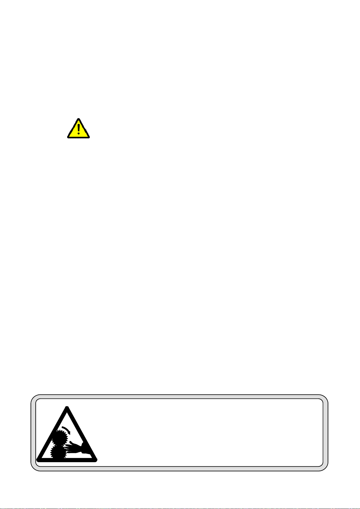
NEVER PUT YOUR HANDS INTO THE
FEED INTAKE BOOT WHILE FILLING
THE PANS.
Switchonthefeederuntilthisfeedisdistributed,thenrepeat
the procedure until the whole line is filled. By doing this :
-- you limit the load on the motor of a long feeder line.
-- atthesametime,youtesttheswitchesandmakesurethat
the feeder line has been properly installed.
-- you become used to the system.
Ifinsteadtherearesmallmarksofrusteitherontheinsideof
the tube as on the auger, we advise to mix the first 5kg of
feedwithaportion(¦1/4l)ofmaizeoil.Thisistoavoidthe
noise and trembling during the starting up.
CONTROL UNIT
The last feeder pan on the line (the control pan) is the most
important one. It must be emptied first because it starts the
next feed supply.
Take care that there are enough birds eating from this pan.
Birds are sensitive to light, moisture, draught and
temperature. They will shun places with an environment
deviating from the average. You can have more light above
the control pan by installing for example a small spotlight
which lightens the control pan only.
Keep the pan free of litter and manure. It has to be the most
attractive pan on the line.
Take care that temperature, moisture, ventilation are
constant at this location.
Morebirdswillfeedfromthecontrolpansifyouinstallthem
at a distance of 2--3m from the end wall. The same remark
goes for the outside line (next to the side walls).
FILLING THE HOPPERS
The drop tube of the feeder line furthest from the bin is
equipped with a level switch.
This level switch controls the feed supply from the bin.
If,forcertainreasons,thelastlineisnot enoughusedbythe
birds,itispossiblethattheotherlinesmightrunempty. This
can be prevented by using a time clock.
Thetimeclockshouldbesetsuchthatthefeederisregularly
emptied or decreased to a low feed level.
However,youcanhelptoensurethatenough birdseatfrom
the last line by taking care of :
-- ventilation
-- house structure
-- insulation
-- litter
-- distribution of feeders and drinkers.
Whenplannedcorrectly,youwillhaveaveryevenspreadof
the birds over the whole floor area of the house.
USING THE SYSTEM WITH ONE DAY OLD CHICKS
1. Suspend the 100kg hopper at the correct height.
The weight of the filled hopper will stretch the main cable
to which the chain is fixed when the installation is new.
The connection between the hopper and the first feeder
tube will then no longer be level. This can result in
premature wear and/or failures.
If necessary, shift suspension one or more links to level
the line.
2. Put ALL pans on the floor before placing the one day
olds. Then scatter the litter around the pans.
Take care that all feed windows open simultaneously
and completely.
Now the suspension cords of the tubes are suitably
stretched.
As the pans sink deeper into the litter after a few days,
the windows will remain completely open.
Thesuspensionsofhopperandcontrolunitmustalsobe
suitably stretched.
3. Warmupthehouseandthelitteratleast24hoursbefore
placing the birds.
Fill all pans with feed.
Switch off the feeder lines as soon as all pans are filled.
Thechicksnowhaveenoughfeedfortwodays.Onepan
with open windows holds about 1,6 kg -- about 0,6kg
with closed windows.
Refill all pans after two days and stop the feeder lines.
Repeat this every day until thebirdsare5--7daysold.
So you get a good control of feed intake during the
important starting phase.
You can now easily switch over to automatic filling by
means of the control pan. The feeder line starts
automatically as soon as this pan is empty. All pans are
filled.
You can feed automatically from the first day on, but
then you must regularly check feed intake atthe control
pan.

ROXELL - 001 - 2111 MINIMAX LINE -- INSTRUCTIONS FOR THE USER
I--5
4. The point in time to operate with closed feed windows
will depend upon the type of feed.
We recommend the 5th. day for free flowing, pelleted
feed -- max. 20 days for difficult flowing (mash) feed.
Winch up the feeder line until all windows are closed.
Attention : all pans are still sitting on the floor !
Birds get used to the lower feed level. Raise the feeder
lines a little some days after closing the feed windows.
Pans swing and the feed is better spread.
Winch up the feeder lines gradually as the birds grow.
The back/neck of the birds (even the smallest) must be
slightly bent over while eating.
Correct operation will help you to prevent feed waste.
USING THE SYSTEM FOR OLDER BIRDS
1. Suspend the lines at the correct height. You will obtain
optimum results when the birds can easily pick the feed
from the deepest part of the pan.
Ifbirdsnecks rest ontheedge ofthepan, thefeederline
is adjusted too high.
Onthecontrary,ifbirdsperchontheedgeofthepan,the
line is adjusted too low.
You will prevent feed waste by keeping the pans at the
correct height !
The correct position of the feed level ring will be found
by experience.
You must consider feed composition, fat content and
type of birds.
Thefollowingfeedleveladjustmentswerederivedfrom
practice :
-- free flowing feed : feed level ring in position 2, 3 or 4
-- difficult flowing feed : feed level ring in position 5,
6or7
Optimumfeedingresultswillbeobtained withadequate
panheight, correctadjustmentofthefeedlevelringand
use of a time clock
Have the pans emptied at least once a day. So the birds
will always get fresh feed.
2. Whenusingpanswitha4strutgrillforducksorturkeys,
add the collar.
-- from 3--4 weeks on (peking ducks)
-- from 6--7 weeks on (turkeys and other ducks)
This will decrease feed wastage.
3. If the birds have been without feed for a considerable
period, you must be very careful when filling up the
feeder lines.
The 100kg. hopper should be filled before starting the
lines. So the transport system has a head start to supply
the hoppers.
Spread some feed on the litter so that the birds do not
rush onto the pans when the augers start.
Anothermethod: winchupthefeederlinessothatbirds
cannot reach the pans. Only then fill up the pans and
lowerthelines:butmakesurethatbirdsdon’tpusheach
other under the pans as they are lowered.
Keep an eye on the feed supply.
Walk along the lines and gently disperse birds.
AT THE END OF A CROP
Have all pans emptied at the end of the crop. Also auger all
feed out of the tubes.
Winch up the complete installation to remove birds and
manure.
NEVER STAY UNDERNEATH WHEN
LOWERING OR WINCHING UP THE
FEEDER LINES. STOP IMMEDIATELY
AT THE SLIGHTEST HITCH.
Take care not to damage the pans (with heavy objects or
machines) when cleaning out the house.
MAINTENANCE
To clean the installation winch up the feeder lines to a
working height of about 1m.
Removepossiblefeedresiduesbyturningthepansacouple
of times 180 degrees around the tubes or by removing the
pans from the grills.
Youcannoweasilycleantherotatingpansoneafteranother
by means of a high pressure cleaner.
Toputbackthepan:takeitinonehand(likeadish)andpush
it into the grill from below.
Withtheother hand,hold thefeed levelringsothatthe grill
cannot go up.
DON’T FORGET TO COVER UP THE CONTROL
PANWITHPLASTIC!
Motors and switches are IP55. This means that they resist
splashing, NOT jets from a high pressure cleaner.
After cleaning, tip the water out of the pans.
Take care that no water remains in the feed intake boot
(corrosion !!!) You can avoid this :
-- by loosening the tube clamp and turning the feed intake
boot with the opening downwards before you use the
high pressure cleaner, or
-- byhangingup thefeed intakeboot,sothatallremaining
water flows away through the hole in the tube. This
method requires an extra suspension point next to the
100kg hopper or fixing the hopper suspension chain to
the feed intake boot.
The pan, made of high quality polypropylene, resists
practically all cleansers and disinfectants.

MINIMAX LINE -- INSTRUCTIONS FOR THE USER ROXELL - 001 - 2111
I--6
If you want to use an aggressive product (**) first contact
your supplier !!
HangtheOPERATIONINSTRUCTIONSataspotinside
the house where it catches the eye.
(**) P.S. Gaseous formaldehyde (formalin), liquid caustic
soda or solution of caustic soda, hypochlorite or chlorine
water cresoles are very corrosive and they will quickly
affect the installation !
WHAT TO DO BEFORE INSTALLING THE NEXT
BATCH OF BIRDS ?
Check operation of your system before placing the birds.
More particularly, take care that :
* all feed level tubes are at the same level (always keep
feed level as low as possible)
* all switches react promptly the control pans are
properly adjusted (low feed level).
* the antiperch wire is still stretched (springs must be
stretched (about 6cm )
* the time clock (when used) is programmed
* there are no leaks in the feed supply system
* there is no old, stale and/or tainted feed in the bin
* the feeder lines are well aligned. Especially the power
unit and the hopper must be well aligned and at the
same level.
PROGRAMMED FEEDING
Withthefeedingsystemitispossibletoprogrammefeeding.
This means : feeding according to a programme set on a
time--clock.
It also means : to make sure that no feed is supplied during
certain periods.
Pans are emptied between meals (if you want this).
ADVANTAGES :
* 0 to 4 points better feed conversion :
-- birds waste less feed (lower feed level).
-- fresh feed available at several preset times = more
resting periods ; a better digestion ; more appetite.
-- you can observe birds better during the meal. Sick
birds are more easily identified.
* the system works more regularly (less switching
on/oft).
* less risk that the system runs empty. You have better
control of the system’s performance.
HOW TO PROGRAMME :
There are many ways.
Your house, the breed of birds, the feed you choose and the
possibilities you have as a user, determine the best
programme.
Thepurposeisalwaysthesame:dividethe24hourperiodin
4 segments of 6 hours.
Eachsegmenthas3periods:ischaracterized byaperiodof:
SYSTEM IN OPERATION
PLENTY OF FEED
AVAILABLE
SYSTEM OUT OF
OPERATION FEED IN
PAN IS EATEN
SYSTEM OUT OF
OPERATION : PANS
ALMOST OR
COMPLETELY
EMPTY
0.0005.0006.00
1
1
1
12
2
2
2
3
3
30.0
0
05.00
06.0
0
18.0
0
12.00
3
Our experiences have lead to the following
recommendations of use :
-- Set the programme right from the beginning .
-- Seethatpansareemptiedforthefirsttimeafter3weeks,
not sooner. Divide the 24 h in 4 segments of 6 hours.
-- Since the birds do not eat for 1/2 hour to 2 hours, there
ismoreactivityatthestartofanewsegment.Thismeans
that the occupation per pan and per drinker should not
exceed our recommendations.
-- You have to gain experience. Do not expect to obtain 4
points better feed conversion from the first time.
-- During the summer it might get colder in the house
during the night. Adjust your programme by having the
system operate longer during the night segment.
-- Donotprogrammewithpoorqualitybirds.Interruptthe
programme in case of illness and do not let the system
become empty.
-- Influences of season, breed, age, house climate, feed
also play a role.
To get the maximum profit out of your system, you should
develop your own programme according to the
circumstances.
For any further advice, contact ROXELL NV .

ROXELL - 001 - 2111 MINIMAX LINE -- INSTRUCTIONS FOR THE USER
I--7
MAINTENANCE INSTRUCTIONS
Switch off the current first. Use protection
DANGER
3-monthly
6-monthly
Yearly
ACTIONS IN GREY BACKGROUND MUST BE DONE BY A TECHNICALLY TRAINED PERSON.
1. Power unit
-- Make fan dust-free X
-- Check possible damages to electrical wiring X
2. Poultry intake boot with sensor
-- Check sensor X
3. 100kg hopper (lines)
-- Check level switch X
4. Suspension
-- Check operation of (central) winch X
-- Check operation of (central) winch. Grease after cleaning. X
-- Check connection of cable X
-- Check connection of pulleys X
-- Check suspension of tubes and motors X
-- Keep suspension cord/cable in tension X
5. Poultry perch cable above the tubes/elbows
-- Check cable X
6. Pans
-- Check possible damages of pans X
7. Sensors/switches
-- Check operation of safety switch or sensor. X
-- Check electrical wiring X
8. Control pan
-- Remove the pan and clean the inside tube X
-- Clean (dry) sensor head and central tube X
-- Check switch of control units X
9. Lines/circuits
-- Check screws and bolts in the system after the first month and after each batch.
Tighten if necessary. X
-- Keep tubes level. X
-- Remove all feed from the system when the system will be out of use for a period. X

MINIMAX LINE -- INSTRUCTIONS FOR THE USER ROXELL - 001 - 2111
I--8
TROUBLE SHOOTING GUIDE
Switch off the current first. Use protection
DANGER
ACTIONS IN GREY BACKGROUND MUST BE DONE BY A TECHNICALLY TRAINED PERSON.
PROBLEM CAUSE CORRECTIVE ACTION
1.None of the feeder
lines run. No current. Replace defective fuses or reset circuit breakers.
Check current supply to the house.
Defective clock. Replace defective clock.
Time clock not properly set. Readjust tabs.
2.One/more lines do
not run.
Pans are empty
Wires from motor damaged. Measure current in motor wires. Replace wires if
defective.
Thermal protection of motor switched
off. See points 3. & 4. Reset motor overload button.
Defective control unit switch. Replace defective control unit switch box.
Control unit not functioning properly. Adjust level of control pan. Hang an extra lamp above
it. Check temperature. Control unit must be the most
attractive one, especially the control unit of the feeder
line below the Flex--Auger control unit.
Defective sensor/minimum switch
control unit or 100kg hopper. Check control unit sensor or switch. Replace if
necessary.
3.Motor is often
overloaded. Oil on auger overloads the motor. Clean the auger by running repeatedly 25kgs of feed
through the line.
Notenoughcurrentsupplyto themotors. Checkcurrentsupplyatmotorlocation.Startthemotor.
Measure start current on motors. Wiring must be thick
enough to guarantee good operation of the system.
Object blocks the auger. Motor runs,
then stalls. Feed sticks to the tubes. Checkiftherearenoobjectsintheboot,thecontrolunit
and the drop holes of the feeder pans. Remove any
objects.
4.Auger stalls. Anchor bearing worn out or broken. Replacebearing.Gentlyslideaugerbackintothe tubes.
Don’tletitjumpback:yourfingerorthe bearingcould
be damaged.
Auger not enough stretched. Shorten the auger.
Object blocks the auger. Remove the object.
5.Tubes / boot wear rap-
idly, much noise
when system runs.
Auger kinked or bent at the wear point.
Auger end overlaps the anchor end. Makesurenottokinktheaugerwhenusinggrippingpli-
ers. Auger must not overlap the anchor end.
6.Not enough feed
supplied to fill up
the lines.
Flex--Auger drop holes are too small or
point upwards. Make holes wider/turn tubes with holes downwards.
Flow regulator in boot of feed supply
system blocks passage of the feed. Adjust flow regulator to get a higher capacity.
Flex--Auger capacity is too low. Check the capacity of the Flex--Auger according the
specifications.
Check the installation of the Flex--Auger.
Not enough time set on the time clock. Extend operation time per meal.
7.Feed drops directly
on the adjuster ring
of the grill.
Pan not installed over the hole. Remove the top support. Install the pan ass’y over
the hole and the lips.

ROXELL - 001 - 2111 MINIMAX LINE -- INSTRUCTIONS FOR THE USER
I--9
PROBLEM CAUSE CORRECTIVE ACTION
8.Windows are open
and feed level is
too low.
Some windows are actually closed. Adjust height of feeder line until all windows
completely open and close simultaneously.
9.Windows are closed
and feed level is
too high.
Adjuster ring set too high. Adjust height. See OPERATOR’S GUIDE.
Notallwindowsareclosedorcompletely
closed. Adjust height of feeder line until all windows
completely open and close simultaneously.
10.Windows are
closed and feed
level is too low.
Adjuster ring set too low. Adjust height. See OPERATOR’S GUIDE.
Feeder line not winched up high enough. Winch up feeder line higher until all pans
simultaneously are clear of the litter.
11.Hopper 1 is empty
while the feed
level in the second
hopper
corresponds with
the position of
the level switch
Birds massively move to one side of the
house,i.e.dependinguponthepositionof
the sun.
A. The problem occurs sporadically :
You can solve the problem by changing the round
hole in the Flex--Auger tube above hopper 1 into a
rectangular one. Install two outlet drops above
hopper 1 (see fig. 3.) if necessary, so that more
feed drops into hopper 1. Install the level switch
low in hopper 2 (see fig. 2.). Install and adjust
drop tubes to all hoppers high enough.
B. The problem occurs regularly :
Install a level switch high in each hopper. Install
the level switch low in the last hopper. Install and
adjust the drop tube high, so that the feed in tube
A (over switch level) is carried to hopper 2.
Drop tube installed and
adjusted high.
Level switch installed
low.
Hopper 1
Hopper 2
FIGURE 1. FIGURE 2.
A
Hopper 2
Case a.
Large feed reserve (A) in
case b.
Hopper 1
FIGURE 3.

MINIMAX LINE -- INSTRUCTIONS FOR THE USER ROXELL - 001 - 2111
10
OPERATOR’S GUIDE
For floor feeding -- from day--old chicks to broilers, turkeys (12kg) layers (also breeders), ducks
Weeks
Age of
birds 0
open feed windows
12 3 45
pans full
(manual operation)
closed feed windows
BROILERS
LAYERS
(rearing)
Winch up
EASY START
automatic operation
on control pan
6
AVOID FEED WASTAGE = ADJUST FEEDER
HEIGHT
Lower
add feed saver collar (with 4--strut grill)
DUCKS
TURKEYS
DUCKS TURKEYS
Winch up
TURKEYS
0511 00104661

ROXELL - 001 - 2111 MINIMAX LINE -- INSTRUCTIONS FOR THE USER
11
Number of birds per pan (*)
1Broilers 50 100 (max. 150kg/pan)
2Turkeys (0 14 weeks) 5070
3Turkey poults -- rearing (06 weeks) 12kg 60 70
4Free range layers (also breeders) 26(EC) 45
5Free range layers rearing (also breeders) 26 45
6Ducks 60 70
7Guinea fowls, pheasants 50 90
8Quails 300
*(heavy birds/light birds) (poor ventlation/good ventilation)
2111 00104661
(FIXED INTERMEDIATE) CONTROL PAN
For controlled feeding : have the pans emptied once (to several times) a day.
OPERATOR’S GUIDE
-- use from :
1 week (layer chicks)
2 weeks (turkey chicks)
-- do not use it constantly
-- use as WARNING !
AVOID DRAUGHTS
Poultry perch system (for partial brooding)
AVOID DARKNESS
* The last day : run the tubes empty and let the birds empty the pans as much as possible.
* Remove possible feed residues by turning the pans a couple of times180 degrees around the
tubes or by removing the pans from the grills.
* Protect electrical components against water.
* Clean the whole system by means of a high--pressure cleaner (max. 100 Bar).
* When using aggressive detergents or disinfectants consult your supplier.
CLEANING
= THE MOST USED PAN
CHECK THE SUSPENSIONS OF THE 100 KG HOPPER AND THE
CONTROL UNIT AFTER HEATING UP THE BUILDING. BOTH SUS-
PENSIONS MUST BE WELL STRETCHED.

Inbouw
v
Declara
t
II.1.B)
Fabrikan
t
Roxell, I
n
Tel: +32
5
Fax: +32
Verklaar
t
Declares
MINIM
A
Automat
i
Automat
i
Waarop
d
-de v
Co
m
-de g
121
0
Het is ve
r
wordt in
g
Tevens v
e
nationale
wijze va
n
eigendo
m
Relating
t
-The
Co
m
- The
121
0
This pro
d
incorpor
The man
u
authoriti
e
method o
p
rejudice
machiner
y
v
erklarin
g
betref
fe
tion of incorporat
i
t
/Manufacturer:
n
dustrielaan 13, 9990
50 72 91 72
50 71 67 21
t
geheel onder eigen
v
on its own responsib
i
A
Xline/HaiKoo
N
i
sch pannen voedersy
s
i
c pan feeding syste
m
d
eze verklaring betre
k
olgende richtlijnen:
2
m
patibiliteit).
eharmoniseerde Eur
o
0
0:2010; EN 60204-1
r
boden bovengenoe
m
g
ebouwd in overeen
s
e
rbindt de fabrikant (
o
autoriteiten de relev
a
n
doorgifte is digitaal.
m
srechten van de fabr
i
(
t
o this declaration, is
following directives
2
m
patibility).
harmonised Europea
n
0
0:2010; EN 60204-1
d
uct must not be pu
t
ated has been decla
r
u
facturer (or its agent
e
s, to provide the rele
v
f transmission will b
e
the manufacturer’s i
n
ry
.
f
ende niet voltooid
e
i
on of partl
y
com
p
Maldege
m
v
erantwoordelijkheid
i
lity that the product:
N
r: 002…/009…
s
teem voor slachtkui
k
m
for broilers.
k
king heeft, in overee
n
2
006/42/EG (Machin
e
o
pese Normen: EN IS
O
:2006
m
d product in gebr
u
stemming met de b
e
o
f zijn gemachtigde)
a
nte informatie over
d
De wijze van infor
m
i
kant van de niet volt
o
(
NL)
conform
2
006/42/EC (Machin
e
n
standards: EN ISO
:2006
t
into service until t
h
r
ed in conformity w
i
) also undertakes, at
t
v
ant information con
c
e
digital. The manner
n
tellectual property r
i
(EN)
e
machines
(Richtli
j
p
leted machiner
y
(
D
dat het product:
k
ens.
n
stemming is met:
e
richtlijn); 2004/108/
E
O
13857:2008; EN 3
4
u
ik te stellen voorda
t
e
palingen van de Ma
zich om op met rede
n
d
eze niet voltooide m
a
m
atieverschaffing laat
o
oide machine onver
l
e
ry Directive); 2004/
1
13857:2008; EN 349
:
h
e machinery into
w
i
th the provisions of
t
he duly reasoned req
u
c
erning this partly co
m
in which the inform
a
i
ghts concerning the
p
j
n 2006/42/EG, Bijla
g
(
D
irective 2006/42/E
C
E
G (Elektromagnetis
c
4
9:1993 + A1:2008;
E
t
de machine waari
n
a
chinerichtlijn is ver
k
n
en omkleed verzoek
a
chine door te geven.
de intellectueel-
l
et
1
08/EC (Electromag
n
:
1993 + A1:2008; E
N
w
hich it is to be
the Machinery Dir
e
u
est of the national
m
pleted machinery.
T
a
tion is provided does
p
artly completed
g
e I
I
.1.B)
C
, Annex
c
he
E
N ISO
n
het
k
laard.
van de
De
n
etic
N
ISO
e
ctive.
T
he
not
Plaa
t
…
…
Dhr.
Man
a
EG-
EC-
d
Wij/
W
Ver
k
Decl
a
In ee
over
e
Has
b
p
res
c
Dez
e
met
u
b
ew
e
This
mar
k
s, Datum / Place, Da
t
…
…………………
…
Gino Van Landuyt
a
ging Directo
r
“This part m
a
v
erklarin
g
van ov
e
d
eclaration of con
W
e__________
_
(naam installate
u
_
_______________
_
_
_______________
_
(volledig adres
e
laren geheel onder e
i
a
re completely on o
w
_____________
_
(naam machine/
n
n
installatie te hebbe
n
e
enstemming met de
b
b
een incorporated in
c
c
riptions of Roxell N
V
_____________
_
(plaats, datum/p
e
verklaring betreft ui
t
u
itsluiting van de late
r
e
rkingen.
declaration concerns
k
et, excluding compo
n
t
e :
Maldegem,
01/0
…
……..
a
y only be filled out if a
l
e
reenstemmin
g
(R
i
formit
y
(Directive
2
_
____________
_
u
r/name fitter)
_
________________
_
_
________________
_
e
n land/complete add
r
i
gen verantwoording
w
n justification that
_
_____________
_
n
ame machinery)
n
ingebouwd geheel
v
b
epalingen van de M
a
c
onformity with the
p
V
_
____________
_
lace, date)
t
sluitend de machine
i
r
door de eindgebrui
k
solely the machinery
n
ents added and/or m
o
1/2012
l
l buil
t
-in subparts are d
e
i
chtlijn 2006/42/EG,
B
2
006/42/EC, Annex I
I
_
____________
_
_
________________
_
_
________________
_
r
ess)
de
_
_____________
_
(nummer CE-l
a
v
olgens de Roxell-vo
o
a
chinerichtlijn.
p
rovisions of the Mac
h
_
_____________
_
(naam, handt
e
i
n de toestand waarin
k
er toegevoegde com
p
in the condition in w
o
difications made lat
e
e
livered by Roxell”
B
ijlage I
I
.1.A)
I
.1.A)
_
___________
_
_
________________
_
_
________________
_
_
_____________
_
a
bel/number CE-labe
l
o
rschriften en in
h
inery Directive and
t
_
_____________
_
e
kening/name, signat
u
zij in de handel is ge
p
onenten en/of verric
h
hich it has been brou
g
e
r by the end user.
_
_
_
_
_
_
l
)
t
he
_
_
u
re)
bracht,
h
te
g
ht onto the
00105304
SPECIMEN

EG-verklaring van overeenstemming (Richtlijn 2006/42/EG, Bijlage II.1.A)
EC-declaration of conformity (Directive 2006/42/EC, Annex II.1.A)
Fabrikant/Manufacturer:
Roxell, Industrielaan 13, 9990 Maldegem
Tel: +32 50 72 91 72
Fax: +32 50 71 67 21
Verklaart geheel onder eigen verantwoordelijkheid dat het product:
Declares on its own responsibility that the product:
Winching system Nr: 00102368 / 00102087
Liersysteem voor voer- en drinklijnen; manueel en gemotoriseerd
Winching system for feed- and drink lines; manual and motorised
Nummer CE-label/number CE-label :______________________________________________
Waarop deze verklaring betrekking heeft, in overeenstemming is met:
-de volgende richtlijnen: 2006/42/EG (Machinerichtlijn); 2004/108/EG (Elektromagnetische
Compatibiliteit).
-de geharmoniseerde Europese Normen: EN ISO 13857; EN 349:1993 + A1:2008; EN ISO
12100:2010; gemotoriseerd: EN 60204-1:2006
Deze verklaring betreft uitsluitend de machine in de toestand waarin zij in de handel is gebracht, met
uitsluiting van de later door de eindgebruiker toegevoegde componenten en/of verrichte
bewerkingen.
(NL)
Relating to this declaration, is conform
-The following directives 2006/42/EC (Machinery Directive); 2004/108/EC (Electromagnetic
Compatibility).
-The harmonised European standards: EN ISO 13857:2008; EN 349:1993 + A1:2008; EN ISO
12100:2010; motorised: EN 60204-1:2006
This declaration concerns solely the machinery in the condition in which it has been brought onto the
market, excluding components added and/or modifications made later by the end user.
(EN)
Plaats, Datum / Place, Date : Maldegem, 01/01/2012
………………………………..
Dhr. Gino Van Landuyt
Managing Director
00105502
SPECIMEN

Table of contents
Other Roxell Farm Equipment manuals

Roxell
Roxell Dozit User manual

Roxell
Roxell SparkCup User manual

Roxell
Roxell Bridolay User manual

Roxell
Roxell Blu'Hox User manual

Roxell
Roxell Optimax User manual

Roxell
Roxell KOOZII 018 Series User manual

Roxell
Roxell LAICA User manual

Roxell
Roxell HaiKoo User manual

Roxell
Roxell FLEX-AUGER FA 55 User manual

Roxell
Roxell CoMeo User manual
Popular Farm Equipment manuals by other brands

Suevia
Suevia KRAZZMAXX IV Mounting and operation instructions

IntelligentAg
IntelligentAg Engage Zone Control Maintenance manual

horsch
horsch Pronto 6 AS operating instructions

Krone
Krone Big Pack 890 Original operating instructions

Brinsea
Brinsea TLC-40 User instructions

Toro
Toro 138-2998 installation instructions