FPS FNG Series User manual

OWNER'S MANUAL
English
EN
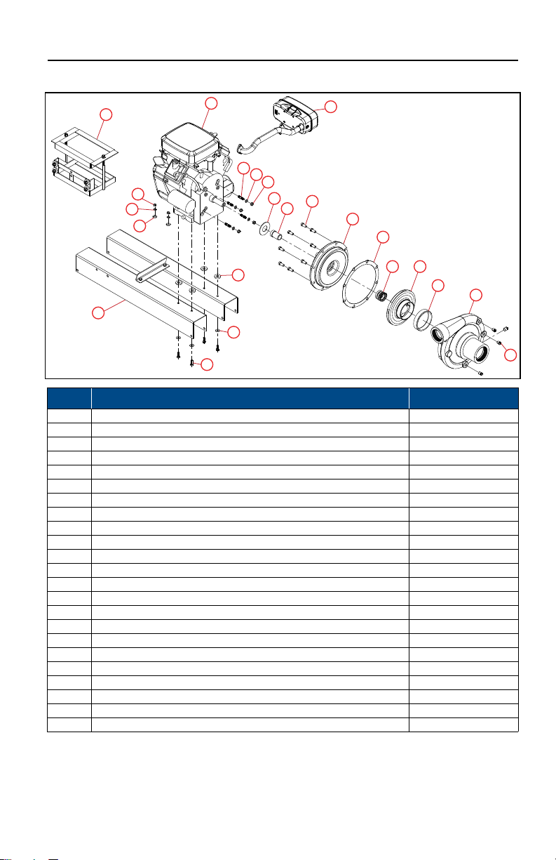
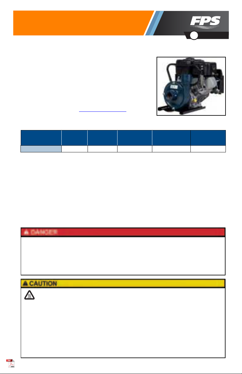
FNG Series Centrifugal Pumps
The FNG Series centrifugal pumps are ideal irrigation or utility pumps, whether as portable units or fixed installations. The centrifugal gas engine pumps can be used in mining, irrigation, construction, and other heavy-duty applications.Refer to the engine manual for instructions and safety details.This product is covered by a Limited Warranty for a period of 1 year from the date of original purchase by the consumer. For complete warranty information, refer to www.FranklinWater.com.SpecificationsSAFETY INSTRUCTIONSThis equipment should be installed and serviced by technically qualified personnel who are familiar with the correct selection and use of appropriate tools, equipment, and procedures. Failure to comply with national and local electrical and plumbing codes and within FPS recommendations may result in electrical shock or fire hazard, unsatisfactory performance, or equipment failure.Know the product’s application, limitations, and potential hazards. Read and follow instructions carefully to avoid injury and property damage. Do not disassemble or repair unit unless described in this manual.Failure to follow installation or operation procedures and all applicable codes may result in the following hazards:Pump TypeItem NumberSuctionDischargeMax TemperatureMax. PressureFNG-23V End Suction902612233 in. (7.62 cm)2-1/2 in. (6.35 cm)212 °F (100 °C)125 psiRisk of death, serious injury, or property damage.
•Do not use to pump flammable, combustible, or explosive fluids such as gasoline, fuel oil, kerosene, etc.•Do not use in explosive atmospheres or hazardous locations as classified by the NEC, ANSI/NFPA70.•Do not handle a pump or pump motor with wet hands or when standing on a wet or damp surface, or in water.•When a pump is in its application, do not touch the motor, pipes, or water until the unit is unplugged or electri-
cally disconnected.Risk of bodily injury or property damage.
•This equipment must not be used by children or persons with reduced physical, sensory or mental abilities, or lacking in experience and expertise, unless supervised or instructed. Children may not use the equipment, nor may they play with the unit or in the immediate vicinity.•An inoperative or malfunctioning pump could lead to flooding, resulting in personal injury or property damage.•Operation of this equipment requires detailed installation and operation instructions provided in this manual. Read entire manual before starting installation and operation. End User should receive and retain manual for future use.•Keep safety labels clean and in good condition. Keep work area clean, well-lit, and uncluttered.•Wear safety glasses while installing or performing maintenance on the pump.

INSTALLATIONTypical Installations2INSTALLATIONTypical InstallationsPump Location•Install the pump in a clean, dry, and ventilated location shielded from direct sun and precipitation.•Provide adequate room for future servicing, protection from freezing temperatures, flooding, and equipment drainage.•Bolt unit down evenly on a good foundation, preferably concrete.•Install as close as possible to water source to minimize piping length and unnecessary hose friction losses while maximizing available pressure.Piping Instructions•Properly support suction and discharge piping, including independently from the pump near the casing, to avoid strain on the pump.•Use an opposing pipe wrench on suction and discharge bosses when threading pipes.•Use pipe thread sealant.•Do not over-tighten piping connections.•Do not use piping smaller than the inlet size.•Only use enough pipe length necessary to reach the discharge or suction inlet, increasing the pipe/hose size only if long line lengths are required.•Avoid using restrictive reducing fittings and unnecessary bends in lines.1Suction Primer3Suction Hose/Pipe5Water Hose7Elbow2Check Valve4Strainer6Funnel8Foot Valve with Strainer
1
2
2
3
3
4
5
6
7
8

INSTALLATIONPiping Instructions3Suction Line1.Install a new, clean, non-collapsible pipe or hose, making sure piping rises vertically or continually from the water source to the pump inlet connection with no high spots.•Avoid attaching an elbow directly to the inlet.•Do not use concentric fittings or pipe reducer bushings to increase the size of the pipe.•A straight pipe length at the suction entrance should be at least six times the suction diameter. •When using an eccentric reducer, be sure to install it with the flat side up.2.For flooded suction and booster applications, install an isolation ball or gate valve between the water source and the suction inlet to facilitate servicing the pump.•When not servicing the pump, keep this valve wide open to avoid friction loss.3.When connecting to a tank, install a baffle between the incoming liquid and the pipe inlet to pre-
vent air from entering the pipe. 4.For liquids containing solids, install a strainer with a free opening area at least 3 times the area of the pipe. 5.Submerge the end of the pipe in the fluid a distance of at least four to five times the diameter.6.If not using an ejector, exhauster, or vacuum pump, install a flap-type foot valve with a passage opening at least the same area as the pipe.IMPORTANT: Do not use a foot valve if there is high static head.NOTE: In high-head installations, severe water hammer results at the foot valve when the pump is quickly shut down. 7.Tighten all connections thoroughly to avoid air leaks.Discharge Line1.Install a new, clean discharge pipe or hose suitable for pumping pressures.•Use standard hose capable of handling the maximum pump pressure. •Seal all pipe joints and connections with appropriate sealing compound and thoroughly tighten. •Use the minimum length of line required in your application. •Avoid unnecessary bends, lengths, elbows, or expansion/reduction fittings if they are not abso-
lutely necessary. 2.If expanding a discharge line size, use concentric fittings.•Do not use standard pipe reduction fittings if possible. 3.Install a check valve and a gate valve in the discharge line with the check valve between the gate valve and the pump.4.Tighten all connections thoroughly.

OPERATIONPriming the Pump4OPERATION Priming the Pump1.For systems with an ejector or exhauster:•Make sure there is a tight valve located in the discharge line close to the pump.•Attach the ejector to the highest point in the pump casing to remove the air from the pump and suction line.•Operate the ejector to fully evacuate the air from the pump before starting.•If the pump does not deliver water within seconds, stop the pump and prime again.2.For a system with a vacuum pump, use it to remove the air from the pump casing and suction pipe.3.For a system utilizing a foot valve:•Fill the suction line, pump casing, and discharge pipe to a foot above the pump discharge.•Leave an air vent at the top of the pump casing until water flows through it without any air. •If there is an unusual amount of air, leave the vents on the top of the casing or connected to the drain pipes slightly open during operation.NOTE: If part of the suction line is horizontal, several minutes may pass before the air gets to the vent hole. •Close the vent hole and start the pump. NOTE: A tight foot valve will keep the pump constantly primed for automatic operation.Starting the Pump1.Check the engine manual for engine preparation and normal operating procedures. 2.Check the engine oil level before starting.3.Close the gate valve in the discharge line.4.Open the gate valve gradually as the engine approaches full speed.NOTE: After the pump has been in operation and the discharge line completely filled, it is no lon-
ger necessary to close the valve for starting.5.If the pump does not deliver water within seconds, stop the engine and prime the pump again.Risk of severe injury or death by high temperatures or pressurized fluids.
•Do not continuously run pump against closed discharge. Release all system pressure before working on any com-
ponent. Risk of damage to pump or other equipment.
•Do not run pump dry. Running dry will cause serious damage to the pump.•Never throttle the pump from the suction side.•Do not change the engine governor speed setting, as engine damage may result. •Avoid bends in hose lines during operation.

MAINTENANCEPeriodic Maintenance5MAINTENANCEPeriodic Maintenance1.Check the pump periodically for loose or rubbing parts. 2.Service immediately if any unusual noise, leaks, or vibrations develop. 3.If applicable, inspect the foot valve for leaks.4.Drain the pump should it be subjected to freezing temperatures:•Remove the drain plug at the bottom of the pump casing.•Remove the vent plug at the top of the casing.5.Check if the wear rings need replaced.NOTE: On some models, the rings provide a close-running clearance to reduce liquid leaking from the high-pressure side to the suction side. The rate of wear depends on the type of liquid pumped.6.Refer to the engine manual for lubrication.Mechanical Seal Replacement1.Unbolt and remove the volute case.2.Remove the impeller by rotating it counterclockwise using a suitable strap wrench. IMPORTANT: Be careful not to damage the impeller.NOTE: It may be necessary to remove one spark plug and push one foot of 1/4" rope into the cyl-
inder to lock the engine for impeller removal. Remove the rope once the impeller is off.3.Unbolt and remove the adapter plate from the engine.4.Push out the ceramic stationary portion of the seal from the backside of the adapter plate towards the impeller end.5.Clean all parts and inspect them for wear.6.Replace any damaged or worn parts7.Apply Loctite 7649 primer to engine shaft journal and inside of shaft sleeve. 8.Apply a thin ring of green Loctite 648 retaining compound around inside leading edge of shaft sleeve and a line along the engine shaft journal.9.Slide the shaft sleeve onto engine shaft and rotate sleeve at least two times before seating against engine shaft shoulder.10.Wipe off excess Loctite and let stand for 3 minutes. 11.Apply P-80 lubricant to the shaft seal boot and bellows. IMPORTANT: Keep ceramic face clear from residue or debris. 12.Slide boot and bellow assembly onto engine shaft seating against ceramic stationary face.13.Use an Loctite 243 between the shaft and impeller. 14.Reassemble impeller onto engine shaft.IMPORTANT: Impeller must turn freely without rubbing.

MAINTENANCETroubleshooting6TroubleshootingProblemProbable CausesCorrective ActionLittle or No Dis-
chargePump is not primed: air or gases in pumpageCheck suction line and foot valve for leaks. Make sure that water level has not dropped to uncover suction inlet. Prime pump.Speed too lowCheck engine speed and correct.Suction lift too greatMove pump closer to water level.Discharge too highPump not correct for application.Reduced capacity and/or headAir leaks in suction lineEnsure all connections are well sealed and piping is sound.Clogged impellerClean out impeller.Foot valve strainer too small or cloggedClean or replace foot valve.Excessively worn impeller or wear ring.Replace impeller.Speed too lowCheck engine speed and correct.Excessive suction lift or losses; NPSHA too low for the pumpLocate pump closer to the water source, increase pipe size, or resize pump.Pump loses primeAir leaks in suction lineEnsure all connections are well sealed and piping is sound.Pump is not primed: air or gases in pumpageCheck suction line and foot valve for leaks. Make sure that water level has not dropped to uncover suction inlet. Prime pump.Casing gasket defectiveReplace part.Worn shaft sealReplace part.Excessive suction lift or losses; NPSHA too low for the pumpLocate pump closer to the water source, increase pipe size, or resize pump.Worn wear ringsReplace parts.Excessive Power ConsumptionSpeed too highDecrease engine speed.Specific gravity or viscosity of liquid too highPump not correct for application.Excessive Noise and VibrationSuction and discharge pip-
ing not properly sup-
ported and anchoredAnchor piping.CavitationCheck NPSH. NPSH (net positive suction head) is the total suction head in feet of liquid (absolute) less the vapor pressure of the liq-
uid in feet (absolute).MisalignmentSettling, seasoning, or springing of the foundationCorrect.Pipe strains distorting or shifting the machineCorrect misalignment and add more support.Shifting of the building structure due to variable loading or other causesCorrect misalignment and add more support.

MAINTENANCEReplacement Parts7Replacement Parts
1
29
10
4
3
5
8
7
6
11
12
14 15
16
17
18
19
19
20
21
22
23
ItemDescriptionOrder Number1Pump Case3054570012Impeller3054570123Motor Adapter3054570034Wear Ring (Suction)3054570045Shaft Sleeve, Mechanical Seal3054570056Base, Engine Frame3054590247Battery Holder Assembly3054570088Muffler3054570139Mechanical Shaft Seal30545701110Case Gasket30545700911Engine B/S 23 hp20194212Pipe Plug 1/4-inch (3 Required)30546302013Pipe Plug 3/8-inch (1 Required)30546317514Water Slinger30545701015Hex Bolt - Volute (8 Required)30546318316Hex Nut - Engine (8-Pack)30546303317Lockwasher - Engine (8-Pack)30546313518Hex Bolt - Motor Base (4 Required)30546311119Washer - Motor Base (4 Required)30546324720Lockwasher - Motor Base (4 Required)30546309221Hex Nut - Motor Base (4 Required)30546306222Threaded Stud (4 Required)30546309323Spacer (4-Pack)305463215

For technical assistance, parts, or repair, please contact:
106742101 Rev. 002 08/22 Copyright © 2022, Franklin Electric, Co., Inc. All rights reserved.
800.348.2420 |franklinwater.com
This manual suits for next models
2
Table of contents
Other FPS Water Pump manuals
Popular Water Pump manuals by other brands

Vortech
Vortech MP60 Setup guide

Grundfos
Grundfos NK Series Installation and operating instructions

EINHELL
EINHELL Neptun NRP-E 40 operating instructions

EINHELL
EINHELL BG-DP 3730 Original operating instructions

Grundfos
Grundfos SPO Series Installation and operating instructions

Intex
Intex Krystal Clear CS7221 owner's manual

Grundfos
Grundfos Sololift2 C-3 Installation and operating instructions

GORMAN-RUPP
GORMAN-RUPP GHS Series Installation, operation and maintenance manual

MULTIQUIP
MULTIQUIP QP2TZ Operation and parts manual

ARVEN
ARVEN TURBO-LG operating instructions

Magnum
Magnum MTP6000S3 operating manual

Speck
Speck P55/150-130G operating instructions