9
4. SOLVENT CEMENTING JOINTS
The flexible discharge pipe connector and inlet piping are joined
to the PowerSewer® system with solvent cement joints for easy,
cost-eective, liquid-tight connections. To ensure proper connections,
carefully follow these instructions.
WARNING
Solvent cements and primers for PVC pipe
and fittings are flammable. Extinguish all
smoking materials, flames or other ignition
sources in working and storage areas. Avoid
eye and unnecessary skin contact with all
cements, primers, and solvents. Ingestion
or intentional inhalation of vapors can
cause severe personal injury or death.
Additional safety precautions may apply; consult solvent cement,
primer or solvent manufacturers for more information.
4.1 Preparing Joints
Wipe away all loose dirt and moisture from the pipe and fitting
surfaces with a clean, dry, cotton rag.
4.2 Pre-Connection Inspection
Check the joint to make sure there is an interference fit between
the pipe and fitting. This is necessary for proper fusion of the joint.
To check, lightly push the pipe into the fitting. Do not use force.
Interference between the pipe and fitting should occur between 1/2" of
socket depth, “full interference fit,” and the socket bottom, “net fit.”
NOTICE Do not use force when checking interference fit.
Do not use components that do not fit properly.
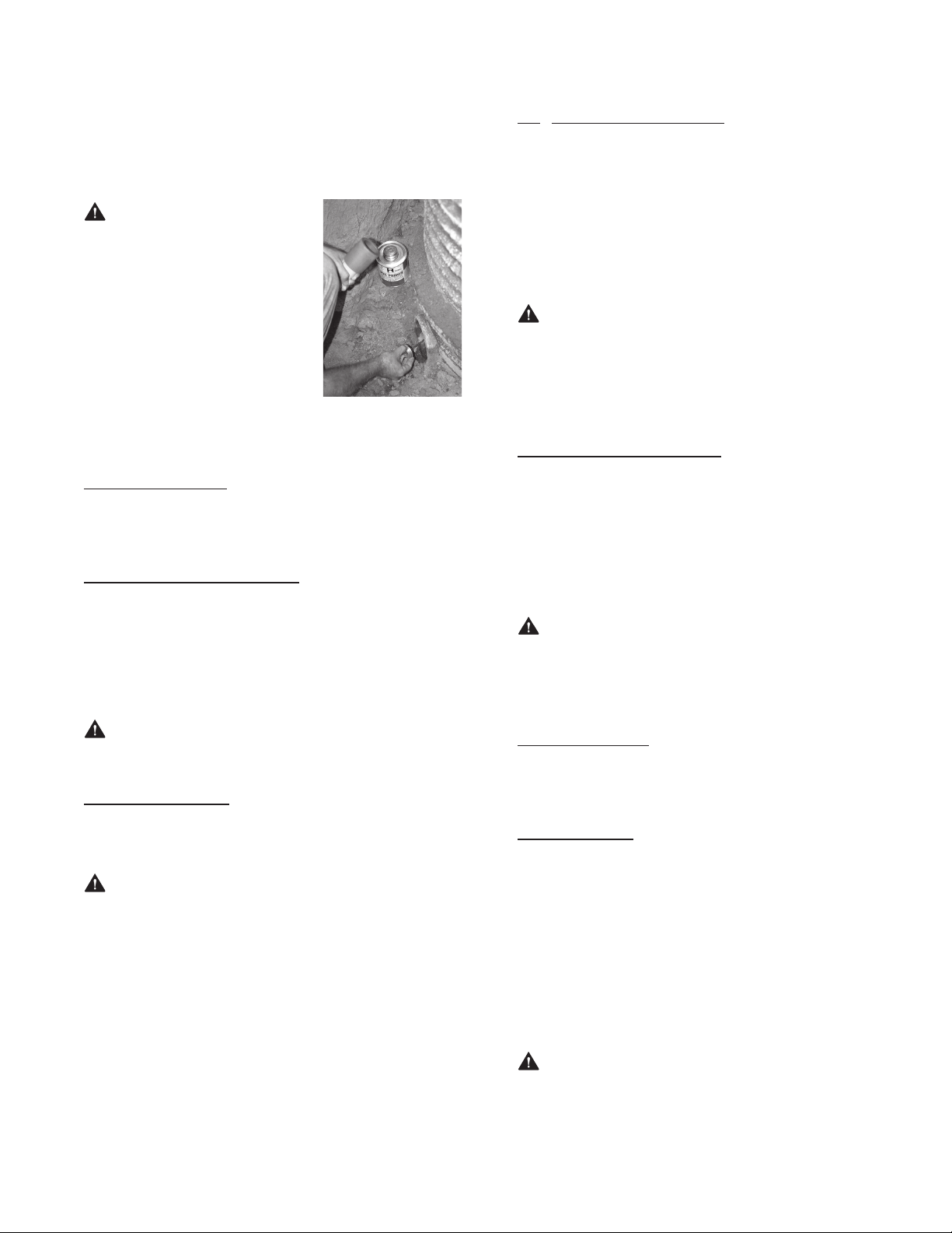
4.3 Applying Primer
Primer is necessary to penetrate and soften both the pipe and the
fitting surfaces in order for the solvent cement to properly bond.
NOTICE The most frequent cause of joint failure is
insucient application of primer and solvent cement. This results in
inadequate solvent penetration and softening of bonding surfaces
during the solvent welding process.
Using a brush or applicator sized no less than 7/8" diameter, apply a
liberal coat of primer with a scrubbing motion to the fitting socket
until the entire surface is softened and semi-fluid. This may take
5 to 15 seconds depending on the temperature. Lower temperatures
will increase the required time. Apply the primer to the pipe in the
same manner. Apply a second coat to both the fitting socket and pipe.
Check solvent penetration and softening by scratching the primed
surfaces. A few thousandths of an inch of the fitting’s surface should
be semi-fluid. Apply another coat of primer if necessary.
4.4 Applying Solvent Cement
Solvent cement must be applied immediately to the primed surfaces
before the primer dries, in an alternating three-coat application. Using
a brush or applicator sized no less than 7/8" diameter, apply a liberal
coat of solvent cement to the primed pipe bonding surface. Then
apply a light to medium coat to the primed fitting socket. If a “net fit”
was experienced during the Pre-Connection Inspection, section 4.2,
apply an additional coat of solvent cement to the pipe surface.
NOTICE The most frequent cause of joint failure is
insucient application of primer and solvent cement. This results in
inadequate solvent penetration and softening of bonding surfaces
during the solvent welding process. Make sure to apply the solvent
cement before the primer dries.
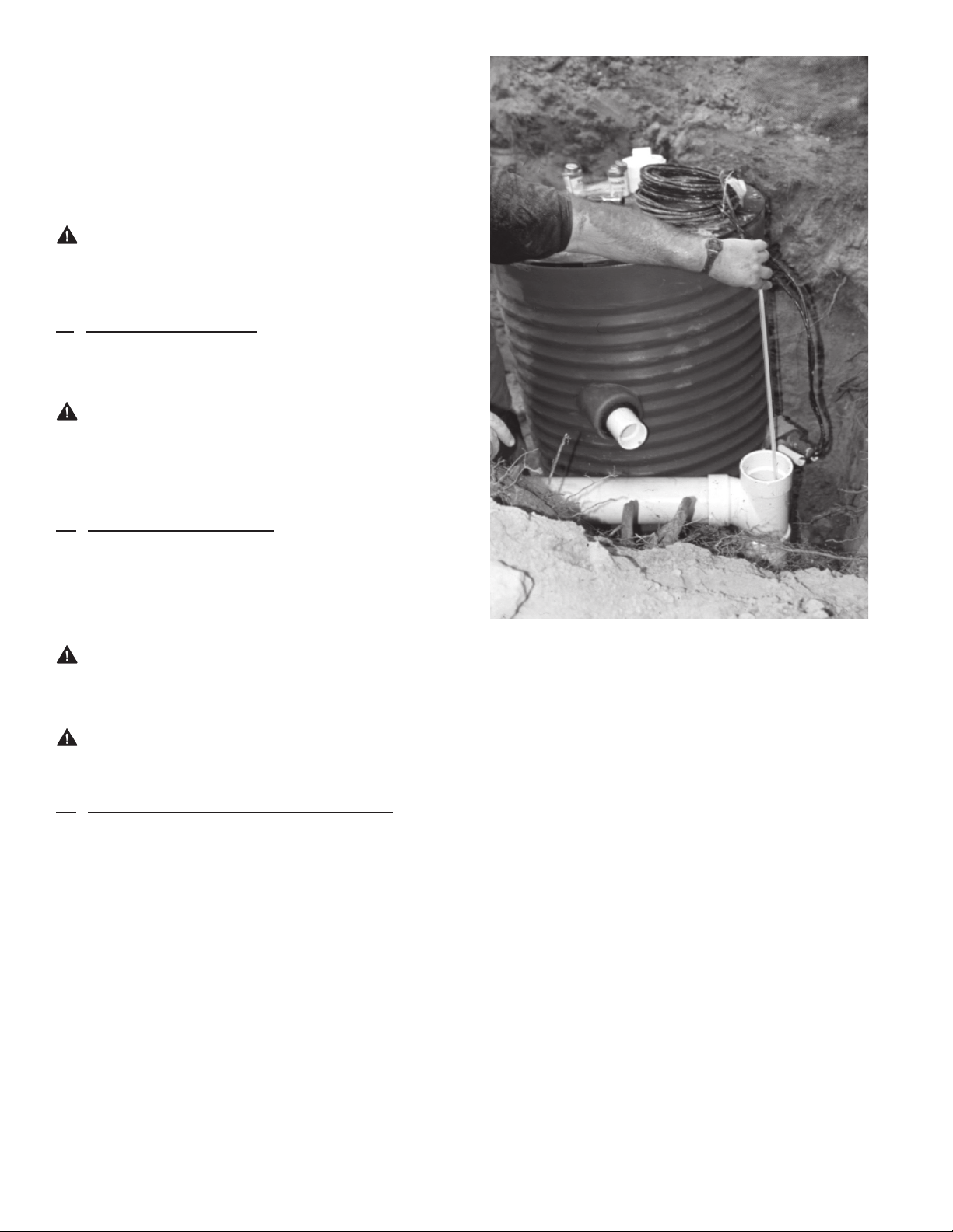
4.5 Joining Pipe and Fittings
Immediately following application of solvent cement and before
it starts to set, push the pipe into the fitting socket with a 1/4-turn
twisting motion to evenly distribute the solvent cement within
the joint. A full bead of solvent cement should form around the
circumference of the joint. Hold the joint together for approximately
30 seconds to make sure that the joint does not move or come apart.
NOTICE The absence of bead formation or the presence
of voids or gaps in the bead areas is a sign of insucient solvent
cement application. If this is observed, immediately pull the joint
apart and reapply an adequate amount of solvent cement.
4.6 Cleaning Joint
Using a clean cloth, wipe all excess solvent cement from the exterior
of the pipe and fitting.
4.7 Joint Curing
The joint must not be moved or handled for a minimum of two
minutes, after which the joint must be carefully handled until the
solvent cement has gone through the proper set time based on
ambient temperature. Suggested set times are:
• Ambient Temperature 60 to 100 °F (15 to 40 °C), 1/2 hour set time
• Ambient Temperature 40 to 59 °F (5 to 14 °C), 1 hour set time
• Ambient Temperature 20 to 39 °F (–5 to 4 °C), 2 hour set time
• Ambient Temperature 10 to 19 °F (–12 to –6 °C), 4 hour set time
NOTICE The joint must be adequately set prior to
use. Required set time depends on site temperature. The above
information is based on the guidelines of ASTM D2855, “Standard
Practice for Making Solvent-Cemented Joints with Poly Vinyl Chloride
(PVC) Pipe and Fittings.” It is the installer’s responsibility to determine
that the joint has properly set for handling, testing and use.