7.2.3 Shortening pipes
7.2.4 Shaft connections to AquaTracControl
7.2.5 Embedding and backfilling of pipes and shafts
The provisions of DIN EN 1610 and
DWA-A 139 generally apply. Carry out
backfilling according to design specifica-
tions. It includes side filling, covering
within the embedding area, and main
backfilling. Create the embedding of the
pipe in the embedding area with stone-
less, compactable material. Backfill the
bedding material evenly on both sides of
the pipe above the pipe crown in layers
of approx. 15cm, and compact using
light compaction equipment only or,
if required, even by hand. Further filling
(as of approx. 15cm above the pipe
crown) must be made in layers with con-
stant compaction of the filling material.
Mechanical compaction of main backfill-
ing with light to medium equipment
directly above the pipe should only be
performed starting from a minimum
Cut the pipes to length in the middle of
the corrugation trough and align upright
to the pipe axis using a fine-toothed saw
or other appropriate tools. Remove
edges and irregularities on the cutting
surfaces with a grater, file or another
suitable tool.
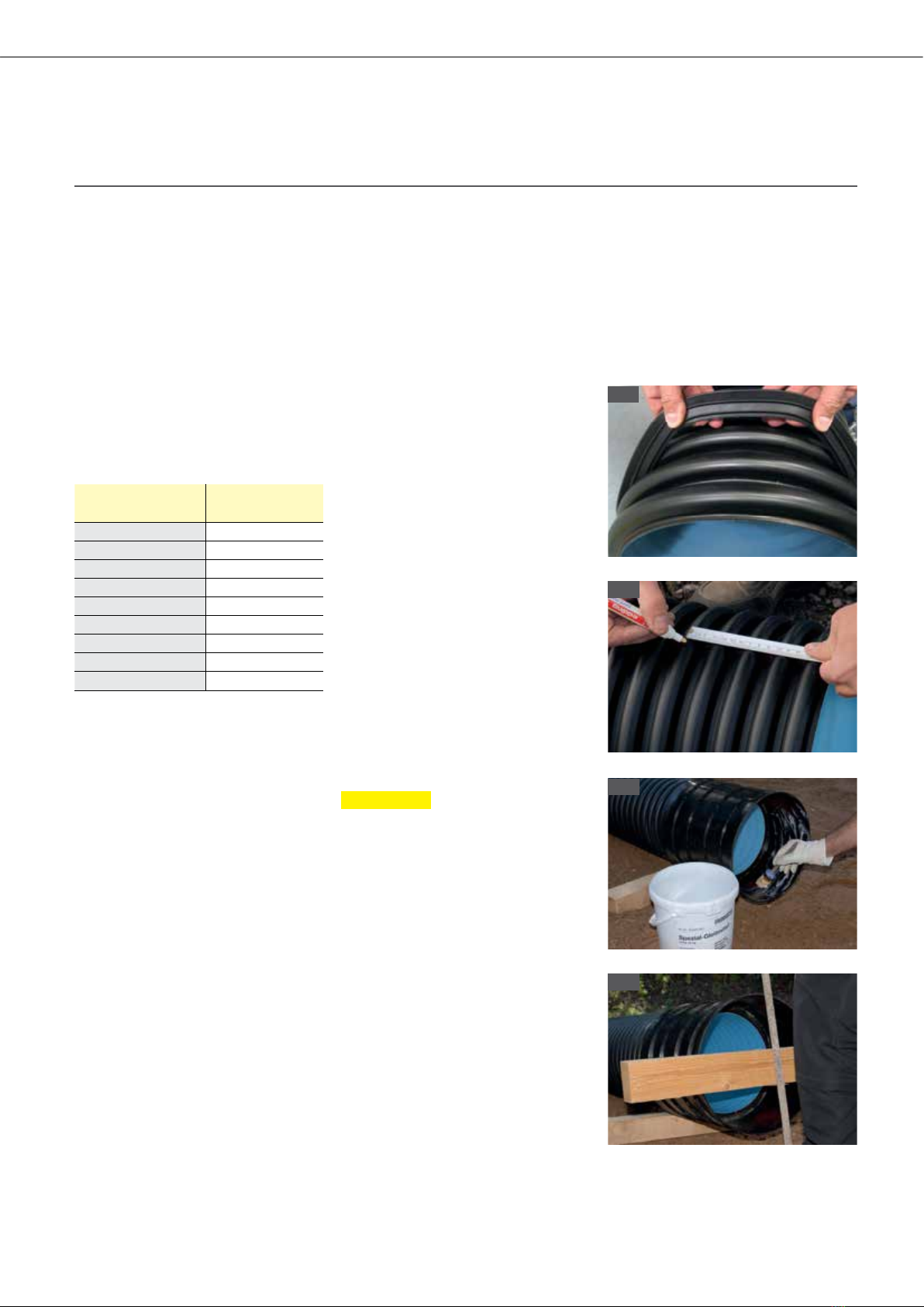
Proceed as follows:
1. Clean the insertion area of the pipe
and the insides of the shaft connec-
tions at AquaTracControl from dirt
using a rag or similar.
2. Insert the profile sealing ring continu-
ously and without overexpanding indi-
vidual spots into the first complete
corrugation trough of the AquaPipe
pipe at the spigot (when cutting pipes,
make sure that cuts are in the middle
of the corrugation trough and there is
no damage to the corrugation edge).
3. Evenly apply a sucient amount of
lubricant to the profile sealing ring
and the inside of the shaft connec-
tion. Do not use oils and greases.
4. Right before installation, check the
shaft connection and pipe ends
again for foreign objects and remove
if necessary. Please pay particular
attention to gravel, sand or crushed
stones which could have entered the
insertion area during work at the pipe
and shaft and/or stick to lubricated
sections.
5. Insert pipes to the limit stop. Protect
the pipe section using a square timber
and distribute installation forces
equally during installation.
Please observe the following
The use of heavy construction gear
and vehicles and storing excavated
material in the area over covered
pipes are not admissible unless
relevant load conditions have been
considered in the static calculation.
This holds true particularly for pipe
systems with low depths of cover.
7.2.6 Placing the extension pipe
The extension pipe must be inserted into
the upper area of the shaft base body.
For watertight systems, place the profile
7 Installation
thickness of 30cm above the pipe
crown. Use heavy compaction equip-
ment only starting from a depth of cover
of 1.0m above the pipe crown. Choose
compaction equipment, the number of
compaction runs and the thickness of
layers subject to compaction depending
on the material to be compacted and the
pipe system to be installed. To avoid
load concentration on the pipe, consist-
ent compaction throughout the entire
embedding area must be ensured. In
addition, the pipes must not come in
contact with compaction equipment.
Preferably secure the pipes from lateral
and vertical forces during installation.
Embed the shaft and compact the
bedding material analogously to the
pipe. Insert the extension pipe for this
process (see Section 7.2.6).
sealing ring into the first corrugation
trough of the extension pipe. Evenly
apply a sucient amount of lubricant to
the profile sealing ring and the inside
of the insertion area. Do not use oils
and greases. Afterwards, insert the
IM AquaPipe
6