Fracarro 3DG-2S2-2T User manual

3DG-2S2-2T
Operating instructions

2
English
• Theproductcanonlybeinstalledbyqualiedpersonnelincompliancewithlocalsafety
lawsandregulations.FracarroRadioindustrieisfreefromallcivilandcriminalresponsibility
duetobreachesofthecurrentlegislationderivedfromtheimproperuseoftheproductby
theinstaller,userorthirdparties.
• Theproduct must beused infull compliancewith theinstructions givenin thismanual,
in order to protect the operator against all possible injury and the product from being
damaged.
Installation warnings
• Theproductmustnotbeexposedtowaterdripsandmustbeinstalledindoorsinsidein
dryplaces.
• Dampandcondensationdropscoulddamagetheproduct.Consequentlyalwayswaitfor
theproducttobeperfectlydrybeforeuse.
• Donotinstalltheproductaboveorclosetosourcesofheat,industyatmospheresorwhen
itcouldbeexposedtocorrosivesubstances.
• Hightemperaturesoroverheatingcouldcompromisetheproductfunctionsandlife.
• Handlewithcare.Knockscoulddamagetheproduct.
• Leaveplentyofspacearoundtheproducttoensuresufcientventilation.
• Ifyouwall-mounttheproduct,useexpansionanchorsthataresuitableforthecharacteristics
ofthesupportbracket.
Earthing the antenna
• Theproductmustbeconnectedtotheantennalineearthelectrodeincompliancewiththe
EN60728-11standard.
• Theearthscrewisindicatedwiththesymbol
• ItisimportanttoobservethedispositionsoftheEN60728-11standardandnotconnectthis
screw(terminal)(product)tothepowersupplyearthline.
IMPORTANT
• Never remove the product cover: dangerous powered components could be accessible
whenthecasingisopened.
• Incaseofamalfunction,donotattempttorepairtheproductbecausethiswouldinvalidate
theguarantee.
1. SAFETY WARNINGS

3
English
Operating instructions
The 3DGex unit has a cabinet for housing up to a maximum of 6
differenttypesofmoduleandacontrolunitthathasvariousfunctions.
Thecontrolunitintherstslotenables:
• Poweringupto6cards
• Programmingtheunitusingthekeypadandon-boarddisplay.
• Programmingtheentirecentralstationlocallyorremotelyusingthe
LANportandthewebinterface
• Monitoring the central station locally or remotely using the LAN
port, and to receive the signals via email in case of problems
(CONTROLLERHOSTincluded)
• Importingandexportingcongurationstoandfromotherstationsof
thesametypebymeansoftheUSBportorthePCmemory
• Visuallycheckingthestationstatus,bymeansofthetwosignalleds
Thecabinetdoesnotjustphysicallyhousethemodulesbutalso:
• Enablestransferringthecorrectvoltagetothemodules.
• Enablescommunicationsbetweenthemodulesandcontrolunitfor
programmingandremotemonitoring.
• Enablescarryingforwardthetunedinsignalsfromothermodules,
usingitasanadditionalinputonthebackpanel.
• MixestheoutgoingRFsignalsandampliesthem.
ThecabinetalsoprotectstheaccesstotheconnectionsandCAMS,
owingtoadoorwithlockandkeyandaprotectiveshellfortheCAMs.
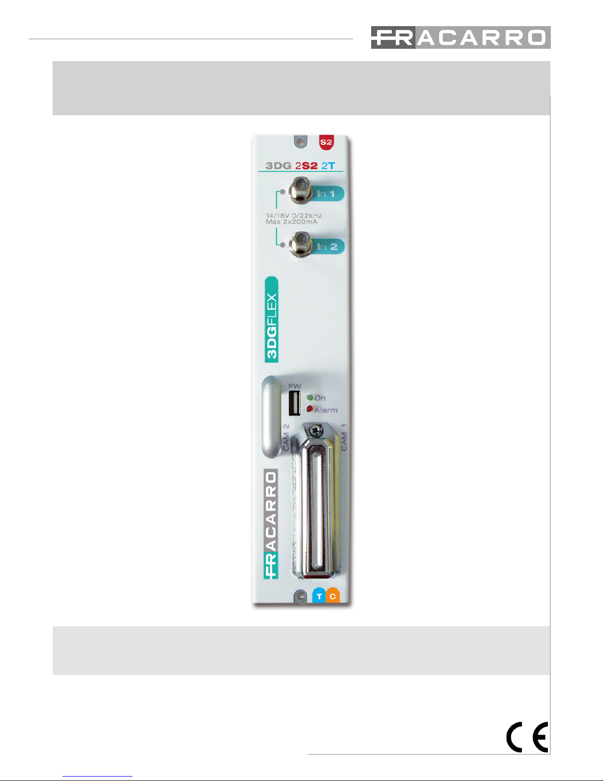
The 3DG-2T2-2T module can be housed in the 3DGFlex unit, and
enablescreating2channelsinDVB-TorDVB-Cstandard,beginning
fromthestreamof1,2or3satellitetransponders(QPSK-DVB-S2).
Infact,2DVB-TorDVB-Cmuxescanbecreatedusingassourcesthe
contentsof2differentsatellitetransponders,comingfrom2inputs,
andathirdsatellitetransponderwiththetrasportstreamthoughthe
backpanelcominginasinputfromapreviousmodule.
Themodulatorisfullband,thereforethe2muxescanbemodulatedon2VHF-UHFband
channels.
Eachmodule has2 satelliteinputs (SAT 1e SAT 2)and adouble commoninterface slot
associated to each of the 2 inputs, which enables decrypting programs from the same
transportstream.
ThereisalsoaUSBportforrapidlyupdatingthermwaredirectlyfromtheUSBdrive,and
forcopyingthemodulecongurationparameterstoorfromthedriveusingthecontrolunit
USBport.
Itcanbeprogrammedinoneoftwoways:Basicmoduleprogrammingusingthekeypadand
LCDdisplayonthestationcontrolunit;completeprogrammingusingthewebinterfacewith
alocalorremotePCconnectedtotheLANportonthecontrolunit.
Each3DG-2S2-2Tcangenerate14/18Vperinput,22KHztoneandDISEqC1.0tone-burst
tocontrolothermultiswitches,ifany,orLNBandisequippedwithashort-circuitprotection
device.Max.remotepowermaximumcurrent200mA@14V/18Vperinput.
2. PRODUCT DESCRIPTION
Importingandexportingcongurationstoandfromotherstationsof

4
English
CAMinsertion ToremovetheCAM,press
thecorrespondingbutton
3. PRODUCT INSTALLATION
3.1 PACKAGING CONTENTS
All’internodell’imballosonocontenutiiseguentimateriali:
• modulo3DG
• avvertenzeperlasicurezzael’installazionedelprodotto
3.2 MODULE ASSEMBLY
3.3 INSERTION AND REMOVAL OF THE CAM MODULES
Seethegures:

5
English
Operating instructions
1.Insertthemoduleintotheheadend(theheadendmustbeoff).
2.SwitchtheheadendON;waitfortheheadendinitialization(theFracarrologoisdisplayed)
3.Connecttheantennacablestotherelevantinputs
4.PresstheVkeyandenterthemenu;entertheuser’scode(1234bydefault)andpressVagain.
Nowtheheadendwill scan andndthe presentmodules.Nowyoucan programtheunitas
speciedfromthepage7.
5.Checktheoutputsignalattheoutputconnectoroftheheadendwithaeldmeter
6.ConnectthedistributioncabletotheTVoutputconnector.
Inalternativaalpunto4èpossibileutilizzareunPCperaccedereallaprogrammazionedelmo-
dulotramiteinterfacciaweb.
Alternativelytoitem4,youcanuseaPCtoprogramthemodulebywebinterface.
Themodulecanberesettodefaultparameters(seethecontrolunit’sinstructions).ATTEN-
TION:thedefaultlanguageisEnglish.
Afterresetting,youcansettheparametersagainasdefaultparametersmightnotmeetyour
needs.
The3DG-2S2-2TunitisequippedwithtwofrontLEDs(redandgreen)whichindicatethemo-
dulestatus(i.e.ON,underalarm,underlockage,underbootingorprogramming).
Thefollowingtablehelpsunderstandtheluminoussignalizations.
LED STATUS – START UP
GREEN LED RED LED MEANING
ON ON Systemstartup
FLASHING OFF Applicationstartup
ON OFF Systemready
LED STATUS – SYSTEM READY
GREEN LED MEANING
ON Normaloperation
FLASHING Systemcommunicatingviaweborkeyboard
RED LED MEANING
OFF Normaloperation
ON Faultand/oroverow
FLASHING Inputenabledwithoutsignal
BOOTING STATUS
GREEN LED RED LED MEANING
OFF Flashing Updatingand/orrecoveryphase
4. INSTRUCTIONS FOR USE

6
English
5. PROGRAMMING INSTRUCTIONS
NB:TheControlunittimeoutis5minutes:afterthattime,ifnootherchangesaremade,the
controlunitreinstatesthelastsavedmoduleconguration.
5.1 BASE PROGRAMMING FROM THE STATION
The 3DG-2S2-2T module can be programmed using the keyboard on the station control
unit.
To access the programming menu, press √ and input the user code (default is 1234). To
changethe3DG-2S2-2Tlanguageenterthemainmenuinthecontrolunit“LANGUAGE”,
andselecttherequiredlanguagepressing√.
Foralltheprogrammingactivitiesandtounderstandtheprogrammingmenusgiveninthe
followingowcharts,refertothekeygivenbelow:
KEYBOARD KEY FUNCTION
or Forconrminganenteredvalueorenteringthemenu/submenu
or Fordeletinganenteredvalueorexitingthemenu
Fornavigatingamongthevariousitemsofthemenu
Forchangingtheparameters
Forenteringthevalues
Forsavingthechanges
S
...... 9
WXYZ
0
➤
➤
➤
➤
✗
➤
✓➤
➤
➤

7
English
Operating instructions

8
English
Key:
■ OnlyformodulecongurationinDVB-T
■OnlyformodulecongurationinDVB-C

9
English
Operating instructions
Key:
■ OnlyformodulecongurationinDVB-T
■OnlyformodulecongurationinDVB-C

10
English
INPUT
Set frequency (SAT 1):
DiSEqC:allowssettingtheDiSEqCaccordingtothesatellite(A,B,CoD).
FREQ.(MHz):allowssettingtheextendedfrequencyforthetranspondertobereceived.
POLARITY:tosethorizontalorverticalpolarity.
TYPELNB:tosetthetypeofLNB.
SYMBOLRATE:allowssettingthesymbolrateforthetranspondertobereceived.
Set IF frequency (SAT 1):
DiSEqC:allowssettingtheDiSEqCaccordingtothesatellite(A,B,CoD)
FREQ.IF(MHz):allowssettingtheIFfrequencyforthetranspondertobereceived.
LNB:tosetthetypeofLNB.
SYMBOLRATE:allowssettingthesymbolrateforthetranspondertobereceived.
Measures (SAT 1)
Lock:tocheckwhetherthereceiverhaslockedthesignalornot.
Networkname:-readingonly–tocheckthetranspondername.
BER:toviewtheBER(quality)oftheinputsignal.
SNR:toviewthesignal/interferenceratiooftheinputsignal.
Common Interface (SAT 1)
Modulename:toverifythecommoninterfacemodulename.
Enabledprograms:toaddorremovetheprogramstobedecrypted.
ResetCAM:toresettheCAM
SAT 2= see SAT 1
BACK PANEL
Enable:
OFF:deactivatestheTPinputsignalfromthebackpanel
ON:enablestheTPinputsignalfromthebackpanel
OUTPUT
(mux 1)
Configuration:
Output frequency:
Bandwidth(onlyformodulessetinDVB-T):tosettheoutputchannelbandwidth
fromtheavailableones(6,7,8MHz)
Frequency(MHz):tosettheinputchannelfrequency
Output channel:
Country:tosettheinstallationcountrychannels.
Outputchannel:tosettheoutputchannel.

11
English
Operating instructions
All PIDS:afunctionthatallowsenablingordeactivatingtheoutputbroadcastofall
theprograms.
(PID)containedintheselectedinput(inothercases,themaximumlimitis64programs).
OFF:functiondeactivated
SAT1:selectedinputSAT1
SAT2:selectedinputSAT2
INPUTBP:selectedinputbackpanel
FEC (only for modules set in DVB-T):tosettheFEC(ForwardErrorCorrection)
parameterfromtheavailableones(1/2,2/3,3/4,5/6,7/8)
Guard interval (only for modules set in DVB-T):
tosettheguardintervalfromtheavailableones(1/4,1/8,1/16,1/32)
No. Of carriers (only for modules set in DVB-T):
tosetthenumberofcarriersbetween2Kand8K.
Constellation:tosettheconstellationusedtomodulatethecarriersasQPSK,
16QAMand64QAMforDVB-Tand16QAM,32QAM,64QAM,128QAMand256QAM
forDVB-C.
RF level:tosettheoutputlevelonascalebetween0and15,whereonestepequals
1dB.IfitissetonOFFtheoutputsignalisdeactivated.
Spectrum:toregulatethespectrumasNORMALorINVERTED,accordingtothe
receptioninstrument,thatcouldonlyfunctionwithoneofthetwomodes.
Normally“NORMALSPECTRUM”isused”.
Bitrate: to know the measures made on the multiplex bitrate in the output programs. In
particular,thefollowingcanbedisplayed:
Bitrate used:showsthebitratesused.Thisparameterreferstoatotalmeasureof
alltheprogramsaddedtothelistofoutputprograms,expressedinkbit/s.
Bitrate available:showsthebitratesavailable.Thisparameterreferstothetotal
availableoutputbitratesafterincludingoneormoreprograms,andisexpressedin
kbit/s.
Peak bitrate used: ameasureinbit/softhemaximumbitratepeakusedbythe
programsintheoutputmultiplex.
Peak bitrate available:ameasureinbit/softhetotalavailablebitratepeaksavailable
intheoutputmultiplex.
Reset bitrate peak: toresetthepeakstotheinitiallevels,calculatedaccordingtothe
COFDMmodulationsettings.Afterabitrateoverow,whenthepeakshavereachedtheir
limit,thisfunctionhastobeused.

12
English
Overflow alarm:bitrateoverowalarmmanagement.
Alarm state:showsifabitrateoverowhasoccurred
Cancel alarm:tocanceltheoverowalarm.Theproductisresetonthestandard
workingconditions(theredLEDisturnedoff)
Enable:toenable(ON)ordeactivate(OFF)theoverowalarmsignalfunction
(mux 2) see mux 1
Back panel:torespectively:deactivatetheoutputsignalpassageonthebackpanel
(OFF),toenablethesatelliteoutput1signalpassageonthebackpanel(SAT1),toenable
thesatelliteoutput2signalpassageonthebackpanel(SAT1),toenablethereceived
inputsignalpassageonthebackpanelfromthemodulethatwaspreviouslysetonoutput
onthebackpaneltothesubsequentmodule(InputBP).
PROGRAMS
(mux 1)
Add all prog:totransfertheinputprogramlistintheoutputmuxaccordingtothe
selectedinput(backpanel,SAT1orSAT2)avoidingtheneedtomanuallyaddthemone
atatime.
List order: tosettheordercriteriafortheprogramlists.
INPUT:orderedbyclassicationtotheinputnumber(SAT1,SAT2,BP)
LCN:orderedbyLCN,i.e.accordingtothenumberassociatedtotheprogramno
matterwhatinputitcomesfrom.
PRIORITY:orderedbypriority,i.e.accordingtothepriorityassignedtotheprogram.
Channel list:tosetthelistofoutputprograms.
• Add:toaddtheselectedprogramtothelistofoutputprograms,whenithasbeenadded
theprogramismarkedwithan(A)infrontofitsnameinthechannellist.
• Remove: toremovetheselectedprogramfromthelistofoutputprograms.
• Decrypt yes/no:toenableordeactivateprogramdecryption.Oncetheprogramhasbeen
enabledfordecryption,itismarkedwithan(*)infrontofitsnameinthechannellist.
Iftheprogramisaddedanddecrypted,itismarkedwithan(A*)infrontofitsnameinthe
channellist.
• Priority:tosetthepositionofeachprogram,theonewiththehighestpositionnumberwill
bethersttobecutifthereisanoverow.
• SetLCN:toset the programLCN.Theavailablevalues arebetween0and999. 1000
meansadeactivatedLCN.
• Band:managetheprogrambitratemonitoring

13
English
Operating instructions
-Monitoryes/no:toenable/deactivatetheprogrambitratemonitoringifithasnotbeen
addedtothechannellist.Thisenablesverifyingwhethertheprogramhasbeenincludedin
theoutputmuxornot,accordingtotheprogrambitrate.
-Averagevalue:toviewtheprogramaveragebitratevalue
-Peakvalue:toviewtheprogrampeakbitratevalue.
• Channelproperties:toviewusefuldataabouttheprograms.
-Programname:toviewtheprogramname.
-Providername:toviewtheprovidername.
-Input:toviewthecorrespondinginputprovenance.
-Programtype:toviewtheprogramtype(TV,RADIO…)
-ServiceID:toviewtheprogramserviceID
• Advanced configurations:
Select country:toselecttheinstallationcountry.
TSID:toviewandchangetheIDassociatedtothetransportstreambythebroadcaster.
The 2 parameters above are important for the LCN to function correctly, and must be input
consistent with the same parameters input in the connected decoders and televisions.
(mux 2) see mux 1
MEASURES
• Serialnumber:toviewthemoduleserialnumber.
• SWrelease:toviewthemodulesoftwarerelease.
• SWupdate:toupgradethemodulefromtheUSBdrive.
-SWupdateoutcome:toviewtheoutcomeofthesoftwareupdate.
-StartSWupdate:torunthesoftwareupdatefromtheUSBdrive.
• DVB-T->DVB-C(DVB-C->DVB-T)tosetthemodulationstandardonoutputfromthe
module,fromDVB-TcurrentsettoDVB-C(fromDVB-CcurrentsettoDVB-T)

14
English
5.2 PROGRAMMING BY WEB INTERFACE
Afterthepreliminaryprogrammingusingthestationkeypad,theadvancedprogrammingcanbe
doneusingtheincorporatedWEBMANAGEMENTinterface.
Itisimportantnottocongurethe6modulesusing6differentbrowsingcardsatthesametime,
asthecontrolunitdoesnotrespondtoamultiplerequestforwebparameters.
Furthermore,twodifferentoutputscannotbeconguredinthesamemoduleontwodifferent
browser cards, otherwise errors will be generated. Errors also occur when the inputs are
conguredinthesameway.Thisproblemalwaysariseswhenoneormorecardsareopenedon
thesamebrowserwheretheparameterscanbeset;theonlyonethatwillcontinuetofunction
isthelastonethatwasopened,
IMPORTANT:toaccessprogrammingfromthewebinterface,thecontrolunitmustbeoutside
themainmenu(logo3DGexFracarroshownonthedisplay).
NOTE: the web interface could vary according to the firmware release installed in the
module.
Proceedasfollows:
1.ConnectthePCtothemoduleusingaRJ-45CAT-5Ecrosslead.
2. In the 3DGex control unit change the IP address, setting one that belongs to the same
subnetastheonesetinthePClocalnetworkcardproperties.
Forexample:
a.ParameterssetinthePCnetworkcardproperties:
IP:192.168.0.3
SUBNETMASK:255.255.255.0
GATEWAY:192.168.0.1
b.Parameterstosetinthecontrolunit
IP:192.168.0.2
SUBNETMASK:255.255.255.0
GATEWAY:192.168.0.1
3.Startthewebbrowser(recommended:GoogleChrome,Mozilla)
4.IntheaddressbartypeintheIPaddressassociatedtothe3DGex;
thefollowingHOMEPAGEopens:

15
English
Operating instructions
5.2 PROGRAMMING BY WEB INTERFACE
Afterthepreliminaryprogrammingusingthestationkeypad,theadvancedprogrammingcanbe
doneusingtheincorporatedWEBMANAGEMENTinterface.
Itisimportantnottocongurethe6modulesusing6differentbrowsingcardsatthesametime,
asthecontrolunitdoesnotrespondtoamultiplerequestforwebparameters.
Furthermore,twodifferentoutputscannotbeconguredinthesamemoduleontwodifferent
browser cards, otherwise errors will be generated. Errors also occur when the inputs are
conguredinthesameway.Thisproblemalwaysariseswhenoneormorecardsareopenedon
thesamebrowserwheretheparameterscanbeset;theonlyonethatwillcontinuetofunction
isthelastonethatwasopened,
IMPORTANT:toaccessprogrammingfromthewebinterface,thecontrolunitmustbeoutside
themainmenu(logo3DGexFracarroshownonthedisplay).
NOTE: the web interface could vary according to the firmware release installed in the
module.
Proceedasfollows:
1.ConnectthePCtothemoduleusingaRJ-45CAT-5Ecrosslead.
2. In the 3DGex control unit change the IP address, setting one that belongs to the same
subnetastheonesetinthePClocalnetworkcardproperties.
Forexample:
a.ParameterssetinthePCnetworkcardproperties:
IP:192.168.0.3
SUBNETMASK:255.255.255.0
GATEWAY:192.168.0.1
b.Parameterstosetinthecontrolunit
IP:192.168.0.2
SUBNETMASK:255.255.255.0
GATEWAY:192.168.0.1
3.Startthewebbrowser(recommended:GoogleChrome,Mozilla)
4.IntheaddressbartypeintheIPaddressassociatedtothe3DGex;
thefollowingHOMEPAGEopens:
NOTE:toaccessthewebinterface,theloginmustbeauthenticatedjustoncebyenteringthe
usernameanddefaultpassword.
Username:admin
Password:1234
First of all, select the language for the web interface menus (English, Italian, French and
German).
Thegeneralstatusofthe3DGexstationcanbeviewed.
The rst module to be present is always the 3DG-CU control unit (refer to the control unit
manual to set its parameters, including the network parameters), the other modules from
position1to6mayormaynotbepresent< >.
Iftheyarepresent,thisscreenshowsthemodulestatus.
The3DG-2S2-2Tmodulespecicallyshows:thesymbolV,iftheenabledinputshaveasignal
andthereceiverhaslockedit,thesymbol<
The3DG-2S2-2Tmodulespecicallyshows:thesymbolV,iftheenabledinputshaveasignal
>ifatleastoneoftheenabledinputsdoesnot
haveasignaland/orthereceiverhasnotlockedit.
Thesymbol<
haveasignaland/orthereceiverhasnotlockedit.
>isalsodisplayedifthereisabitrateoverow
Againsteachinput(SAT1,SAT2andInputBackPanel)forthepresentmodules,thereisalso
acoloureddot:
-Greeniftheinputisenabledandthereceiverhaslockedasignal
-Rediftheinputisenabledandthereceiverhasnotlockedasignal
-Greyiftheinputisdeactivated
• Greenfornormalfunctioningconditions
• Redifthereisabitrateoverow
• Greyiftheoverowfunctionisdeactivated

16
English
For the enablement or otherwise of the output back panel, the wording “Output BP ON” or
“OutputBPOFF”isshown.
By clicking with the mouse on one of the present modules, the screen below opens, which
showsfurtherdetailsaboutthestatusoftheselectedmodule:
Beginningfromthetop,thesoftwarereleaseandthemoduleserialnumberareshown.
Thencertainparametersareshownaboutthesignallevelandqualitytotheinputs(BER,SNR),
offsetwhichisthefrequencycorrectionperformedbythecontrolunitwhenthetransponderis
lockedand,nally,thenameofthelockedmultiplexer.
Fortheoutput,indicationsaregivenabouttheuseoftheavailablebandforeachmux.
In detail: bitrate used and available in numeric form (MBps), relative peaks and graphic bar
showing the real time and memory of maximum peak bitrate used and available, again in
numericandgraphicformat.
Thesectionsforthe2muxesshow2“buttons”toresetthepeakbitratememoryandthebitrate
overowalarmsignalledwithareddot.
Rememberthat,asdescribedabove,thedotindicatestheoverowstateifitisenabled,notthe
statusofthemux,whichisshowninthecontrolunitstatuspage.
Clickonthemousetoselectoneofthe2inputs,andthefollowingscreenopens:

17
English
Operating instructions
Thereceiverinputparameterscanbeset.
First of all, the input can be enabled or deactivated by agging “enable” or otherwise,
consequentlyfromthedropdownmenuselectwhethertosetthefrequencyortheIFfrequency.
SelectingDiSEqCenablessettingtheDiSEqCaccordingtothesatellite(A,B,CorD).
Aspecicsectionenableswritingtheextendedfrequencyorin1IFofthetranspondertobe
received.
Accordingtotheselectedfrequencyforthesetting,thecorrespondingpolaritycanbeselected.
Thelastitemisusedtosetthesymbolratewritingtheextendedrateinaspecicsection.
NB:forthechangestobeeffective,clickon“Save”.
Therightsectioncontainsadditionaldetailedinformationwithrespecttothepreviousmenus,
aboutthelockedtransponder,including:Lock,BER,SNR,Offset,NetworkID,Originalnetwork
IDeTransportstreamID.
Clickwiththemouseon“CommonInterface”toopenthefollowingscreen:

18
English
BesidesindicationsastowhethertheCAMmoduleispresentornot,thereisatablewithalist
oftheprogramsinthetransponderlockedtotherelativeinput.
Besidestheprogramname,wecanseeiftheprogramisfreetoair< >orencrypted< >
andinthiscasewecanhavetheprogramdecryptedbytheCAMbyaggingthebox.
Therearekeysbelowtheprogramtableto:resettheCAM,accessthecommoninterfacemenu,
displaytheCAMmessagesandsettheadvancedCAMmodulefunctions.
Thelast2arenotalwaysenabled,butcanbeenabledrespectively.WhenaCAMisinputand
whentheCAMsendsamessage,byclickingon“ShowCAMmessages”theycanberead.
NB:forthechangestobecomeeffectiveclickon“Save”.

19
English
Operating instructions
Thefollowingscreenopensbyclickingon“Commoninterfacemenu”:
InformationisgivenabouttheCAMmodule,theSmartcardandthelastCAMsoftwarerelease
canalsobedownloaded.ThemenuabovereferstotheinputCAMandinthiscasethemenu
headingsrefertothatspecictypeofCAM.ClickonAdvancedSettingstoviewthefollowing
screen,wheretheCAMmoduleadvancedfunctionscanbeset:
Therst2itemsCAPMTManagementandCAPMTSendingenablechangingtheCAMdecrypt
management, by choosing from the
methodsinthedropdownmenu;ifthe
thirdoptionCAPMTResizeisenabled
byaggingthebox,theCAMissetfor
decryptingonlytheaudioandvideoof
theselectedprogramsinthecommon
interfacecard(inthiscasetherecould
beagreaternumberofprogramsthat
canbedecrypted).Ifitisdeactivated,
everythingisdecrypted:audio,video,
ttx,subtitles,MHP,etc.
The CAPMT Resize Attempts
parameter is the maximum number
of attempts to send the CAM
congurationbeforeitisresetifthere
isamalfunction.
In the status menu, click with the
mouse on the input back panel to
accessthefollowingscreen:

20
English
Inthissectiontheinputcanbeenabledforthebackpanelsignalinthemodulecomingfrom
theoutputbackpanelofthemoduleinthepreviousposition.
Therighthandsectionalsodisplayscertaininformationabouttheinputsignal,including:ifitis
lockedornot,thenetworkname,networkID,originalnetworkIDandthetransportstreamID.
Inthestatusmenuagainclickwiththemouseononeofthe2outputmuxestoopenthe
followingscreens:
Standard DVB-T
Table of contents
Other Fracarro Control Unit manuals
Popular Control Unit manuals by other brands

Atex
Atex CONEX user manual

Sentiotec
Sentiotec Pro C3 Instructions for installation and use

GE
GE WH18X28174 Part Install Instructions

FLOWROX
FLOWROX PV 80 Installation, operation and maintenance instructions

MAZATROL
MAZATROL M PLUS Series Maintenance manual

Governors America
Governors America SYC6714 manual

Redi Controls
Redi Controls RuptureSeal RS-2 operation & maintenance

Surface Concept
Surface Concept HVPS-HC manual

KIESELMANN
KIESELMANN 5093 Series Operating instruction

Carel
Carel Ultracap instructions

OMAL S.p.A
OMAL S.p.A 424 Series Maintenance and spare parts

SMC Networks
SMC Networks S0700 Installation and maintenance manual