Fracarro D-MATRIX 4S-FTA User manual

Guida rapida - Quick guide
Guide rapide - Kurzanleitung
D-MATRIX 4S-FTA code 283135

2
AVVERTENZE PER LA SICUREZZA
L’installazione del prodotto deve essere eseguita da personale qualificato in conformità alle leggi e normative locali
sulla sicurezza. Fracarro Radioindustrie di conseguenza è esonerata da qualsivoglia responsabilità civile o penale
conseguente a violazioni delle norme giuridiche vigenti in materia e derivanti dall’uso del prodotto da parte
dell’installatore, dell’utilizzatore o di terzi. L'installazione del prodotto deve essere eseguita secondo le indicazioni di
installazione fornite, al fine di preservare l'operatore da eventuali incidenti e il prodotto da eventuali danneggiamenti.
Non aprire il contenitore del prodotto, parti a tensione pericolosa possono risultare accessibili all'apertura dell'involucro.
Avvertenze per l’installazione
●Il prodotto non deve essere esposto a gocciolamento o a spruzzi d’acqua e va pertanto installato in un
ambiente asciutto, all’interno di edifici.
●Umidità e gocce di condensa potrebbero danneggiare il prodotto. In caso di condensa, prima di utilizzare il
prodotto, attendere che sia completamente asciutto.
●Maneggiare con cura. Urti impropri potrebbero danneggiare il prodotto.
●Lasciare spazio attorno al prodotto per garantire una ventilazione sufficiente.
●L’eccessiva temperatura di lavoro e/o un eccessivo riscaldamento possono compromettere il funzionamento
e la durata del prodotto.
●Non installare il prodotto sopra o vicino a fonti di calore o in luoghi polverosi o dove potrebbe venire a
contatto con sostanze corrosive.
●In caso di montaggio a muro utilizzare tasselli ad espansione adeguati alle caratteristiche del supporto di
fissaggio.
La parete ed il sistema di fissaggio devono essere in grado di sostenere almeno 4 volte il peso
dell’apparecchiatura.
●Attenzione: per evitare di ferirsi, questo apparecchio deve essere assicurato alla parete/pavimento secondo le
istruzioni di installazione.
●Per “APPARECCHIATURE INSTALLATE PERMANENTEMENTE”, un dispositivo di sezionamento facilmente
accessibile deve essere incorporato all’esterno dell’apparecchiatura; per “APPARECCHIATURE CON SPINA DI
CORRENTE”, la presa deve essere installata vicino all’apparecchiatura ed essere facilmente accessibile.
●Il prodotto deve essere collegato all’elettrodo di terra dell’impianto d’antenna conformemente alla norma EN
60728-11.
La vite predisposta per tale scopo è contrassegnata con il simbolo
●Si raccomanda di attenersi alle disposizioni della norma EN 60728-11 e di non collegare tale vite alla terra di
protezione della rete elettrica di alimentazione.
Simbolo di terra dell’impianto d’antenna
Simbolo classe II con una connessione alla terra funzionale
Per le SPECIFICHE TECNICHE, riferirsi al MANUALE INSTALLATORE scaricabile dal sito
FRACARRO.IT alla pagina del prodotto
Avvertenze generali
In caso di guasto non tentate di riparare il prodotto altrimenti la garanzia non sarà più valida.
Le informazioni riportate in questo manuale sono state compilate con cura, tuttavia Fracarro Radioindustrie
S.r.l. si riserva il diritto di apportare in ogni momento e senza preavviso, miglioramenti e/o modifiche ai
prodotti descritti nel presente manuale. Consultare il sito www.fracarro.com per le condizioni di assistenza
e garanzia.

Italiano
3
DESCRIZIONE DEL PRODOTTO
D-MATRIX-4S FTA è un apparato che permette di generare due coppie di multiplex adiacenti modulati
secondo gli standard DVB-T o DVB-C, utilizzando stream ricevuti da quattro transponder satellitari (DVB-S o
DVB-S2) o letti da file transport stream .TS, contenuti in una unità di memoria esterna USB.
I files .TS possono essere ottenuti convertendo qualsiasi file audio/video nel formato appropriato, utilizzando
un programma di conversione per PC.
Il modulatore è full band: è quindi possibile modulare i 4 mux su frequenze arbitrarie nelle bande VHF-S-UHF
(114 ÷ 858 MHz).
NB: i quattro MUX non sono indipendenti ma sono legati a coppie (MUX 1 / MUX 2) - (MUX 3 / MUX 4), dai
parametri canale (o frequenza), larghezza di banda e livello di uscita: se viene impostato il canale in uscita
del MUX 1 (o MUX 3) il canale in uscita del MUX 2 (o MUX 4) sarà impostato automaticamente all’adiacente
successivo a quello impostato per il MUX 1 (o MUX 3).
Se invece si imposta il canale in uscita del MUX 2 (o MUX 4) in automatico sarà impostato il canale in uscita
del MUX 1 (o MUX 3) all’adiacente precedente. Allo stesso modo, impostando un diverso valore per la
larghezza di banda o per il livello di uscita di MUX 1(o MUX 3) verrà impostato il medesimo valore per il MUX
2 (o MUX 4), e viceversa.
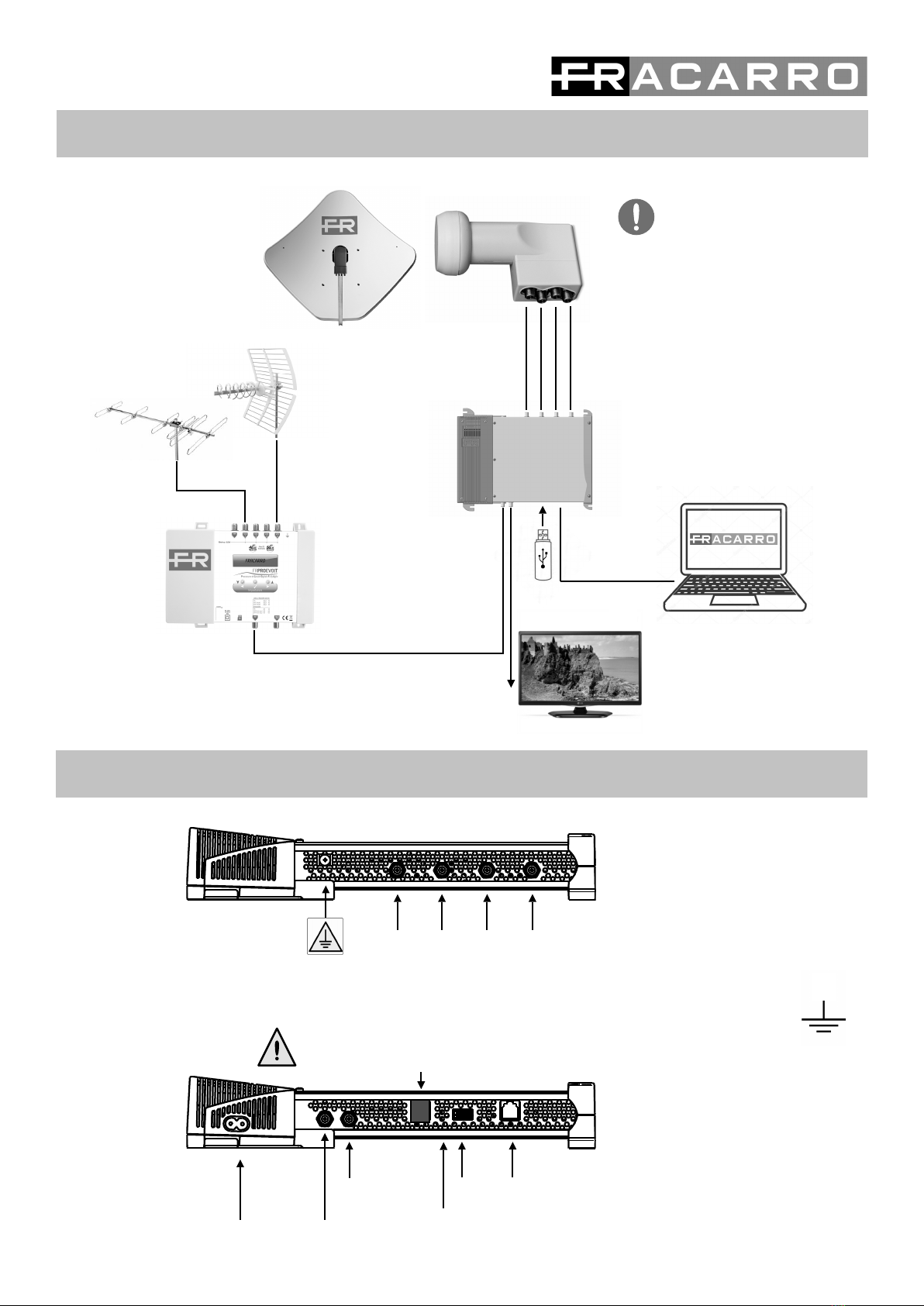
Il prodotto è dotato di:
●Presa di alimentazione elettrica bipolare;
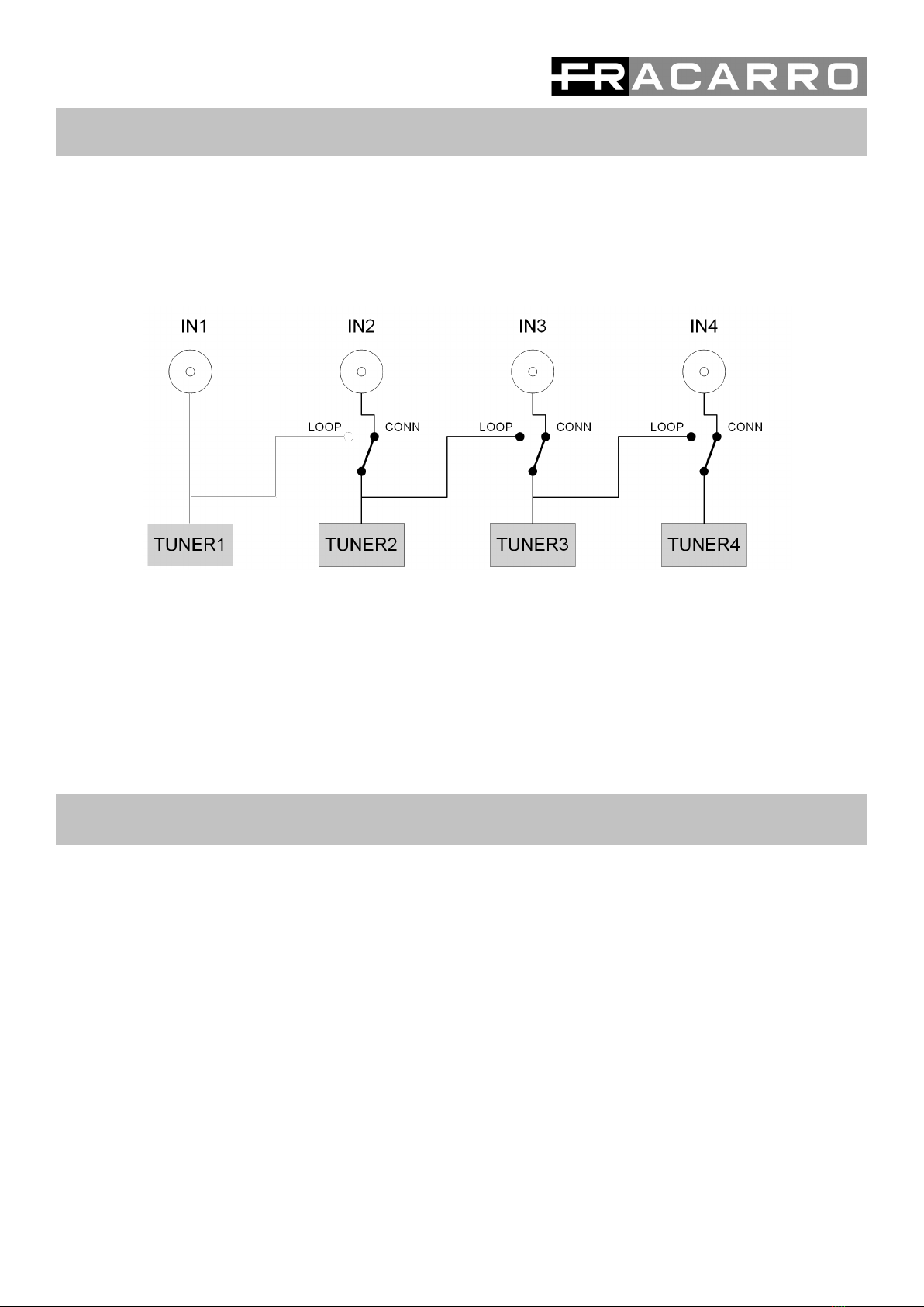
●Quattro ingressi satellitari DVB-S / DVB-S2 con gestione DiSEqC e controllo sovraccarico;
●Quattro led multicolore, uno per ogni ingresso, per l’indicazione dello stato dell’ingresso;
●Presa di alimentazione elettrica bipolare;
●Ingresso MIX che consente di miscelare il segnale generato dal dispositivo con uno proveniente da un
impianto di ricezione televisiva od altro prodotto che generi segnale RF;
●Porta di rete Ethernet 10Base-T / 100Base-TX;
●Uscita RF dei mux generati e di quanto proveniente dall’ingresso MIX;
●Porta USB host per lo storage dei file .TS, l’aggiornamento firmware e salvataggio/ripristino della
configurazione;
●LED multicolore per l’indicazione dello stato del sistema;
●Pulsante di ripristino.
PROGRAMMAZIONE D-Matrix-4S FTA: si esegue solo tramite l’interfaccia web, collegandosi con un PC da
rete locale o da remoto, tramite la porta di rete LAN.
Per le istruzioni alla programmazione dettagliata della D-Matrix-4S FTA, riferirsi al manuale
INSTALLATORE, scaricabile dal sito FRACARRO.IT alla pagina del prodotto
PULSANTE DI RIPRISTINO : la pressione di questo pulsante per un tempo >2 secondi, effettua la
cancellazione totale della centrale ed il ripristino dei valori iniziali di PASSWORD, NOME UTENTE,
INDIRIZZO DI RETE ( Indicati nella sezione INTERFACCIA WEB di questa guida).
PROCEDURA DI AUTOCONFIGURAZIONE
●Creare una configurazione via web
●esportare su file da menu Impostazioni -> Operazioni. Il nome del file sarà All_data_ora.xml
●copiare il file su chiavetta USB e rinominarlo in FR_AUTOCONF_D-MATRIX-4S_FTA.FR
(rispettare maiuscole, trattini ed estensione)
●inserire la chiavetta USB su un altro D-Matrix-4S FTA acceso
●il LED frontale lampeggerà 3 volte tra verde e arancio, poi il D-Matrix-4S FTA si riavvierà con la
nuova configurazione presente nella memoria USB.
l'autoconfigurazione non funziona se il D-Matrix viene acceso con la chiavetta USB inserita.
Deve essere inserita a macchina avviata.

4
PENTA 85
UX - QD LTE
ESEMPIO DI INSTALLAZIONE
LAN
Programazione da PC
Distribuzione TV
USB Stick
IN4 IN1 IN3 IN2
INGRESSI SAT
PORTA SERIALE RISERVATA (uso interno FR )NON
COLLEGARE NULLA SU QUESTA PORTA, UN USO IMPROPRIO
PUO’ CAUSARE IL DANNEGGIAMENTO DELLA CENTRALE
MUX OUT USB LAN per la programmazione da PC
MIX IN230 Vac
VISTA DALL’ALTO
VISTA DAL BASSO
PANORAMICA DELLA CENTRALE
Pulsante per il RIPRISTINO DI FABBRICA
D-MATRIX
4S FTA
ELIKA
BLV6F
FRPROEVOIT
Schema puramente indicativo
Il prodotto deve essere collegato
all’elettrodo di terra dell’impianto
d’antenna conformemente alla
norma EN 60728-11. La vite
predisposta per tale scopo è
contrassegnata con il simbolo.

Italiano
5
INSTALLAZIONE DEL PRODOTTO
CONTENUTO DELL’IMBALLO:
●D-MATRIX-4S FTA;
●Cavo di alimentazione;
●Guida rapida
MONTAGGIO DEL PRODOTTO:
●Utilizzando gli appositi punti di fissaggio, avvitare il prodotto alla parete, in modo che sia posizionato
verticalmente,per consentire una corretta dissipazione del calore;
●Collegare il dispositivo alla terra dell’impianto di antenna utilizzando l’apposito morsetto;
●Collegare i cavi d’antenna ai relativi ingressi;
●Se necessario inserire una unità di memoria esterna USB;
●Collegare alla rete elettrica il prodotto;
●Attendere l’avvio del dispositivo, quindi procedere alla sua configurazione;
●Verificare la corretta generazione del segnale in uscita, e lo stato di ricezione degli ingressi e del
sistema tramite appositi leds multicolore;
MONTAGGIO A MURO:
La centrale va installata facendo riferimento alle figure sottostanti, utilizzando le staffe integrate nella
meccanica del prodotto. Si preveda lo spazio necessario per l’eventuale collegamento del cavo di
alimentazione e la corretta ventilazione del prodotto (15 cm di aria su tutti i lati). Ogni altra modalità di
installazione potrebbe compromettere il corretto funzionamento del dispositivo.
Montaggio corretto
15 cm 15 cm
15 cm
15 cm

6
Gli ingressi supportano la ricezione di segnali satellite DVB-S/DVB-S2, sono in grado di fornire tele-alimentazione ad un
LNB e supportano la gestione di controllo DiSEqC versione 1.0. Il segnale può essere fornito ad ogni ingresso in modo
indipendente, utilizzando i quattro connettori superiori, oppure é possibile utilizzare la funzionalità loop-through, che
consente di fornire il segnale ricevuto da uno degli ingressi ai successivi, in cascata. In tal caso per gli ingressi in cascata
non sarà possibile specificare quale polarità/banda ricevere, poiché il segnale utilizzabile sarà il medesimo dell’ingresso
utilizzato come sorgente per il loop.
La tele-alimentazione LNB é in grado di erogare una corrente massima di 400mA, totale per tutti gli ingressi. Qualora
questo limite venga superato, interviene un limitatore di corrente, il quale provvede a disabilitare temporaneamente la
tele-alimentazione su tutti gli ingressi, riabilitandoli poi ad uno ad uno, fino ad identificare l’ingresso (o gli ingressi) che
provocano il problema. La tele-alimentazione e la ricezione da tali ingressi viene infine disabilitata, mentre la funzione
loop rimane attiva; viene quindi acceso il led con colore rosso corrispondente all’ingresso in sovraccarico. La ricezione
dagli ingressi in errore puòessere ripristinata, dopo aver risolto il guasto nell’impianto, disabilitando e riabilitando
l’ingresso, oppure riavviando la D-Matrix-4S FTA.
LED MULTICOLORE DI INDICAZIONE STATO
D-MATRIX-4S FTA è provvista di quattro led multicolore sul lato superiore (uno per ogni ingresso), per
l’indicazione dello stato di ricezione dei segnali da satellite, ed un led multicolore sul lato inferiore per
l’indicazione dello stato del sistema. Di seguito il significato di ogni led.
COLORI LED PER STATO INGRESSI
Spento: ingresso spento
Arancio: ingresso attivo in attesa di aggancio
Verde: ingresso attivo e agganciato
Rosso: ingresso in sovra-assorbimento
COLORI LED PER STATO SISTEMA (durante l’inizializzazione)
Arancio: boot sistema
Rosso: avvio applicazioni
Verde: sistema avviato senza errori
COLORI LED PER STATO SISTEMA (sistema avviato)
Verde: situazione normale
Arancio: anomalia
Rosso lampeggiante: fase di aggiornamento e/o recovery
PANORAMICA INGRESSI RF

Italiano
7
PROGRAMMAZIONE TRAMITE INTERFACCIA WEB
Il dispositivo viene configurato tramite interfaccia web. Dopo aver impostato i parametri di rete tramite il
pannello frontale ed aver connesso il dispositivo ad una rete locale, o ad un PC tramite cavo LAN è possibile
operare tramite browser web ( Consigliato Chrome ), digitando l’indirizzo IP della centrale.
ESEMPIO DI CONFIGURAZIONE DIRETTA CON PC:
Modificare l’indirizzo IP della D-MATRIX-4S FTA, inserendo un valore alla stessa sotto rete
impostata nelle proprietà della scheda di rete locale del PC, di seguito si aprirà la”Finestra di
autenticazione”
Parametri da impostare nelle proprietà della scheda di rete del PC:
•INDIRIZZO IP : 192.198.1.2
•SUBNET MASK: 255.255.255.0
•GATEWAY: 192.168.1.1
Parametri di fabbrica nelle impostazioni di rete del D-MATRIX-4S FTA:
•INDIRIZZO IP : 192.168.1.100
•SUBNET MASK: 255.255.255.0
•GATEWAY: 192.168.1.1
- NOME UTENTE : admin
- PASSWORD : 1234
Confermando con
ACCEDI
apparirà la pagina di
STATO
, dalla quale sarà possibile accedere a
tutta la programmazione della
D-Matrix-4S FTA
.
Finestra di autenticazione con PARAMETRI DI FABBRICA
admin
1234
Pagina iniziale di stato della D-MATRIX 4S-FTA

8
SAFETY WARNING
The product must only be installed by qualified persons, according to the local safety standards and regulations.
Fracarro Radioindustrie is free from all civil and criminal responsibilities due to breaches of the current legislation
derived from the improper use of the product by the installer, user or third parties. The product must be used in full
compliance with the instructions given in this manual in order to protect the operator against all possible injuries and
the product from being damaged. Never remove the lid of the product as there are live parts inside.
Earth screw symbol of the antenna
Class II symbol with a functional earth connection
Refer to the INSTALLER’S MANUAL that can be downloaded from the website
FRACARRO.IT on the product page to get more information about the TECHNICAL
SPECIFICATIONS.
Installation warnings
●The product must not be exposed to any dripping or splashing and thus it should be installed indoors and in a
dry location.
●Humidity and condensation could damage the product. In case of condensation, wait until the product is dry
before using it.
●Handle the product carefully. Impacts can damage the product.
●Leave enough space around the product to ensure sufficient ventilation.
●Excessive temperatures and/or an overheating may affect the performance and the life of the product.
●Don’t install the product above or near any heat sources, in dusty places or where it might come into contact
with corrosive substances..
●In the event that the unit is fixed to the wall, use the proper screw anchors suitable to the characteristics of
the fixing support. The wall and the anchoring system must be able to support at least 4 times the weight of
the unit.
●Warning: to avoid injury, this appliance must be secured to the wall / floor depending on the installation
instructions.
●For "PERMANENTLY INSTALLED APPLIANCES", an easily accessible cutting device must be added to the
exterior of the appliance; for "APPLIANCES WITH A POWER PLUG", the socket must be installed close to the
appliance and easily accessible.
●The product must be connected to the grounding electrode of the antenna system in compliance with
standard EN 60728-11.
The screw provided for this purpose is marked with the symbol
●We recommend that you comply with the provisions of standard EN 60728-11 and do not connect this screw
to the Protective Earth of the electricity supply.
General warnings
In the event of a malfunctioning, do not try to fix the product as the guarantee would be invalidated.
Although the information given in this manual has been prepared carefully and thoughtfully, Fracarro
Radioindustrie S.r.l. reserves the right to modify it without notice and to improve and/or modify the product
described in this manual. See the website www.fracarro.com to have information relevant to the technical
support and product guarantee.

English
9
PRODUCT DESCRIPTION
D-MATRIX-4S FTA is a unit that enables generating two modulated multiplexes according to the DVB-T or
DVB-C standards using streams received from four satellite transponders (DVB-S or DVB-S2), or read from
transport stream .TS file, contained in an external USB drive. The .TS files can be obtained by converting any
audio/video file into the right format, using a PC conversion program.
The modulator is full-band and therefore can independently modulate the 4 mux on arbitrary frequencies in
the VHF-S-UHF (114 ÷ 858 MHz) bands.
ATTENTION: the four MUX are not independent but are linked in pairs (MUX 1 / MUX 2) - (MUX 3 / MUX 4)
by the channel (or frequency) parameters, bandwidth and output level: if the output channel of MUX 1 (or
MUX 3) is set, the output channel of MUX 2 (or MUX 4) will be automatically set to the next adjacent channel
set for MUX 1 (or MUX 3).
If the output channel of MUX 2 (or MUX 4) is set, the output channel of MUX 1 (or MUX 3) will be automatically
set to the previous adjacent channel. Similarly, if a different value is set for the bandwidth or the output level
of MUX 1(or MUX 3), the same value will be set for MUX 2 (or MUX 4) and vice versa.
The product is equipped with:
●Bipolar electric power socket;
●Four DVB-S / DVB-S2 satellite inputs with DiSEqC management and overload control
●Four multicolour leds, one for each input, indicating the input status
●MIX input that enables mixing the signal generated from the device with one coming from a TV reception
system or other product that generates RF signals
●Ethernet 10base-T / 100base-TX Ethernet port
●RF output of the generated mux and whatever comes from the MIX input.
●USB host port for .TS file storage, the firmware update and configuration save/reset
●Multicolour led indicating the system status
●Reset button (internal)
RESTORE BUTTON: keep this button pressed for more than 2 seconds to delete the unit settings completely
and restore the factory parameters such as PASSWORD, USERNAME and NETWORK ADDRESS (given in
the WEB INTERFACE section of this guide).
SELF-CONFIGURATION PROCEDURE
●Create a configuration by web
●Export to a file from the Settings -> Operations menu. The file name will be All_data_ora.xml
●Copy the file to a USB stick and name it FR_AUTOCONF_D-MATRIX-4S_FTA.FR (please pay
attention to lower case letters, dashes and extension)
●Insert the USB stick into another D-Matrix-4S FTA that must be switched on
● the front LED will flash 3 times in green and orange and then D-Matrix-4S FTA will reboot
with the new configuration from the USB memory.
D-Matrix-4S FTA PROGRAMMING: can only be performed using the web interface, connecting
to a local or remote PC network, by means of a LAN network port.
For detailed programming instructions for the D-Matrix-4S FTA, please refer to the INSTALLER’S
MANUAL, which you can download from the product page found at FRACARRO.IT.
The self-configuration does not work if the D-Matrix is switched on after the USB stick is inserted.
Insert the USB stick while the unit is on.

10
PENTA 85
UX - QD LTE
INSTALLATION EXAMPLE
LAN
Programming fromPC
TV distribution
USB Stick
IN4 IN1 IN3 IN2
SAT INPUT
Reserved serial port (Fracarro’s internal use)
don’t connect anything to this port; improper use
can damage the unit.
MUX OUT USB LAN Programming fromPC
MIX IN230 Vac
TOP VIEW
BOTTOM VIEW
OVERVIEW OF THE UNIT
Button to RESTORE FACTORY SETTINGS
D-MATRIX
4S FTA
ELIKA
BLV6F
FRPROEVOIT
The diagram is just an example
The product must be connected
to the antenna line earth plate, in
compliance with the EN60728-11
standard. The earth screw is indi-
cated with the symbol.

English
11
PRODUCT INSTALLATION
CONTENTS OF THE PACKAGING:
●D-MATRIX-4S FTA
● Power cord
●Quick guide
PRODUCT ASSEMBLY:
●By using the specific fixing points, screw the product to the wall so that it is vertical to allow correct
heat dissipation.
●Connect the earth terminal to the antenna earth line.
●Connect the antenna cables to their inputs.
●If required, insert an external USB drive
●Connect the product to the electricity supply
●Wait for the device to start and it can then be configured.
●Check the output signal is generated correctly and the reception status of the inputs and system on
the specific multicolour leds.
WALL MOUNTING:
Install the unit as shown in the figures, using the brackets incorporated in the product mechanics. Allow
sufficient space to connect the power cable and for correct ventilation (15 cm airspace on all sides). Any
other type of installation could affect the correct functions of the device.
Correct mounting
15 cm 15 cm
15 cm
15 cm

12
The inputs support the reception of the DVB-S/DVB-S2 satellite signals and they can power supply an LND
remotely; they support the management of DiSEqC control, version 1.0. The signal can be provided to each
input independently, using the four upper connectors, or the loop-through function can be used, which enables
providing a signal received from one of the subsequent inputs in cascade. In this case, the cascade inputs
cannot have the reception polarity/band specified, because the signal that can be used will be the same as
the input used as source for the loop.
The LNB remote power feed is able to supply a maximum current of 400 mA, total for all the inputs. If this
limit is exceeded, a current limiter triggers, which temporarily deactivates the remote power feed on all the
inputs, reactivating them one at a time, until the input (or inputs) causing the problem is identified. The remote
power feed and reception from these inputs is finally deactivated, while the loop function remains active. The
red led then lights up corresponding to the overloaded input. Reception from the error inputs can be reset
after solving the system malfunction, deactivating and reactivating the input, or by restarting the D-Matrix-4S
FTA.
MULTICOLOUR STATUS LEDS
D-MATRIX-4S FTA has four multicolour leds on the top (one for each input), to indicate the sat signal
reception status, and one multicolour led on the bottom showing the system status.
The following table gives a useful summary to interpret the lighted leds.
LED COLOURS OF INPUT STATUS
Off: input off
Orange Input active waiting to lock
Green: Input active and locked
Red: Input overloaded
LED COLOURS OF SYSTEM STATUS (during initialisation)
Orange: boot system
Red: begin applications
Green: system started without errors
LED COLOURS OF SYSTEM STATUS (system started)
Green: normal
Orange: anomaly
Flashing red: update and/or recovery phase
RF INPUTS VIEW

English
13
PROGRAMMING BY WEB INTERFACE
The device can be configured using the web interface. After configuring the network parameters
using the front panel and connecting to the local network, or to a PC using a LAN cable, the web
browser can be used (Chrome is recommended) by entering the unit IP address.
ESEMPIO DI CONFIGURAZIONE DIRETTA CON PC:
Change the IP address of D-MATRIX-4S FTA using a value that belongs to the same subnet as the
one set in the local net card on the PC. Then the “authentication window” will appear:
Parameters set in the PC network card:
•IP ADDRESS : 192.198.1.2
•SUBNET MASK: 255.255.255.0
•GATEWAY: 192.168.1.1
Factory parameters in the network settings of D-MATRIX-4S FTA:
•IP ADDRESS : 192.168.1.100
•SUBNET MASK: 255.255.255.0
•GATEWAY: 192.168.1.1
- USER NAME : admin
- PASSWORD : 1234
By confirming with ENTER, the STATUS page will
appear, from which it will be possible to access
all the programming of the D-Matrix-4S FTA.
Authentication window with FACTORY PARAMETERS
adminadmin
1234
Status page of D-MATRIX 4S-FTA
Username
Access

14
CONSIGNES DE SÉCURITÉ
L’installation du produit doit être effectuée par du personnel qualifié conformément aux lois et aux normes locales
sur la sécurité. Par conséquent, Fracarro Radioindustrie décline toute responsabilité civile ou pénale dérivant de
violations des normes juridiques en vigueur et de l’utilisation incorrecte du produit de la part de l’installateur, de
l’utilisateur ou de tiers. Le produit doit être installé en suivant les indications fournies, afin de préserver l’opérateur
d’éventuels accidents et le produit d’éventuels endommagements. Ne pas ôter le couvercle du produit ; des pièces
sous tension dangereuse peuvent être accessibles lors de l'ouverture de la coque.
Symbole de mise à la terre de l’antenne
Symbole de classe II avec une mise à la terre fonctionnelle
Pour les SPÉCIFICATIONS TECHNIQUES se référer au MODE D'EMPLOI INSTALLATEUR
pouvant être téléchargé sur le site internet FRACARRO.IT à la page du produit.
Avertissements concernant l’installation
●Le produit ne doit pas être exposé à l’égouttement ou aux éclaboussures d’eau et il doit donc être installé
dans un endroit sec, à l’intérieur.
●L’humidité et les gouttes de condensation, pourraient endommager l’appareil. En cas de condensation,
attendre que le produit soit complètement sec avant de l’utiliser.
●Manier avec soin. Les chocs pourraient endommager le produit.
●Laisser de l’espace autour du produit pour garantir une ventilation suffisante.
La température excessive de fonctionnement et/ou un réchauffement excessif peuvent nuire au
fonctionnement et à la durée du produit.
●Ne pas installer le produit sur ou près des sources de chaleur, dans des endroits très poussiéreux ou en
contact avec des substances corrosives.
●En cas de montage mural, utiliser des chevilles à expansion correspondant aux caractéristiques du support de
fixation. La paroi et le système de fixation doivent être en mesure de supporter au moins 4 fois le poids de
l’appareil.
●Attention : Pour éviter de se blesser, ce produit doit être fixé au mur/sol en suivant les instructions de
montage.
●Pour des « APPAREILS INSTALLÉS DE FAÇON PERMANENTE », un dispositif de sectionnement facilement
accessible doit être incorporé à l’extérieur de l’appareil ; pour des « APPAREILS AVEC UNE PRISE DE
COURANT », la prise doit être installée à proximité de l’appareil et être facilement accessible.
●Le produit doit être raccordé à l’électrode de mise à la terre de l’antenne conformément à la norme EN 60728-
11.
La vis prévue à cet effet est marquée du symbole
●Il est conseillé de respecter les dispositions de la norme EN 60728-11 et de ne pas relier cette vis à la mise à
Avertissements généraux
En cas de dysfonctionnement, n'essayez pas de réparer le produit car la garantie serait invalidée.
Bien que les informations données dans ce manuel aient été préparées avec soin et réflexion, Fracarro
Radioindustrie S.r.l. se réserve le droit de le modifier sans préavis et d'améliorer et / ou de modifier le produit
décrit dans ce manuel. Consultez le site Web www.fracarro.com pour obtenir des informations relatives au
support technique et à la garantie du produit.

Français
15
DESCRIPTION DU PRODUIT
D-MATRIX-4S FTA est un appareil qui permet de générer deux couples de multiplexeurs adjacents modulés
selon les standards DVB-T ou DVB-C, en utilisant des stream en provenance de quatre transpondeurs satellites
(DVB-S ou DVB-S2) ou lus par des fichiers transport stream .TS, contenus dans une unité de mémoire externe
USB. Les fichiers .TS peuvent être obtenus en convertissant n’importe quel fichier audio/vidéo au format
approprié, à l’aide d’un programme de conversion pour PC. Le modulateur est à bande complète : il est donc
possible de moduler les 4 mux sur des fréquences arbitraires dans les bandes VHF-S-UHF (114 ÷ 858 MHz).
NB : les quatre MUX ne sont pas indépendants des paramètres canal (ou fréquence), largeur de bande et
niveau de sortie, mais ils sont liés par couples (MUX 1-MUX 2) – (MUX 3-MUX 4) : si le canal en sortie du
MUX 1 (ou MUX 3) est programmé, le canal en sortie du MUX 2 (ou MUX 4) sera programmé automatiquement
au MUX adjacent suivant à celui programmé pour le MUX 1 (ou MUX 3). En revanche, si on programme le
canal en sortie du MUX 2 (ou MUX 4), le canal en sortie du MUX 1 (ou MUX 3) au MUX adjacent précédent
sera programmé automatiquement. De la même façon, en programmant une valeur différente pour la largeur
de bande ou pour le niveau de sortie de MUX 1 (ou MUX 3), la même valeur sera programmée pour le MUX
2 (ou MUX 4), et vice-versa.
Le produit est équipé de :
●Prise d’alimentation électrique bipolaire ;
●Quatre entrées satellites DVB-S / DVB-S2 avec une gestion DiSEqC et un contrôle de la surcharge ;
●Quatre LED multicolores, une pour chaque entrée, afin d’indiquer l’état d’entrée ;
●Entrée MIX permettant de mélanger le signal produit par le dispositif à un signal provenant d’un
équipement de réception télévisée ou un autre produit produisant un signal RF ;
●Port Ethernet 10Base-T / 100Base-TX ;
●sortie RF des mux générés et de ce qui provient de l’entrée MIX ;
●port USB host pour le stockage des fichiers .TS, la mise à jour firmware et la sauvegarde/restauration de
la configuration ;
●LED multicolore indiquant l’état du système ;
●Bouton de réinitialisation.
BOUTON DE RÉINITIALISATION: en appuyant sur ce bouton pendant plus de 2 secondes, tous les réglages
de l’unité centrale seront supprimés et les réglages initiaux MOT DE PASSE, IDENTIFIANT, ADRESSE DE
RÉSEAU (Indiqués dans la section INTERFACE WEB de ce guide) seront rétablis.
PROCÉDURE DE CONFIGURATION AUTOMATIQUE
●Créer une configuration via web
●Exporter sur un fichier du menu Réglages -> Opérations. Le nom du fichier sera All_data_ora.xml
●Copier le fichier sur une clé USB et le renommer en FR_AUTOCONF_D-MATRIX-4S_FTA.FR
(respecter les majuscules, les tirets et l’extension)
●Introduire la clé USB sur un autre D-Matrix-4S FTA allumé
●La LED frontale clignotera 3 fois vert et orange, puis D-Matrix-4S FTA démarrera de nouveau
avec la nouvelle configuration présente dans la mémoire USB.
PROGRAMMATION D-Matrix-4S FTA : la programmation ne peut être effectuée que par l’interface
web, en se connectant à un PC depuis un réseau local ou à distance par le biais du port de réseau
LAN. Pour les instructions sur la programmation détaillée de D-Matrix-4S FTA, se référer au
mode d’emploi INSTALLATEUR pouvant être téléchargé sur le site internet FRACARRO.IT à la
page du produit.
La configuration automatique ne fonctionne pas si D-Matrix est allumé lorsque la clé USB est
insérée.

16
PENTA 85
UX - QD LTE
EXEMPLE D’INSTALLATION
LAN
Programmation depuis
Distribution TV
Clé USB
IN4 IN1 IN3 IN2
ENTRÉES SAT
PORT SÉRIE RÉSERVÉ (utilisation interne FR)
AUCUN DISPOSITIF NE DOIT ÊTRE BRANCHÉ À CE PORT, UNE UTILISATION NON
MUX OUT USB LAN pour la programmation
MIX IN230 Vac
VUE DE DESSUS
VUE DU DESSOUS
VUE DE L’UNITÉ CENTRALE
Bouton de RÉINITIALISATION USINE
D-MATRIX
4S FTA
ELIKA
BLV6F
FRPROEVOIT
Schéma purement indicatif
Le produit doit être raccordé à
l’électrode de mise à la terre de
l’antenne conformément à la norme
EN 60728-11. La vis prévue à cet
effet est marquée du symbole

Français
17
INSTALLATION DU PRODUIT
CONTENU DE L’EMBALLAGE :
●D-MATRIX-4S FTA ;
●Câble d'alimentation ;
●Guide rapide
MONTAGE DU PRODUIT :
●En utilisant les points de fixation prévus à cet effet, visser le produit au mur, de sorte qu’il soit
positionné verticalement, pour permettre une bonne dissipation de la chaleur ;
●Relier le dispositif à la terre de l’antenne à l’aide de la borne prévue à cet effet ;
●Relier les câbles d'antenne aux entrées correspondantes ;
●Si nécessaire, introduire une unité de mémoire externe USB ;
●Relier le produit au secteur ;
●Attendre le démarrage du dispositif, puis le configurer ;
●Vérifier que la génération du signal en sortie est correcte, ainsi que l’état de réception des entrées et du
système à l’aide des LED multicolores spécifiques.
MONTAGE MURAL:
L’unité centrale doit être installée en suivant les instructions des figures ci-dessous, à l’aide des étriers intégrés
dans la mécanique du produit. Prévoir l’espace nécessaire pour l’éventuelle connexion du câble d’alimentation
et la bonne aération du produit (15 cm d’air de tous les côtés). Toute autre modalité d’installation pourrait
nuire au bon fonctionnement du dispositif.
Montage correct
15 cm 15 cm
15 cm
15 cm

18
Les entrées supportent la réception de signaux satellites DVB-S/DVB-S2 ; elles sont en mesure d’alimenter
à distance un LNB et supportent la gestion de contrôle DiSEqC version 1.0.
Le signal peut être fourni à chaque entrée de façon indépendante, en utilisant les quatre connecteurs
supérieurs, ou bien il est possible d’utiliser la fonction loop-through, qui permet de fournir le signal reçu par
une des entrées aux suivantes, en cascade. Dans ce cas, pour les entrées en cascade, il ne sera pas possible
de préciser la polarité/bande à recevoir, parce que le signal utilisable sera le même que celui de l’entrée
utilisée comme source pour le loop.
L’alimentation à distance LNB est en mesure de fournir un courant maximum de 400mA, total pour toutes
les entrées. Si cette limite est dépassée, un limiteur de courant intervient en désactivant temporairement
l’alimentation à distance sur toutes les entrées, puis en les réactivant une par une, jusqu’à identifier l’entrée
(ou les entrées) à l'origine du problème. L’alimentation à distance et la réception de ces entrées est ensuite
désactivée, tandis que la fonction loop reste active ; la LED rouge correspondant à l'entrée en surcharge
s'allume alors. La réception des entrées en erreur peut être rétablie, après avoir résolu la panne au niveau de
l’équipement, en désactivant ou réactivant l’entrée, ou bien en redémarrant le D-Matrix-4S FTA.
LED MULTICOLORE D’INDICATION D’ÉTAT
D-MATRIX-4S FTA est doté de quatre LED multicolores dans le haut (une pour chaque entrée), qui indiquent
l’état de réception des signaux provenant des satellites, et d’une LED multicolore dans le bas, qui indique
l’état du système. La signification de chaque LED est indiquée ci-dessous.
COULEURS DES LED POUR L’ÉTAT DES ENTRÉES
Éteinte : entrée éteinte
Orange : entrée active en attente de connexion
Vert : entrée active et connectée
Rouge : entrée en sur-absorption
COULEURS DES LED POUR L’ÉTAT DU SYSTÈME (pendant l’initialisation)
Orange : démarrage système
Rouge : démarrage applications
Vert : système démarré sans erreurs
COULEURS DES LED POUR L’ÉTAT DU SYSTÈME (système démarré)
Vert : situation normale
Orange : anomalie
Rouge clignotant : phase de mise à jour et/ou reprise
VUE DES ENTRÉES RF

Français
19
PROGRAMMATION PAR INTERFACE WEB
Il est possible de configurer le dispositif par interface web.
Après avoir configuré les paramètres de réseau à l’aide du panneau frontal et avoir connecté le
dispositif au réseau local, ou à un PC par le biais d’un câble LAN, il est possible de travailler avec un
navigateur internet (il est conseillé d’utiliser Chrome) en tapant l’adresse IP de l’unité centrale.
EXEMPLE DE CONFIGURATION DIRECTE À PARTIR D’UN PC :
Modifier l’adresse IP de D-MATRIX-4S FTA, en saisissant une valeur au même sous-réseau
programmé dans les propriétés de la carte de réseau local du PC, la « Fenêtre d’authentification »
sera affichée.
Paramètres programmés dans les propriétés de la carte de réseau du PC :
•ADRESSE IP : 192.198.1.2
•SUBNET MASK : 255.255.255.0
•GATEWAY : 192.168.0.1
Paramètres à modifier dans les configurations de réseau de D-MATRIX-4S FTA :
•ADRESSE IP : 192.168.1.100
•SUBNET MASK : 255.255.255.0
•GATEWAY : 192.168.1.1
- NOM IDENTIFIANT : admin
- MOT DE PASSE : 1234- PASSWORD : 1234
Confirmer par
ACCÉDER
, la page-écran d’
ÉTAT
apparaîtra. Depuis cette page il sera possible d’accéder
à toute la programmation de
D-Matrix-4S FTA
.
Fenêtre d’authentification avec les PARAMÈTRES D’USINE
admin
1234
Status page of D-MATRIX 4S-FTA
Identifiant
Accéder
Mot de passe

20
SICHERHEITSHINWEISE
Das Produkt darf ausschließlich von qualifiziertem Fachpersonal nach Vorgabe der vor Ort geltenden
Sicherheitsbestimmungen und Sicherheitsvorschriften installiert werden. Die Firma Fracarro Radioindustrie Spa ist
deshalb von jeder zivil- und strafrechtlichen Haftung bei Verstößen gegen die maßgeblichen gesetzlichen
Bestimmungen und bei unsachgemäßem Gebrauch des Produkts durch den Installateur, durch den Benutzer oder
durch Dritte befreit. Die Installation des Produkts muss unter Beachtung der Installationsanweisungen erfolgen, um
den Bediener vor eventuellen Verletzungen und das Produkt vor eventuellen Schäden zu schützen. Auf keinen Fall das
Gehäuse des Produkts öffnen. Bei Öffnen vom Gehäuse sind gefährliche spannungsführende Teile zugänglich.
Symbol der Erdungsanlage der Antenne
Symbol der Klasse II mit einem Funktionserdungsanschluss
Die TECHNISCHEN SPEZIFIKATIONEN können dem INSTALLATIONSHANDBUCH
entnommen werden, das auf der Webseite FRACARRO.IT auf der Produktseite
heruntergeladen werden kann.
Installationshinweise
●Das Produkt vor Tropfwasser und Spritzwasser schützen. Das Produkt muss an einem trockenen Ort in einem
Gebäude installiert werden.
●Feuchtigkeit und abtropfendes Kondenswasser können das Produkt schädigen. Bei Auftreten von
Kondenswasser muss das Produkt vor Gebrauch vollständig getrocknet werden.
●Das Produkt mit Sorgfalt handhaben. Das Produkt kann durch Stöße beschädigt werden.
●Um das Produkt ausreichend Freiraum lassen, um für eine angemessen Belüftung zu garantieren.
●Zu hohe Temperaturen u/o eine Überhitzung können die Funktionstüchtigkeit und die Lebensdauer des
Produkts beeinträchtigen.
●Das Produkt nicht über oder in der Nähe von Wärmequellen, an staubigen Orten oder an Orten installieren, an
denen es mit korrosiven Substanzen in Berührung kommen kann.
●Bei einer Wandmontage müssen Dübel mit geeigneten Eigenschaften für den Untergrund verwendet werden.
Die Wand und das Befestigungssystem müssen auf ein Gewicht ausgelegt sein, das mindestens dem
Vierfachen des Gewichts des Geräts entspricht.
●Achtung: Um Verletzungen zu vermeiden, muss das Gerät unter Beachtung der Installationshinweise an der
Wand oder dem Fußboden befestigt werden.
●Bei "FEST INSTALLIERTEN GERÄTEN" muss ein leicht zugänglicher Trennschalter außen am Gerät installiert
werden. Bei "GERÄTEN MIT STROMSTECKER" muss die Steckdose in der Nähe des Geräts installiert und leicht
zugänglich sein.
●Das Produkt muss nach Vorgabe der Norm DIN EN 60728-11 an die Erdungsklemme der Antennenanlage
angeschlossen werden.
Die Erdungsschraube ist mit dem entsprechenden Symbol gekennzeichnet
●Die Vorgaben der Norm Norm DIN EN 60728-11 müssen beachtet werden. Die Erdungsschraube darf nicht
direkt an den Schutzleiter vom Stromnetz angeschlossen werden.
Allgemeine Warnungen
Versuchen Sie im Falle einer Fehlfunktion nicht, das Produkt zu reparieren, da sonst die Garantie erlischt.
Obwohl die in diesem Handbuch enthaltenen Informationen mit Sorgfalt und Sorgfalt erstellt wurden, behält
sich Fracarro Radioindustrie S.r.l. das Recht vor, diese ohne vorherige Ankündigung zu ändern und das in
diesem Handbuch beschriebene Produkt zu verbessern und / oder zu modifizieren. Besuchen Sie
www.fracarro.com, um Informationen zum Produktsupport und zur Garantie zu erhalten.
This manual suits for next models
1
Table of contents
Languages:
Other Fracarro Control Unit manuals
Popular Control Unit manuals by other brands

AXIOMTEK
AXIOMTEK AX92920 Quick installation guide

Burkert
Burkert 2730 Series operating instructions

Aumuller
Aumuller EMB 7300 Installation and commissioning instructions

LOVATO ELECTRIC
LOVATO ELECTRIC EXP10 14 instruction manual

Siemens
Siemens Simatic ET200pro Product information

Reliance electric
Reliance electric GV3000 instruction manual