Francis Searchlights L300RC Operating manual

CONTENTS
1. Introduction
2. Safety Precautions
3. Technical Information
4. Unpacking and Installation Instructions
5. Electrical Installation
6. Start-up and Operating
6.1. FBUS Data & Panel Addresses
7. Fault Finding
7.1. Problems After Installation
7.2. Obtaining Fault Status
8. Maintenance and Servicing
9. Wiring Diagram & General Assembly
10. Spare Parts List
General Information:
Francis Searchlights Ltd
Union Road, Bolton, BL2 2HJ
United Kingdom
T: 00 44 (0)1204 558 960
W: www.francis.co.uk

1 –Introduction
It is imperative that this manual is read carefully and understood before
installing your equipment. For your future reference please keep this manual
in a safe place.
Thank you for specifying a product from the Francis Searchlights range. All Francis products are
designed to give complete customer satisfaction and are manufactured to the highest engineering
standards to ensure optimum performance and service life.
The Francis LITE range combines features proven over many years in the most hazardous
conditions in both marine and land installations.
To prolong the life and performance of your product, we recommend that you only specify Francis
Searchlights spare parts. This will also ensure that any warranties on your equipment will not be
invalidated. Information on spares ordering and parts is provided in this manual.
Should you ever need to contact Francis Searchlights Ltd. regarding your equipment, please
always quote the Product Number and Serial Number of the product you have, this is located on
the name plate on the lid of the driver box.
In order that the searchlight operates correctly it is imperative that competent personnel are
responsible for the installation, operation, and servicing of this equipment. Failure to adhere to this
advice may cause premature failure or incorrect operation of the searchlight, which may damage
the equipment or cause personal injury.

2 –Safety Precautions
The following instructions must be adhered to, to ensure a safe working environment and
the safety of the user.
Note: When unpacking or manoeuvring the searchlight into its fixing position, suitable
lifting points must be used to prevent damage to the equipment or personal injury.
•Only suitably qualified personnel may install the products.
•Never look directly into an illuminated searchlight as this may cause severe damage to
eyesight. If it is necessary to inspect a searchlight whilst in operation, always wear suitable
protective goggles.
•Searchlights get hot. Never touch the unit when lit and always allow 15 to 20 minutes for
cooling down after turning the searchlight off.
•Never place anything on or cover the searchlight when in use.

3 –Technical Information
Electrical
Input voltage:
110 VAC 240 VAC.
Input current:
2A 1A
Driver output voltage:
48v DC Max
Driver current:
4.8A Max
Wattage:
234w
Dimensions
Height:
945mm
Width:
414mm
Depth:
546mm
Weight: Searchlight –Driver Box
34Kgs –4Kgs
Searchlight Performance
LED power:
234w
Range @ 1 Lux:
3047m
LED life (approx.)
20,000h
Divergence:
4°-10°
Colour temperature:
6000K
Luminous flux:
35,537 lumens
Searchlight movement
Pan rotation:
365°
Tilt elevation:
Up 35° & Down 40°
Pan speed:
Variable Speed 1 to 19°/sec
Tilt Speed:
Variable Speed 1 to 6°/sec
Material, colour, IP rating
Searchlight barrel head:
Aluminium BSEN485 5251
Gearbox housing:
Stainless Steel BS1449 304S31
Crutch:
Stainless Steel BS1449 304S11
Paint finish powder coated & stove enamel paint:
Ash Grey BS4800 00A01, May Green RAL 6017
IP rating:
Searchlight IP56 –PSU IP66
Operating temperature:
-50°C to +50°C
Certification approval:
Lloyds TA:
IEC 60945: 2002
Russian Maritime Register of Shipping:
Parts XI & XVII, Part IV
ISO9001 2015:
Quality Management System

4 –Unpacking and Installation Instructions
The following instructions should be read and fully understood prior to installing the equipment to
ensure that the correct procedures are followed, and all safety precautions are observed.
Note: If the equipment has been in storage for a considerable amount of time, it is
advisable to conduct a routine maintenance check on all parts before installation.
Safety Precautions
This equipment should not be connected to an electrical supply before being installed. Installation
procedures should be adhered to, to ensure a safe working environment and reduce the risk of
damage or personal injury.
Preparing the Mounting Position
Mark out and drill the fixing holes through the deck. If anti-vibration mounts are to be fitted, the
fixing holes for the mounts should also be marked out and drilled. Prior to manoeuvring the
searchlight into its’ fixing position, the AV mounts should be fitted to the base. When in the desired
position, bolt the searchlight firmly down. On an uneven surface it may be necessary to use a
suitable sealant such as silicone, to ensure a weatherproofed joint.
Please refer to the drawing C29556 for the Joystick Panel cut out size, which you can find at the
back of this manual.
Rear of Searchlight Base Fixings, 4 Holes Ø12.5
Equally Spaced on a Ø 290.00

5 –Electrical Installation
For safety purposes, only competent personnel should perform the electrical
installation. All equipment should be installed to current Electrical
Regulations and Standards.
Referring to wiring diagram C28381 (at the back of the manual), a supply is fed to the driver box,
which then provides a common feed to the motor gearbox, searchlight, and joystick panel.
The searchlight has been pre-wired with 3 meters of cable from the motor gearbox to driver box
provided. The searchlight head is pre-wired along with the connecting cable to the motor gearbox.
Cables required to be connected by the customer: -
•2 pair twisted 0.22mm 100ohm screened cable from the joystick panel to the driver box.
•Mains supply cable to the driver box.
3m of cable supplied by
Francis.
12 core 1.5mm
2 pair twisted screened.
mains supply cable
Supplied by
customer.
2 pair twisted
screened cable,
supplied by
customer.
Searchlight
Joystick Panel
Driver Box

To obtain the maximum light output from the searchlight, it is essential that the full operating
voltage of the LED fitted be applied to the LED contacts.
Method of Electrical Connection
•Disconnect the supply before working on the electrical system.
•The searchlight must be connected to a fused electrical supply, using suitably sized cable.
•If the searchlight is located a considerable distance from the supply, provision must be
made in the cable size to overcome the voltage drop.
The following table below indicates the maximum length of cable to be used for the supply cable,
from the mains supply to the driver box.
Searchlight
115v
234w
240v
234w
Cable Size
(mm²)
Distance
Max
Distance
Max
1.5
85M
355M
2.5
143M
600M
The following table below indicates the maximum length of cable to be used for DC cable, from the
searchlight to the driver box.
Searchlight
HV
Cable Size (mm²)
Distance
Max
12 core 1.5mm doubling up dc cores
26M
•Whenever possible cable terminations should be made below deck and with approved
terminal devices.
•If a spare auxiliary fuse or circuit breaker is not available, one of the correct type/ratings
should be fitted and connected to a positive supply. It is advisable to locate a bus bar or
main connection and avoid any direct connection to the supply.
•For 115/240v AC products, the following colour coding system should be used for the
customer supply cable:
Brown - Live
Blue - Negative
Green/Yellow - Earth
Note: This equipment must be earthed.

6 –Start-up and Operating
Start-Up
When the main power is first applied to the searchlight, the searchlight will carry out a self-test, it
will Pan to the left limit and Tilt down to the limit, once this is complete, the searchlight will then
move to the centre and horizontal, during this please do not try and operate the searchlight while
this test is being carried out. Once the searchlight is back at centre the searchlight can then be
operated normally, by pressing the 1/0 button on the control panel.
Operating
Switch On
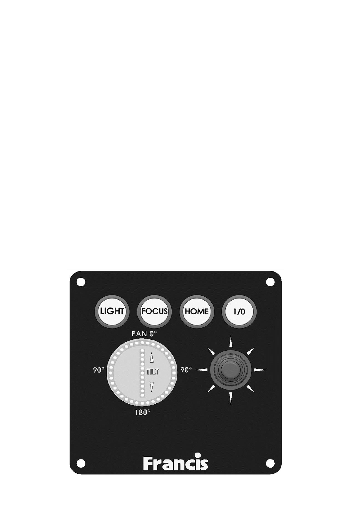
The panel is activated using the 1/0 button. This will illuminate brightly when the panel is active.
Alternate operations of the 1/0 button will switch the panel on and off.
Lamp Control
When the panel is active pressing the LIGHT button will switch the light on or off.
If the joystick panel is switched off with the 1/0 button the light will switch off.
Focus Control
The lamp focus can be adjusted using the FOCUS button. Lamp focus will adjust continuously
whilst FOCUS is pressed.
Beam Direction
The beam direction can be adjusted using the joystick when the panel is active. Moving the
joystick left or right will pan the beam clockwise or anticlockwise.
Moving the joystick up or down will move the beam up or down. The speed of movement is
proportional to the movement of the joystick. It is possible to move the beam in both directions at
once by moving the joystick diagonally. The LED’s illuminate indicating which direction the
searchlight is travelling in. The pan movement is in a circular array of LEDs, when the LED’s start
to flash this indicates that the searchlight has reached the end of its travel in either left or right
direction. The tilt movement is illustrated with 11 vertical LED’s, the LED will also flash when the
searchlight has reached the end of its travel.
Home
The searchlight can be returned to a pre-set home position. By default, this is dead ahead with the
beam level although different positions can be programmed as described below.
To send the searchlight to the home position switch the panel off then press the HOME button.
Set New Home Position
To set a new home position move the searchlight to the new desired home position. Switch the
panel off then press the joystick down to its limit and press the LIGHT button. The current position
will now be the new home position.

Set Motion Limit
The searchlight travel can be limited in either axis or either direction. To set a new limit, switch the
panel on and move the searchlight to the desired limit position. Switch the panel off then press and
hold the FOCUS button whilst moving the joystick full travel in the direction of the desired limit.
Hold in this position for 4 seconds. For example, to set a limit to the tilt up motion; -
1. Switch panel on and drive the searchlight to desired tilt up limit position.
2. Switch panel off.
3. Press and hold the FOCUS button and hold joystick in the full up position for 4
seconds.
4. Tilt up motion will now be inhibited above the current position.
Clear Motion Limits
Motion limits as set above can be cleared by switching the panel off then pressing and holding the
FOCUS button and LIGHT buttons together for 10 seconds.
Adjusting Panel Illumination
The panel illumination and indicators intensity can be adjusted to suit ambient light levels. To
adjust the intensity, switch the panel on then switch it off with the 1/0 button and keep the 1/0
button pressed. To increase intensity, move the joystick to the right. To decrease move to the left.
Note that the 1/0 button must be kept depressed whilst the joystick is moved. All indicators will
illuminate whilst adjustments are performed. Adjustment is complete when the 1/0 button is
released.

6.1 - FBUS Data & Panel Addresses
The Francis bus (FBUS) is a custom communication protocol based on RS485 two wire bi-
directional communication hardware. The system provides a simple bi-directional link between
searchlights and joystick panels. The system allows given panels to communicate with different
searchlights and allows several panels to communicate with the same searchlight.
FBUS Address Switches
Setting Searchlight Address Value
The searchlight address is set using the Dip switches on the Speed Controller PCB located inside
the Gearbox Assembly (see drawing C29488). With the address switches using simple binary
input. Each switch has a binary value as details below; -
Dip Switch
Searchlight
10
1
9
2
8
4
7
8
6
16
If only 1 Searchlight is used, then all switches will be set to off.
The address value is the sum of the numbers above which are active when the switch is on.
For example, if switches 8 and 10 are on, and all others are off, the address value would be 5.
Note that switches 1-3 are not used for address selection and should be switched off.
Standard Joystick Panel –Control (Panel) Address
Dip
Switch
Control
Panel
1
8
2
4
3
2
4
1
EXAMPLES
Standard joystick panel –panel address set to 5
Switch 1 = Off
Switch 2 = On (Value 4 added to address)

Switch 3 = Off
Switch 4 = On (Value 1 added to address)
4 + 1 = 5
Speed control card - lamp address set to 11.
Switch 6 = Off
Switch 7 = On (Value 8 added to address)
Switch 8 = Off
Switch 9 = On (Value 2 added to address)
Switch 10 = On (Value 1 added to address)
8 + 2 + 1 = 11
ADDRESSING SYSTEM
Every searchlight must have a unique address. The addresses should be sequential and should
start from zero. If there were three searchlights in a system the addresses should be set to 0, 1
and 2.
Control panel –panel addresses use the same system being sequential and start from zero.
It is essential that all panels have a unique address with no duplication however note that
searchlights and panels can be the same address. For example, on a system with two panels and
two searchlights, the panel addresses will be 0 and 1 and the lamps addresses will be 0 and 1.
Control panel lamp addresses are defined by the system configuration. If two panels are used to
control the same searchlight, they must still have individual panel addresses, but the lamp
addresses can be set to the same address value as the searchlight which is to be controlled. Any
number of panels can control the same lamp.

Multiple Searchlights, Control Panels and Master Control Panel

7 –Fault Finding
7.1 Problems at Installation
•If the searchlight completes the Self-Test, e.g., Pan left, Tilts down then returns to centre
and the LEDs on the joystick panel are not illuminate, then please check the 4 data cables
connections on the FBUS connector located on the back of the joystick panel assembly, as
these data cables could be swapped around, you can check the voltages on the 4
connections, you should get as shown below.
o0 & + = 2.2v DC
o0 & - = 2.2v DC
o24 & 0 = 18-24v DC
•If the searchlight completes the Self-Test, e.g., Pan left, Tilts down then returns to centre
and the LEDs on the joystick panel are illuminated, but you are unable to control the
searchlight via the joystick panel, then please check the data + & - connections on the
FBUS connector located on the back of the joystick panel assembly, as these data cables
could be swapped around.
•If you have more than 1 searchlight in the installation and 2 or more searchlights are
moving at the same time in the same direction, then please check the dip switch settings on
the speed controller PCB, see Setting Searchlight Address Value.
Failure of Lamp to light
•Check that the supply is connected to the input of the LED driver and check all connections
as per the wiring diagram. On operation if the LED does not light, switch off mains supply
and check all fuses.

7.2 - Problems After Installation
Please note, if the searchlight does not complete the self-test, you will not be able to operate the
searchlight in any direction or switch the light on. Please refer to section 7.3 Obtaining Fault
Status below, to confirm the fault.
Once you have confirmed the fault via the joystick panel, please contact Francis Searchlights for
If the joystick panel is not communicating with the searchlight and none of the LED’s on the
joystick panel are lighting up, then you will need to access the speed controller PCB inside the
gearbox (see drawing C29488), to access the speed controller PCB you will need to remove the 6
off M6 screws that hold the motor top to the gearbox housing and then lift the searchlight up out of
the gearbox housing, taking care not to damage the assembly, the Status LED located near the
top of the card (labelled “STATUS”) on the speed controller PCB, shown below.
During faults normal status LED operation is overridden. The status LED will flash red several
times with the number of flashes corresponding to the specific fault. If there are multiple faults the
LED will flash accordingly with a gap between each fault flash sequence. Fault details are
provided on the next page, with the number of flashes indicated on the left.
The Status LED has several functions as detailed below.
Software Version
When power is applied to the speed control card the status LED will flash green. The number of
flashes corresponds to the software version.
FBUS Normal operation
When the system is operating from FBUS the status LED will illuminate static green. When a valid
FBUS data signal is received the LED will switch off momentarily to indicate data reception. If data
is continuous the LED will flash green slowly.
If the Status LED does not light up, then please check the 24v DC supply from the PSU within the
gearbox, as shown on drawing C29488 Item 6, if there is no output from the PSU then this will
need to be replaced.

7.3 - Obtaining Fault Status
Fault codes can be accessed, with the control panel switched off, press the 1/0 button and
keeping the 1/0 button pressed for 10 seconds. Fault codes are indicated by the 1/0 button
flashing several times related to the fault. Fault codes are detailed below. If more than one fault is
present the 1/0 button will indicate them in sequence.
1. Pan Limit. –Either of the pan limit switches operated. Note that this may not actually be a
fault. The LED will flash when a limit switch is operated under normal circumstances i.e.,
the light is at the limit of travel. This will also indicate when a variable limit is reached.
2. Tilt Limit. –Either of the tilt limit switches operated. Note that this may not actually be a
fault. The LED will flash when a limit switch is operated under normal circumstances i.e.,
the light is at the limit of travel. This will also indicate when a variable limit is reached.
3. Pan motor over current. –The pan motor is taking excessive current. The motor will be
disabled for a period when this occurs. Fault indication will remain until power is removed or
the fault is corrected.
4. Tilt motor over current. –The tilt motor is taking excessive current. The motor will be
disabled for a period when this occurs. Fault indication will remain until power is removed or
the fault is corrected.
5. Focus motor over current. –The focus motor is taking excessive current. The motor will be
disabled for a period when this occurs. Fault indication will remain until power is removed or
the fault is corrected.
6. FBUS interface over current. –The speed control card supplies 24VDC to the remote-
control panels. This fault indicates the 24VDC output is taking excessive current. The FBUS
supply output will switch off. To restore this output, remove the supply from the speed
control card for a period.
7. Anti-condensation heater output over current. –The 24VDC anti condensation heater
output is taking excessive current. The heater output will switch off. To restore this output,
remove the supply from the speed control card for a period.
8. Limit Switch Error. Some lamp types do not use all or some limit switches. If an invalid limit
switch input is detected it is probable the speed control card is set to the wrong product or
there is a wiring error.
9. Datum Error. The start-up datum system has not completed correctly.
10.Product type not set or corrupt. The product type has not been set, has been set incorrectly
or is corrupt.
11.Supply voltage out of tolerance. The 24V supply is outside the range 18-30V.

8 - Maintenance and Servicing
To prolong the service life and performance of your searchlight, the following maintenance
guidelines are recommended:
•Maintenance checks should be conducted before every voyage or at least every three
months.
•Before checking, disconnect the equipment from the supply.
•Visually inspect the condition of the equipment.
•Any major or minor structural damage should be rectified immediately to reduce
sympathetic wear.
•After inspection it may be necessary to clean the inside of the searchlight. The following
procedure should be adhered to:
oRemove the front bezel.
oClean the front glass inside and out using a proprietary glass cleaner.
oClean the lenses if required.
•It is advisable to check all seals and gaskets for signs of degradation. Renew if necessary.
•The searchlight is fitted with a breather unit. This ensures a steady airflow to prevent any
vacuum forming within the barrel.
•Upon completing all maintenance requirements, the searchlight should be tested for full
working order (approximately 20 minutes).
If in any doubt as to the correct servicing procedures to adopt, please contact your
distributor/agent or Francis who will be able to advise the best course of action for your
product.

9 - Wiring Diagram & General Assembly
Drawing No: Description
A7221 L300RC 234w LED 115/240v Explorer General Assembly
C28381 Wiring Diagram
C29956 Azimuth Joystick Panel Assembly
C28994 Driver Box Assembly 115/240v
C29670 LED Replacement Instructions
C27918 Barrel Assembly
C29488 Gearbox Assembly 115/240v

TOUGHENED G LASSTOUGHENED G LASS

Other manuals for L300RC
1
This manual suits for next models
1
Table of contents
Other Francis Searchlights Lighting Equipment manuals

Francis Searchlights
Francis Searchlights FX380RC Guide

Francis Searchlights
Francis Searchlights LX480RC Guide

Francis Searchlights
Francis Searchlights L300RC Operating manual

Francis Searchlights
Francis Searchlights L480 User manual

Francis Searchlights
Francis Searchlights L230RC Installation instructions

Francis Searchlights
Francis Searchlights VX500RC Guide

Francis Searchlights
Francis Searchlights A7179-L300RC User manual

Francis Searchlights
Francis Searchlights L480RC Operating manual