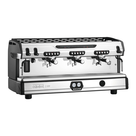
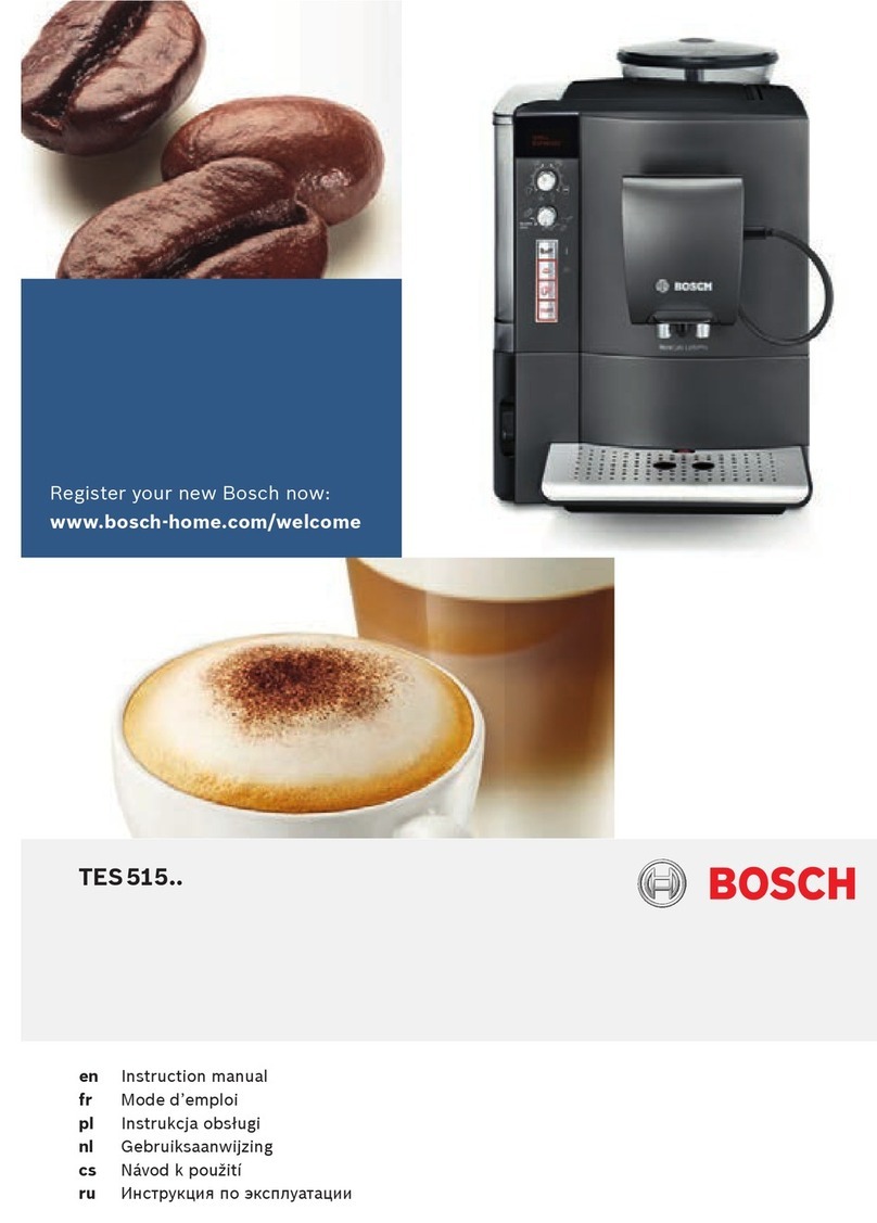
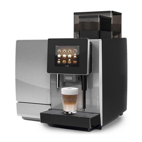
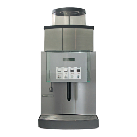
Franke T 200 User manual

T 200
Original Manual for Use and Maintenance
Read the operating instructions and the chapter
on safety information before operating the machine. Keep the
operating instructions near the machine.

II
11-03-2014 / LSC 044 / Rev. 00
WEEE
Disposal of the equipment by the users within the European Community ( WEEE) in compliance with the article 13 of the legislative decree is-
sued on 25 July 2005, nr151 ”Implementation of the directives 2002/95/CE,2002/96/CE e 2003/108/CE, concerning the decrease in the usage of
dangerous substances in the electrical and electronic equipment and the disposal of waste”.
The symbol of the crossed waste bin indicated on the equipment or on the packaging means that the product at the end of its lifetime must
be disposed of separately from all the other waste.
The separate collection of this equipment coming at the end of its lifetime is organized and run by the importer/distributor. The user who
should have to dispose of such equipment should get in touch with the importer/ distributor and follow the procedure they have adopted for
the separate disposal of the equipment coming at the end of its lifetime. The proper separate disposal of disused equipment so that it can
be recycled and treated according what is environmentally compatible contributes to avoid possible negative effects on the Environment and
on Health and allows the reutilization and/or the recycling of the materials the equipment is composed of.
The improper disposal by the user causes the enforcement of the administrative sanctions according to current regulations.

1
11-03-2014 / LSC 044 / Rev. 00
INDEX
1 GENERAL DESCRIPTION OF THE MACHINE ................................. 3
1.1 DESCRIPTION OF DELIVERY COFFEE TOUCHPAD................... 4
2. GENERAL ADVICE FOR THE INSTALLER ....................................... 5
2.1 GENERAL WARNINGS................................................................. 5
2.2 INSTALLATION REQUIREMENTS FOR THE USER...................... 7
2.3 WARNING/TECHNICAL DATA LABELS AND NAMEPLATES .........
APPLIED TO THE MACHINE........................................................ 9
3. REMOVING THE PACKAGING ....................................................... 10
3.1 STANDARD EQUIPMENT OF THE MACHINE............................ 10
3.2 OPTIONAL ACCESSORIES
(SUPPLIED ONLy ON REQUEST OF THE CUSTOMER)
................................... 11
4. COMMISSIONING THE MACHINE ................................................. 11
5. SWITCHING ON THE MACHINE .................................................... 12
5.1 COFFEE PREPARATION ............................................................ 13
5.2 EK MODEL ALARMS OPERATION............................................. 16
6 ROUTINE APPLIANCE MAINTENANCE
TO BE PERFORMED BY THE USER .............................................. 17
7 TECHNICAL DATA........................................................................... 19

2
11-03-2014 / LSC 044 / Rev. 00

3
11-03-2014 / LSC 044 / Rev. 00
1 GENERAL DESCRIPTION OF THE MACHINE
LEGEND
1. Top cup grid
2. Steam tap
3. Touchpad
4. Hot water tap
5. 2-cup filter holder
6. Steam wand
7. Drip tray grid
8. Water drip tray
9. Main on/off switch
10. Adjustable foot
11. Opening for gas burner inspection
12. Gauge
13. 1-cup filter holder
14. Hot water spout
15. Control knob for gas delivery (optional)
16. Piezoelectric lighter for gas (optional)
17. Electric cup warmer button (optional)
Fig. 1
43
1 2 2
3
6
15
16
13
14
10
17
9
8
7
6
5
1211

4
11-03-2014 / LSC 044 / Rev. 00
1.1 DESCRIPTION OF DELIVERY COFFEE TOUCHPAD
LEGEND
a. 1 short coffee preset delivery button
b. 1 long coffee preset delivery button
c. 2 short coffees preset delivery button
d. 2 long coffees preset delivery button
e. Continuous delivery key
Fig. 2
Touchpad model EK
ab
c e d

5
11-03-2014 / LSC 044 / Rev. 00
2. GENERAL ADVICE FOR THE INSTALLER
Read carefully the instructions and warnings contained in this manual and in the “INSTRUCTION MANUAL FOR THE INSTALLER”,
since they provide important indications concerning the installation of the appliance.
Attention!
The electric system, water supply system, drainage system and gas system (in case the appliance is pre-fitted for gas), MUST
already be put in place by the customer in order to allow the proper installation of the machine. The installation engineer cannot
change the existing system put in place by the customer. See chapter 2.2: “Installation requirements for the user”.
Attention!
The appliance must be installed where use and maintenance are restricted to trained staff.
Attention!
CAREFULLY READ THE FOLLOWING WARNINGS, WHICH OFFER IMPORTANT GUIDELINES FOR THE SAFE USE AND
MAINTENANCE OF THE APPLIANCE.
The appliance must only be used for its intended purpose and it must be installed in a suitable place for its use. Any other use is there-
fore considered as improper and unreasonable.
The manufacturer cannot be held liable for any damage caused by improper, incorrect or unreasonable use. Installation must be carried
out by qualified personnel according to current laws and to the manufacturer’s instructions. Incorrect installation may cause damage to
people, animals or property for which the manufacturer cannot be held liable.
2.1 GENERAL WARNINGS

6
11-03-2014 / LSC 044 / Rev. 00
Danger!
The electrical safety of the appliance is fully achieved only after it has been correctly connected to an earthing system as
required by the laws in force.
It is necessary to have the earthing connection checked by professionally qualified personnel. The manufacturer cannot be held liable
for any damage caused by the lack or inefficiency of the system’s earthing connection. The appliance has not been designed for outdoor
use. It must only be operated in a place where the ambient temperature is between
+5°C
and
+40°C
.
Attention!
The use of any electrical appliance also requires observance of the following important regulations.
• Donottouchtheappliancewithwetordamphandsorfeet.
• Donotusetheappliancebarefooted.
• Donotpullthepowersupplycordtounplugtheappliancefromthemainspower.
• Donotallowchildrenorunqualifiedpersonstousetheappliance.
• Accesstotheappliance’sserviceareamustberestrictedtothosepersonswiththerelevantpracticalexperienceandfamiliaritywith
the appliance itself, especially in terms of safety and hygiene.
• Thedeviceisnotintendtobeusedbypeople(childrenincluded)whosephysical,sensoryormentalcapabilityarereduced,unless
they could benefit, through the intermediation of a person in charge of their safety, of a guard or of instructions concerning the de-
vice’s use. Children must be kept under surveillance to be sure they wouldn’t play with the device.
• Beforecarryingoutanyroutinemaintenanceorcleaningoperation,disconnecttheappliancefromthemainspowerandshutoffthe
water supply tap.
• Intheeventofdamageand/ormalfunctionoftheappliance,switchitoffcompletelywithouttryingtomakeanydirectrepairs.Contact
the nearest Service Centre authorised by the manufacturer.
• Inordertoguaranteetheproperefficiencyandoperationoftheappliance,itisfundamentallyimportanttofollowthemanufacturer’s
instructions, and to follow a regular maintenance schedule.
• TheappliancehasIPX2 protection against water and therefore, it cannot be installed in areas where it may be subject to jets of water.
7
11-03-2014 / LSC 044 / Rev. 00
• Theappliancehasclass I protection against electric shocks.
• Thenoiseemittedbytheapplianceduringnormaloperationislessthan70 dB.
• NOTE:Appliancefittedtooperatewithgassystem.TheappliancehasbeenfittedbythemanufacturertooperatewithLPG under a
maximum supply pressure of 30 mbar. Adaptation to operate with any other type of gas must be carried out by personnel authorised
by the manufacturer.
Attention!
Failure to comply with the above regulations could jeopardise the correct operation and safety of the appliance as well as its
useful lifetime.
2.2 INSTALLATION REQUIREMENTS FOR THE USER
The appliance must be placed on a flat and stable surface and a
surface height for the appliance of no less than 1.2 metres from
the ground. Check this important requirement, since the manu-
facturer cannot be considered liable for any damage caused by
the instability of the appliance. While preparing the system, take
into account that a hole is needed in the bearing surface in order
to make all electric and water connections through the opening
below where a water softener will need to be fitted, if recom-
mended by the installation engineer.
A hole of
10 x 10 cm
is enough in the area (a) as indicated in
Pict. 3.
The machine needs a minimum clearance of:
- height 60 cm.
- width 40 cm.
- depth 40 cm.
Y
XX
A
2
13
4
Fig. 3
Legend:
1Single pole switch
with an opening of at
least 3 mm between
contacts.
2Water supply tap
3Drain siphon
4Gas supply tap (if fit-
ted)
Xmin. 20 cm.
Ymin. 40 cm.
Z* min. 10 cm.
*) Distance between the
back of the appliance
and the wall.

8
11-03-2014 / LSC 044 / Rev. 00
• Betweenthewatermainsandthewaterinletpipeoftheappliance,theremustbeataptostopthewaterflowifnecessary
(2 -
Pict
.3).
• Thewatermainspressuremustbewithintherangeof1 and 6 bar.
• Ifthisrequirementisnotmet,pleaseconsultthemanufacturer.
• Theapplianceissuppliedwithoutaplug.Itissupposedtobedirectlyconnectedtotheelectricmainsandtherefore,itisnecessary
to fit a single-pole switch with contact opening of 3 mm or more beforehand, according to the regulations in force
(1 -
Pict
.3).
• Thedrainpipeoftheappliancemustbedirectlyconnectedtoasuitableopendrainsiphon,previouslyinstalledbythecustomer(3
- Pict.3). Do not fit the drain pipe into basins or buckets placed under the counter as this will increase the possibility of forming dirt
deposits and as a result, the spread of bacteria
.
Attention!
The appliance is supplied without water in the boiler. This is to prevent serious damage if the appliance is exposed to low
temperatures. The appliance must only be supplied with cold drinking water.
Attention!
For appliances operating with gas, the gas supply tap must be fitted in an easily accessible place (4 - Pict. 3), so as to be able
to shut off the gas supply if necessary.
Regularly check the expiry date on the gas pipe connecting the system and the appliance and have it replaced by the Service
Centre before this date.

9
11-03-2014 / LSC 044 / Rev. 00
2.3 WARNING/TECHNICAL DATA LABELS AND NAMEPLATES APPLIED TO THE MACHINE
In the figure below are shown the warning/technical data labels and nameplates positioned on the machine.
Warning!
Dedicate the time necessary to familiarise yourself with these labels.
Ensure that they are readable and keep them clean or replace those that have deteriorated or illegible (both the text and the
graphics).
Use a soft cloth, soap and water to clean the labels. Do not use solvents, petrol, etc..
If a label is positioned on a component part that has to be replaced, ensure that the new component has the same label ap-
plied or a new one.
N.F. 255600
La Spaziale S.p.A.
Macchine per caffè espresso
via E. Duse, 8
40033 Casalecchio di Reno BOLOGNA
N.F.
SERIE: - MOD.
VOLT SN~ Hz
WATT IPX2
- MADE IN ITALY -
( UCIMAC )
CALDAIA: L. MPa
PS 0.6 MPa MAX
Fig. 4

10
11-03-2014 / LSC 044 / Rev. 00
3. REMOVING THE PACKAGING
After unpacking the machine, please check its integrity; in case of doubt, do not use it and consult the manufacturer.
Packaging materials must not be left within children’s reach since they are potentially dangerous.
Attention!
The appliance weight is more than 30 kg and therefore, it cannot be moved by a single person alone.
Take note!
Dispose of the packaging as per the norms in force of the country in which the machine is utilised.
3.1 STANDARD EQUIPMENT OF THE MACHINE
LEGEND
A. 1 set of filter holders with relative spouts
B. 1 complete set of hoses for connection to water mains
C. 2 sets of filters
D. 1 set of shower heads
E. 1 wrench for shower head removal
F. 1 brush
G. 1 blind filter
H. 1 manual coffee tamper
I. 1 set group-head gasket

11
11-03-2014 / LSC 044 / Rev. 00
3.2 OPTIONAL ACCESSORIES
(Supplied only at the request of the customer)
LEGEND
I. Water softener
L. Filter
M. Pressure reducer
N. Detergent
4. COMMISSIONING THE MACHINE
a) Open the water supply valve as envisaged in the preparations for installation (See Pict. 3 on page 7 - Rif. 2).
b) Check for any water leaks from the hosing/connections.
c) Switch on the main breaker as envisaged in the preparations for installation (See Pict. 3 on page 7 - Rif. 1)

12
11-03-2014 / LSC 044 / Rev. 00
5. SWITCHING ON THE MACHINE
FILLING THE BOILER
A. Turn the knob of the switch on the appliance (9) to 1; at this point the LEDs on the touchpads will switch on to indicate that power
is feeding the machine.
B. Water will now automatically fill the boiler as far as the level set by the manufacturer.
ONLY FOR EQUIPMENT FITTED TO OPERATE WITH GAS (Optional)
A. Open the gas tap mentioned in the preparation of the system (pict. 3 - page 7).
B. Turn the knob (15) on the machine by 90° until the symbol of the large flame on the knob itself is at the top.
C. Push the knob (15) and the gas igniter (16) at the same time until the gas turns on; this can be seen through the inspection opening
(11).
D. Hold down the knob (15) for about 10 seconds and check through the special inspection opening (11), that the flame stays lit.
E. It is recommended to turn the gas adjustment knob (15) to the small flame setting during summer to prevent useless overheating of
the coffee cups on the top grid of the machine (1).
APPLIANCE HEATING AND PREPARATION STAGE
A. Once the boiler has been filled, turn the dial on the switch to position 2 (power to the boiler heating element).
B. Fasten the filter holders (5) to the delivery groups (13).
C. Open the steam valves (2) (by moving the levers upwards) and leave them open; then move the steam wands (6) over the grid (7).
D. Wait for steam to come out from the wands (6), then close the steam valves (2) (by moving the levers downwards).
E. Wait for the appliance to reach operating temperature, which can be seen on the pressure gauge (12) on the appliance.
The boiler’s pressure is normally set by the manufacturer to 1 bar.
F. The appliance is ready for use.

13
11-03-2014 / LSC 044 / Rev. 00
Take note!
The running temperature is the temperature of the boiler during normal operation.
5.1 COFFEE PREPARATION
A.
Remove a filter holder
(5 or 13 a
according to whether 1 or 2 cups of coffee are required
)
from the
delivery
group
.
B. Fill with ground coffee, taking care not to leave any coffee powder residues on the top edge of the filter holder, then press it using
the special coffee press supplied.
C. Re-insert the filter holder firmly.
D. Place one or two cups below the filter holder (5 or 13 a
according to whether 1 or 2 cups of coffee are required
).
Take note!
To stop coffee delivery earlier after using one of the buttons with pre-set doses, just press the button on the same touchpad.

14
11-03-2014 / LSC 044 / Rev. 00
POURING HOT WATER FOR PREPARING INFUSIONS
A. Place the pitcher underneath the hot water spout.
B. Moving the levers upwards (4) in order to obtain the required amount of water.
C. Close the tap to stop delivering water by setting the lever (4) to its initial position.
Attention!
Do not use the lever to deliver hot water before placing the pitcher below the hot water spout, to prevent possible burns.
DELIVERY STEAM FOR HOT DRINK PREPARATION
A. Insert the steam wand (6) into the pitcher containing the drink to be heated up.
B. Open the tap of the corresponding steam by moving the lever (2) upwards.
C. Once the heating phase is finished, stop delivering steam by moving the levers (2) downwards, remove the steam wand from the
pitcher and clean it immediately with a wet sponge, removing all residues of the heated drink.
Attention!
Do not close the taps (2) to deliver steam before inserting the steam wand (6) into the pitcher in order to prevent possible burns.

15
11-03-2014 / LSC 044 / Rev. 00
15
ELECTRIC CUP WARMER (Optional)
The appliances can also be equipped with an electric cup warmer (as optional) for an
additional cup heating. To switch on the cup warmer, press the button (17).
Press the same button to switch it off.
Attention!
It is allowed to place cups on the special cup grid (1) on the top of the appli-
ance as long as the cups have their openings facing upwards (pict. 5). This is
in order to prevent that the combustion fumes of the gas burner, on machines
fitted with gas system may come into contact with the inside of the cups, which
are supposed to contain coffee.
Fig. 5

16
11-03-2014 / LSC 044 / Rev. 00
5.2 EK MODEL ALARMS OPERATION
LED CORRESPONDING TO THE COFFEE DOSE BUTTON DISPENSING, FLASHING AFTER 5-6 SECONDS:
This alarm is viewed when, during the delivery phase, there is a flow meter malfunction for the delivery group, or if the coffee has been
too finely ground. After checking the grinding fineness, if the problem continues, contact an authorised Service Centre.
ALL LEDS CORRESPONDING TO ALL DOSES ON ALL TOUCHPADS FLASHING:
The automatic filling function for the boiler tank has been operating for more than 4 minutes (6 minutes for the 3 groups version), total
machine block. To return to the standard operating phase, switch the machine off using the main ON/OF switch.
If this problem is repeated frequently, contact an authorised Assistance Centre.

17
11-03-2014 / LSC 044 / Rev. 00
6 ROUTINE APPLIANCE MAINTENANCE TO BE PERFORMED BY THE USER
Take note!
To grant the efficiency of the appliance and to maintain correct operation, it is necessary to follow the manufacturer’s instruc-
tions as to cleaning and regular maintenance.
Attention!
Cleaning and routine maintenance operations must be carried out by the user according to the manufacturer’s instructions
givenherebelow.Beforecarryingoutanykindofcleaningoperation,disconnecttheappliancefromtheelectricitymainsand
from the gas system (if fitted). Cleaning and routine maintenance operations must be carried out when the machine is cold and
using protective gloves to prevent abrasions.
DAILY AT THE END OF THE JOB
1) Replacing the water in the boiler.
After turning off the appliance, replace the water in the boiler as follows:
•Placeacontainerthatcanwithstandhightemperaturesbelowthehotwaternozzle(14)topreventanyhotwaterspills.
•Keepopenthehotwatertap(4)untiltheboileriscompletelyempty;switchthemachineonagainandthecorrectwaterlevelfor
the boiler will automatically be restored.
2) Then clean the filter holders and the filters with the brush provided, making sure no dirt is left inside the filter holders and that all filter
holes are clean.
3) Clean the shower heads below the delivery groups with the brush.
4) Clean the drip tray (8) and the cup grid (7), using the standard detergents on sale, if necessary.

18
11-03-2014 / LSC 044 / Rev. 00
18
Every 3 days
After turning off the machine, remove the shower heads using the wrench provided;
brush them carefully, making sure that all the holes are clean. Then reassemble the
parts following the sequence shown in the picture 6.
A. Fastening screw
B. Small shower head
C. Large shower head
D. Diffuser
E. Delivery group
E
D
B
C
AFig. 6
Take note!
Do not use water jets to clean the machine.
Attention!
Every day, at the end of work and after daily cleaning, turn off the appliance using the electric switch; then close the water supply tap
and the gas tap (see pict.3- page.7)
WATER SOFTENER
If the installation of a water softener has been recommended by the installation engineer because of hard water and problems of scale
deposits, it is necessary to follow the instructions of the water softener’s manufacturer (periodic regeneration).
BODYWORK
Clean the bodywork of the appliance using mild detergent to prevent any damage.
We recommend not to use abrasive sponges that could damage the body panels.
Table of contents
Other Franke Coffee Maker manuals

Franke
Franke S700 User manual

Franke
Franke EVOLUTION PLUS User manual

Franke
Franke bremer VIVA User manual

Franke
Franke Bremer VIVA KM Configuration guide

Franke
Franke Evolution User manual

Franke
Franke SINFONIA User manual

Franke
Franke Evolution User manual

Franke
Franke A400 User manual

Franke
Franke EVOLUTION PLUS User manual

Franke
Franke Spectra S User manual

Franke
Franke Ecolino User manual

Franke
Franke SB1200 FM CM User manual

Franke
Franke SU12 User manual

Franke
Franke SPECTRA X User manual

Franke
Franke Mythos FMY 45 CM XS User manual

Franke
Franke A800 User manual

Franke
Franke SB1200 Configuration guide

Franke
Franke MYTICO VARIO User manual

Franke
Franke Flair User manual

Franke
Franke A600 User manual