Fraser NEOS 30 OEM User manual

Fraser Anti-Static Techniques, Scotts Business Park, Bampton, Devon EX16 9DN, UK
1
NEOS 30 OEM-DM-Iss.2
NEW PRODUCT
NEOS 30 OEM - DISTRIBUTOR MANUAL
Section 1 - Product Information
1. Background
2. Key New Features
3. Typical Applications
4. Position in the NEOS range
5. Why is it called OEM?
6. Differences to standard NEOS 30
7. Performance
02
03
03
05
05
06
07
1. Introduction
2. Safety
3. Use
4. Checking on Delivered Equipment
5. General Specication and Dimensions
6. Positioning
7. Operation & Control
8. Mechanical
9. Maintenance
10. Certication and EU Declaration of Conformity
11. Troubleshooting
12. Spare Parts & Accessories
08
09
10
10
11
12
13
20
20
21
21
22
Section 2 - Technical & Installation
CONFIDENTIAL

Fraser Anti-Static Techniques, Scotts Business Park, Bampton, Devon EX16 9DN, UK
2
NEOS 30 OEM-DM-Iss.2
1. BACKGROUND
NEOS
The standard NEOS Bars have become accepted as the most effective static eliminators in their respective classes:
from NEOS 12, which is the most effective short range Bar available
to NEOS 30, which is the most powerful long range Bar available
Please refer to the comparison between the Simco ThunderION 2.0 and the NEOS 30 which was sent to you in February 2019. It
shows that the NEOS 30 is comprehensively better than the market leader at all distances.
Frequency and Long Range Static Neutralisation
It is useful to repeat these notes, as they are essential for understanding the benets of the NEOS 30 OEM and where it ts into the
NEOS range.
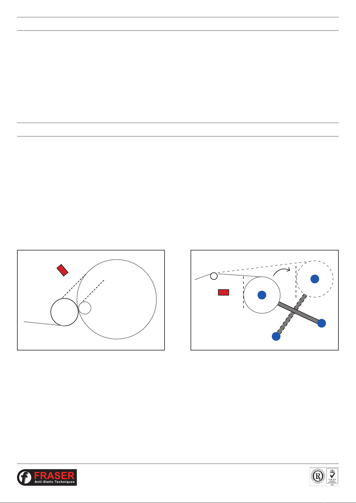
The method for neutralising at long distance without air assistance is to reduce the frequency of the ion emission so that it
produces bigger elds of ions which propel each other outwards. This is the basic operation for all pulsed DC static neutralisation.
Generally:
- short distances are neutralised with higher frequency – for example, 50 Hz on the 3014 and 3024F
- longer distances are neutralised with slower frequency – for example, 5 Hz on the 3024L
When NEOS Bars are used in intelligent operating modes (AN or AL) they respond to the polarity of the electric eld from the
object and change the wave pattern to output more ions of the opposite polarity. This effect also compensates to a large degree
for changes in distance within the sensing range. The unipolar elds in AN and AL modes can be larger and so act like slower
frequency elds.
In AL mode the NEOS 30 can sense a strong electric eld at distances up to about 750 mm. In this range there will effectively be
automatic compensation for distance.
If the electric eld is too weak, usually because the target is too far away, a Manual setting may produce better neutralisation. For
example, the NEOS 30 in setting M1 (0.5 Hz) neutralises at distances over 750 mm more efciently than in AL mode.
What if the object to be neutralised moves from a short distance to a distance over 750 mm?
For example, from 200 mm to over 1m?
The NEOS 30 OEM has been developed to deal with this problem.
SECTION 1 - PRODUCT INFORMATION

Fraser Anti-Static Techniques, Scotts Business Park, Bampton, Devon EX16 9DN, UK
3
NEOS 30 OEM-DM-Iss.2
2. KEY NEW FEATURES
The essential and unique feature of a NEOS 30 OEM Bar is that it receives a signal from the PLC of the machine which indicates the
distance between the charged material and the Bar. This tells the NEOS 30 OEM to adjust the frequency to the optimal setting for
that distance.
In this way the output frequency of the Bar is directly controlled by the PLC of the production machine without the need for
additional sensors.
It results in the best possible static neutralisation for difcult applications.
3. TYPICAL APPLICATIONS
NEOS 30 OEM has been developed for dynamic applications where the distance between the charged material and the Bar
changes signicantly during the manufacturing process.
A large part of this market will be where winders and unwinders are used. High productivity, modern machinery in the converting,
plastic, paper and related industries is designed to handle bigger reels of material, often with automated changeover.
This means that the distance between the static eliminator and the material can vary over a large range. This is where the NEOS 30
OEM has unrivalled advantages.
Typical Examples:
Winders:
A
B
Lay-on Roller
At the start of the wind, position A, the material is over 1 m
from the NEOS 30 Bar.
At the end of the wind, position B, the material is 200 mm
from the NEOS 30 Bar.
The NEOS 30 OEM can automatically change frequency to
cope with this change in distance.
Turret Rewinder
If the reel stays in a farther position before changeover for a
signicant period of time, then a NEOS 30 OEM will be able
to neutralise the reel in both positions.

Fraser Anti-Static Techniques, Scotts Business Park, Bampton, Devon EX16 9DN, UK
4
NEOS 30 OEM-DM-Iss.2
3. TYPICAL APPLICATIONS
Unwinders:
Winders and unwinders are found on hundreds of different types of production machinery.
Unwinder
The NEOS Bar is 200 mm from the surface of a new reel, but the
core is over 1 m away.
Usually the static charge becomes more severe as the reel
reduces in size. It is important that the ionisation reaches the reel
when it is small.

Fraser Anti-Static Techniques, Scotts Business Park, Bampton, Devon EX16 9DN, UK
5
NEOS 30 OEM-DM-Iss.2
4. WHERE DOES NEOS 30 OEM FIT INTO THE NEOS RANGE?
NEOS 30 OEM does not replace the existing NEOS 30 Bar, but provides a powerful new ionisation system to cope with the difcult
applications where the target distance changes substantially.
It is a long range static eliminator which can automatically adjust its ionised output to provide optimal performance at distances
varying from 200 mm to 1500 mm.
The standard NEOS 30 has settings for most industrial requirements (see NEOS Distributor Manual):
The NEOS 30 OEM can be used for all of these distance ranges. Please see Performance section for more details.
NEOS 30 SETTING FOR DISTANCES
AN 200 mm - 500 mm
AL 300 mm - 750 mm
M3 200 mm - 500 mm
M2 300 mm - 750 mm
M1 500 mm - 1000 mm
NEOS 30 OEM 200 mm - 1500 mm
5. WHY IS IT CALLED OEM?
It is called OEM because it has been developed for, and with the assistance of, OEMs and we see that its main market will be with
machinery manufacturers.
We can customise the output to meet the special requirements of each type of OEM machine. For example, if a machine has a
requirement for neutralisation at a distance from 500 mm to 1300 mm, we can optimise the ionisation for this distance range.
This gives our distributors and sales teams a great opportunity to work closely with OEMs and offer them unique benets for
their machines.

Fraser Anti-Static Techniques, Scotts Business Park, Bampton, Devon EX16 9DN, UK
6
NEOS 30 OEM-DM-Iss.2
6. WHAT ARE THE DIFFERENCES BETWEEN NEOS 30 OEM AND STANDARD NEOS 30?
Visually, the only differences are on the cable endcap:
• there are two connector sockets: the normal NEOS 30 M12 x 5 pin and an additional M8 x 3 pin which receives the signal from
the machine’s PLC.
• the selector dial for Automatic and Manual modes is not required for the NEOS 30 OEM.
• the LED is the same. It shows green for ‘all OK’, red for ‘fault’ and green/red for ‘clean me’. When green, it ashes to show the
operating frequency.
In all other ways the NEOS 30 OEM is externally the same as the standard NEOS 30:
• same compact prole (half the size of the Simco ThunderION)
• same lengths available: 600 mm, 750 mm then in 250 mm steps to 5 m
• same xings for installation
• same market-leading, replaceable tungsten emitters
Electrically, the OEM model incorporates a wiring improvement which will eventually be used in all NEOS Bars. We have eliminated
the requirement for external pull-up resistors, which makes electrical installation much easier for the customer.
Please see section 7.3 of Operating Instructions in Section 2 of this manual.
Performance differences - see next section Performance.
The endcap of the NEOS 30 OEM.
With an additional M8 x 3 pin connector
for the signal from the machine’s PLC.
With the same M12 x 5 pin connector.

Fraser Anti-Static Techniques, Scotts Business Park, Bampton, Devon EX16 9DN, UK
7
NEOS 30 OEM-DM-Iss.2
7. PERFORMANCE
How does NEOS 30 OEM Compare to the Manual NEOS Settings?
The NEOS 30 OEM has slightly better performance to the M1, M2 and M3 manual settings on the standard NEOS 30.
This is because, although the frequencies may be similar, the NEOS 30 OEM changes gradually, not in steps of 0.5 Hz, 1.0 Hz, 1.5 Hz
etc. This ne tunes the performance for maximum efciency as the distance changes.
The big difference, though, is that it changes automatically between these settings according to the distance signal from the PLC.
In this way it is always at its most powerful manual setting for the job.
The operator does not have to change the setting between different jobs to ensure optimal performance.
How does the performance of NEOS 30 OEM compare to the ‘intelligent’ AN and AL Settings?
This is more difcult to answer because the effectiveness of the AL and AN setting depends on the size of the charge – the bigger
the charge, the better the sensing.
We compared the performance of the NEOS 30 OEM and the standard ‘intelligent’ settings on our constant current charge plate
monitor. We used a plate voltage of 25 kV to represent a typical charge and used distances from 200 mm to 1.5 mm. The results
were:
• AN setting was better than NEOS 30 OEM at distances up to 470 mm
• AL setting was better at distances up to 625 mm
These results will vary with the size of the charge. However, the tests make it clear that at longer ranges, the NEOS 30 OEM will
give a better overall result.
Please remember that we can customise the performance to meet the particular requirements of the machine. The default setting
is for distances from 200 mm to 1500 mm. We can change this to meet the OEM`s machinery, for example:
If the distance changes from:
or
or
700 mm to 1500 mm
1100 mm to 500 mm
300 mm to 1400 mm to 300 mm

Fraser Anti-Static Techniques, Scotts Business Park, Bampton, Devon EX16 9DN, UK
8
NEOS 30 OEM-DM-Iss.2
1. INTRODUCTION
This manual applies to the NEOS 30 OEM Static Eliminator Bar supplied from December 2018.
It is essential that you read and understand the complete manual before installing and using this equipment. This is important for
safety and for warranty cover.
SECTION 2 - TECHNICAL & INSTALLATION
1.1 Explanation of Symbols
Warning!
This symbol appearing in the operating instructions refers to operations which, if carried out
improperly, may result in serious personal injuries.
Caution!
This symbol appearing in the operating instructions refers to operations which, if carried out
improperly, may result in damage to property.

Fraser Anti-Static Techniques, Scotts Business Park, Bampton, Devon EX16 9DN, UK
9
NEOS 30 OEM-DM-Iss.2
2. SAFETY
Warnings:
- The Anti-Static Bar is only designed for neutralising surfaces with an electrostatic charge.
- Electrical installation must only be carried out by suitably qualied personnel.
- Adequate installation earth / ground is required to ensure safe and proper operation.
- The 0 V return of the 24 V DC electrical supply must be earthed.
- Disconnect the power supply before cleaning or handling the Bar.
- The emitters are sharp and can cause physical injury.
- There are no user serviceable parts inside the Bar.
- Ensure the Bar and connecting cable are free from damage prior to installation and check periodically once in use.
- Bar must be switched off before removing or reconnecting the signal cable.
- A small amount of ozone will be produced as part of the ionisation process. When installed correctly the level of concentration
of ozone is less than 0.1 ppm and is within internationally accepted limits.
Any changes to the equipment without written consent of the manufacturer will nullify the warranty and CE certication.
As with all pulsed DC static eliminators, it is possible for the user to receive a small static shock as a result of
their body being charged by the bar, and then discharging to a nearby earthed object. This is not dangerous,
but may be uncomfortable and cause surprise. It is for this reason that the signal cable must not be removed or
reconnected when the bar is powered.

Fraser Anti-Static Techniques, Scotts Business Park, Bampton, Devon EX16 9DN, UK
10
NEOS 30 OEM-DM-Iss.2
3. USE
The NEOS 30 OEM is a long range static eliminator designed to neutralise electrostatically charged surfaces at distances between
200mm and 1500mm. A signal on the 4-20mA current loop input allows the bar frequency to be varied as distance to the charged
material varies, such that optimal electrostatic neutralisation can occur.
Powered by 24 V DC with integrated HV supplies and remote monitoring to check bar function remotely. Connection to 24 V DC is
via a standard M12 5-Pin Connector. Connection to 4-20mA current loop signal is via a standard M8 3-Pin connector.
Not suitable for outdoor use.
4. CHECKING ON DELIVERED EQUIPMENT
The equipment leaves our factory in suitable protective packaging. Please check that it is undamaged when it arrives. If there is
visible damage contact the Factory or one of our Distributors immediately, before carrying out any installation.
Check that the parts which have been delivered are the same as you have ordered.
Loose Parts: Mounting ‘T’ pieces and xings - two for the lengths up to 1m plus
one extra mounting bracket for every additional 500 mm.
NEOS 30 OEM: Emitter Key and two spare emitters.
M12 5-Pin Connector and lead(s) or Power Supply Unit - as per order.

Fraser Anti-Static Techniques, Scotts Business Park, Bampton, Devon EX16 9DN, UK
11
NEOS 30 OEM-DM-Iss.2
5. GENERAL SPECIFICATION AND DIMENSIONS
Power Supply:
Voltage: 24 V DC (21-27 V).
Current: NEOS 30 OEM 2.5 A DC Max.
Connection: M12 5-Pin. A-coded.
High Voltage: NEOS 30 OEM - 30 kV integrated into Bar.
Supply Cable: Low voltage, industry standard M12 5-Pin female connector.
Emitters: Long life, high grade Tungsten.
LED Green/Green Flashing = OK
Flashing Red = Standby
Red = Fault
Red/Green Flashing = Attention required
Status Indication:
OK/Attention Open-Collector outputs with internal 1k5 pull-up resistor.
Remote DISABLE input.
Signalling:
Environmental:
IP67. Internal use.
0-55 °C Max.
Dry: max 70% RH, non condensing.
Length: NEOS 30 OEM available at 600 mm, then 750 mm to 5000 mm in 250 mm steps.
Weight: NEOS 30 OEM - 3.6 kg/m.
Mounting: M6 x 40 mm Fixing slides and Flange Nut.
Approvals: CE, UL and CB.
*Note – overall length = order length + 7mm (including end cap)
33.6
76

Fraser Anti-Static Techniques, Scotts Business Park, Bampton, Devon EX16 9DN, UK
12
NEOS 30 OEM-DM-Iss.2
6. POSITIONING
The best location is at, or immediately before, the area where static is causing the problem. Remember that
static can be regenerated if the material passes over rollers or through a process after neutralising. A Static
Meter is useful to determine the best position.
i.
Important: Except on a winding reel of material, the material to be neutralised should be in free air, not
touching another surface as it passes the Bar. It is not possible to neutralise static electricity where the
material is touching another surface or roller.
ii.
The Bars must be dry and oil-free.iii.
It is important that the emitter pins are not touching, or close to metal objects, to avoid spark erosion that
will damage both the Bar and the metal object.
iv.
The distance from the material should be:
NEOS 30 OEM: 200 - 1500 mm
v.
1.0
R60.0 MIN DISTANCE FROM
ANY EARTHED OBJECTS OR METAL
PLASTIC
PERFORMANCE LEVEL
NEOS 12 F
PERFORMANCE LEVEL
NEOS 12 L
MATERIAL MATERIAL
FREE AIR
MATERIAL
NO OBJECTS IN THIS AREA
x
x
x
x
MATERIAL
FREE AIR
MATERIAL
R = min. 300 mm
Area to be free of all
ground references
1.0
R60.0 MIN DISTANCE FROM
ANY EARTHED OBJECTS OR METAL
PLASTIC
PERFORMANCE LEVEL
NEOS 12 F
PERFORMANCE LEVEL
NEOS 12 L
MATERIAL MATERIAL
FREE AIR
MATERIAL
NO OBJECTS IN THIS AREA
x
x
x
x

Fraser Anti-Static Techniques, Scotts Business Park, Bampton, Devon EX16 9DN, UK
13
NEOS 30 OEM-DM-Iss.2
7. OPERATION & CONTROL
The pin assignment and typical wire colours are given in the table below:
MALE
PIN
VIEW
1 3
2
ON
BAR
FEMALE
SOCKET
VIEW
3 1
2
ON
CABLE
Pin Wire Colour Function Details
1
2*
3
Brown
Black
Blue
I in
I out
0 V + GND
Current loop input (+)
Current loop output (-)
0 V / GND, connected internally to power supply 0 V
*Pin 2 numbered pin 4 by some cable suppliers.

Fraser Anti-Static Techniques, Scotts Business Park, Bampton, Devon EX16 9DN, UK
14
NEOS 30 OEM-DM-Iss.2
7. OPERATION & CONTROL
Electrical:
Using an existing 24 V DC supply the 24 V return must be tted with:
2.5 Amp fuse e.g. Type : 2.5 AT 250 V.
The 0 V output must be connected to earth.
+
-
DC
Fuse
+24V
0V
AC
AC
GND
FEMALE SOCKET
21
4
5
3
MALE PLUG
12
3
5
4
Pin Wire Colour Function
1
2
3
Brown
White
Blue
24 V
OK
0 V & Earth
4 Black Attention
5 Grey or Green / Yellow Disable

Fraser Anti-Static Techniques, Scotts Business Park, Bampton, Devon EX16 9DN, UK
15
NEOS 30 OEM-DM-Iss.2
7. OPERATION & CONTROL
Signalling:
The NEOS Bars feature two open-collector outputs to enable remote monitoring of Bar status, and a logic-level DISABLE input
to allow the HV supplies to be externally disabled when not required (“Standby” mode). For example, the bar can be linked into a
machine’s safety interlock system to ensure operator safety during changeover periods.
See wiring diagram and examples below.
Open-collector outputs (OK, ATTENTION)
Both open-collector outputs are capable of sinking a current of up to 200 mA, allowing direct driving of external lamps or relays, or
an external LED with a suitable current limiting resistor. An internal 1k5 pull-up resistor provides a 24V signal suitable for driving a
24V PLC digital input compatible with IEC 61131-2 ‘Type 1’ or ‘Type 3’. See wiring diagram and examples in the next section.
Both output signals are active low, meaning that a signal is asserted by a connection to 0 V via a low-powered solid-state switch.
The two signals are valid 5 seconds after power is applied, according to the following conditions:
Condition Ionisation OK (White, Pin 2) Attention (Black, Pin 4)
Bar powered, all OK ACTIVE (HV ON) ACTIVE (connected to 0 V) ACTIVE (connected to 0 V)
Bar powered, requires
attention (e.g. cleaning) ACTIVE (HV ON) ACTIVE (connected to 0 V) INACTIVE (open-circuit)
Bar not powered, overload
or hardware fault INACTIVE (HV OFF) INACTIVE (open-circuit) INACTIVE (open-circuit)
Standby mode INACTIVE (HV OFF) INACTIVE (open-circuit) ACTIVE (connected to 0 V)
A working Bar in good operating condition will thus internally connect both opencollector outputs to 0 V,
after a delay of up to 5 seconds after power is applied. Voltage applied to open collector outputs must not
exceed 28 V DC, and must be of the correct polarity.
The current through the open collector switch must not exceed 200 mA. Failure to limit the current into the
open collector outputs may cause permanent damage to the product. Do not connect the open collector
outputs directly to 24 V.
D
TITLE
REVISION
MATERIAL
SCALE
DRAWING No.
5 6
C
DO NOT SCALE
SHEET 1 OF 1
B
A
123
C
IF IN DOUBT - ASK
4 5
B
6
A
D
1 2
THIRD
ANGLE
3
PROJECTION
ALL SHARP EDGES AND CORNERS TO BE REMOVED
MACHINING TOLERANCES UNLESS OTHERWISE STATED
4
SPECIFICATION AND SYMBOLS TO BS308
ONE DECIMAL PLACE
TWO DECIMAL PLACES
0-100mm
100-500mm
ABOVE 500mm
SURFACE FINISHES TO BS1134
±0.1mm
±0.01mm
±0.25mm
±0.4mm
±0.75mm
A3
SCOTTS BUSINESS PARK
BAMPTON, DEVON
EX16 9DN
WWW.FRASER-ANTISTATIC.COM
TEL: 44-(0) 1398 331114
FAX: 44-(0) 1398 331411
1:5

Fraser Anti-Static Techniques, Scotts Business Park, Bampton, Devon EX16 9DN, UK
16
NEOS 30 OEM-DM-Iss.2
7. OPERATION & CONTROL
Example applications of open-collector outputs:
External lamp/indicator
External lamps or indicators can be connected to the OK or ATTENTION outputs to remotely display Bar status. This is useful for
bars mounted in inaccessible areas. Lamp rating 24 V DC, maximum 5 W. A LED can also be used with a suitable resistor. Maximum
lamp current 200 mA.
External relay
An external relay can be connected for additional control/feedback applications. Coil rating 24 V 5 W max.
External PLC ‘Type 1’ or ‘Type 3’
Interfacing to an external 24V IEC 61131-2 ‘Type 1’ or ‘Type 3’ PLC digital input can be achieved by direct connection.
O
DETAIL O
BROWN = +24V DC
WHITE = OK
BLACK = ATTENTION
GREY or
GREEN / = ON/OFF
YELLOW
BLUE = 0V / GROUND
LAMP
BLACK /ATTN
BROWN WIRE
MAX 200mA
+24V
WHITE /OK
NEOS INTERNAL
M12 CONNECTOR
BLUE = 0V / GROUND
GREY or
GREEN / = ON/OFF
YELLOW
BLACK = ATTENTION
WHITE = OK
BROWN = +24V DC
4
2
RELAY 24V
WHITE WIRE
BROWN WIRE
MAX 200mA
+24V
RELAY 24V
BLACK WIRE
BROWN WIRE
MAX 200mA
+24V
BLACK WIRE
WHITE WIRE
PLC
1
42
RELAY 24V
WHITE WIRE
BROWN WIRE
MAX 200mA
+24V
RELAY 24V
BLACK WIRE
BLACK WIRE
WHITE WIRE
PLC
2
4
OK
ATTENTION
MAX 200m A
D
TITLE
REVISION
MATERIAL
SCALE
DRAWING No.
5 6
C
DO NOT SCALE
SHEET 1 OF 1
B
A
123
C
IF IN DOUBT - ASK
4 5
B
6
A
D
1 2
THIRD
ANGLE
3
PROJECTION
ALL SHARP EDGES AND CORNERS TO BE REMOVED
MACHINING TOLERANCES UNLESS OTHERWISE STATED
4
SPECIFICATION AND SYMBOLS TO BS308
ONE DECIMAL PLACE
TWO DECIMAL PLACES
0-100mm
100-500mm
ABOVE 500mm
SURFACE FINISHES TO BS1134
±0.1mm
±0.01mm
±0.25mm
±0.4mm
±0.75mm
A3
SCOTTS BUSINESS PARK
BAMPTON, DEVON
EX16 9DN
WWW.FRASER-ANTISTATIC.COM
TEL: 44-(0) 1398 331114
FAX: 44-(0) 1398 331411
1:5
D
TITLE
REVISION
MATERIAL
SCALE
DRAWING No.
5 6
C
DO NOT SCALE
SHEET 1 OF 1
B
A
123
C
IF IN DOUBT - ASK
4 5
B
6
A
D
1 2
THIRD
ANGLE
3
PROJECTION
ALL SHARP EDGES AND CORNERS TO BE REMOVED
MACHINING TOLERANCES UNLESS OTHERWISE STATED
4
SPECIFICATION AND SYMBOLS TO BS308
ONE DECIMAL PLACE
TWO DECIMAL PLACES
0-100mm
100-500mm
ABOVE 500mm
SURFACE FINISHES TO BS1134
±0.1mm
±0.01mm
±0.25mm
±0.4mm
±0.75mm
A3
SCOTTS BUSINESS PARK
BAMPTON, DEVON
EX16 9DN
WWW.FRASER-ANTISTATIC.COM
TEL: 44-(0) 1398 331114
FAX: 44-(0) 1398 331411
1:5

Fraser Anti-Static Techniques, Scotts Business Park, Bampton, Devon EX16 9DN, UK
17
NEOS 30 OEM-DM-Iss.2
7. OPERATION & CONTROL
RELAY 24V
WHITE WIRE
BROWN WIRE
MAX 200mA
+24V
RELAY 24V
BLACK WIRE
BROWN WIRE
MAX 200mA
+24V
BLACK WIRE
WHITE WIRE
PLC
2
4
OK
ATTENTION
External PLC ‘Type 2’
A voltage signal suitable for interfacing with a 24V IEC 61131-2 ‘Type 2’ PLC input or other 24V control system can be obtained
using an external pull-up resistor to 24V.
D
TITLE
REVISION
MATERIAL
SCALE
DRAWING No.
5 6
C
DO NOT SCALE
SHEET 1 OF 1
B
A
123
C
IF IN DOUBT - ASK
4 5
B
6
A
D
1 2
THIRD
ANGLE
3
PROJECTION
ALL SHARP EDGES AND CORNERS TO BE REMOVED
MACHINING TOLERANCES UNLESS OTHERWISE STATED
4
SPECIFICATION AND SYMBOLS TO BS308
ONE DECIMAL PLACE
TWO DECIMAL PLACES
0-100mm
100-500mm
ABOVE 500mm
SURFACE FINISHES TO BS1134
±0.1mm
±0.01mm
±0.25mm
±0.4mm
±0.75mm
A3
SCOTTS BUSINESS PARK
BAMPTON, DEVON
EX16 9DN
WWW.FRASER-ANTISTATIC.COM
TEL: 44-(0) 1398 331114
FAX: 44-(0) 1398 331411
1:5

Fraser Anti-Static Techniques, Scotts Business Park, Bampton, Devon EX16 9DN, UK
18
NEOS 30 OEM-DM-Iss.2
7. OPERATION & CONTROL
Remote DISABLE input
The NEOS Bars feature a remote DISABLE input signal (Grey or Green/Yellow wire). This may be useful for installations in which
the Bar is not used continuously and it is desirable that the Bar should be inactive when not required, or in installations in which the
operation of the Bar is to be interlocked with other machinery.
The HV supplies may be externally disabled (Standby mode) by applying any DC voltage between 3 V and 28 V to the DISABLE
input, for example by using an external switch or relay contact between the DISABLE input and 24 V, or a logic-level voltage signal.
Subsequently reducing the voltage at the DISABLE input to lessthan 0.5 V restores normal operation of the Bar.
GREY OR GREEN / YELLOW WIRE
BROWN WIRE
+24V
SWITCH CLOSED - BAR IN STANDBY MODE
SWITCH OPEN - NORMAL OPERATION
In Standby mode the Bar internal HV supplies are disabled, the status LED ashes red, and the OK output is inactive (open circuit)
to indicate that ionisation is disabled. The DISABLE signal has a weak internal pull-down resistor, thus if the DISABLE signal is left
disconnected the Bar should operate normally. However, for added noise immunity it is recommended that the DISABLE input is
externally connected to 0 V (blue wire) if not required.
Voltage applied to the DISABLE input must not exceed 28 V DC, and must be of the correct positive polarity.
The Bar may be permanently damaged by connecting the DISABLE input to any voltage outside the range
of 0 V to 28 V DC.
Where the optional SPX - 0724 AC Power Supply has been ordered ensure the Power Unit is connected to
3 wire AC mains supply, Live + Neutral + Ground, and that extra Earth wire from power supply is bonded to
Ground. With this optional supply an interface cable is required to access the remote monitor feature.
D
TITLE
REVISION
MATERIAL
SCALE
DRAWING No.
5 6
C
DO NOT SCALE
SHEET 1 OF 1
B
A
123
C
IF IN DOUBT - ASK
4 5
B
6
A
D
1 2
THIRD
ANGLE
3
PROJECTION
ALL SHARP EDGES AND CORNERS TO BE REMOVED
MACHINING TOLERANCES UNLESS OTHERWISE STATED
4
SPECIFICATION AND SYMBOLS TO BS308
ONE DECIMAL PLACE
TWO DECIMAL PLACES
0-100mm
100-500mm
ABOVE 500mm
SURFACE FINISHES TO BS1134
±0.1mm
±0.01mm
±0.25mm
±0.4mm
±0.75mm
A3
SCOTTS BUSINESS PARK
BAMPTON, DEVON
EX16 9DN
WWW.FRASER-ANTISTATIC.COM
TEL: 44-(0) 1398 331114
FAX: 44-(0) 1398 331411
1:5

Fraser Anti-Static Techniques, Scotts Business Park, Bampton, Devon EX16 9DN, UK
19
NEOS 30 OEM-DM-Iss.2
7. OPERATION & CONTROL
LED
IONISATION ACTIVE IN THIS STATE
Bar State LED State LED State (Intelligence Active)
Normal
NEOS 30 OEM Pulse Green Rapid Flash Green
Bar State LED State Cause
Attention Red / Green
Alternate Flash Dirty or abnormal conditions
Action
Clean Bar
Check Installation
Check Process
IONISATION ACTIVE IN THIS STATE
Bar State LED State Cause
Fault Solid Red
Power supply not within 21 - 27 V
Internal fault
Overload
Action
Check power supply
Check input voltage
Check HV at pins
Check Bar is correctly wired
Check Bar is correctly positioned
Standby Flashing Red DISABLE signal active (3 - 28 V)
IONISATION NOT ACTIVE IN THIS STATE

Fraser Anti-Static Techniques, Scotts Business Park, Bampton, Devon EX16 9DN, UK
20
NEOS 30 OEM-DM-Iss.2
8. MECHANICAL
Versatile mounting ‘T’ pieces slide into slot at the bottom of the Bar.
Two mounting slides for Bars up to 1 m, plus extra mounting brackets for each additional 500 mm.
9. MAINTENANCE
Turn off power supply to the Bar before doing any installation or maintenance work.
Cleaning is the only maintenance required. Dirt around the emitters will reduce efciency and result in
unsatisfactory performance.
Our Fraser cleaning kit (Part Number 81220) is ideal for use, alternatively a toothbrush or nail brush can be used.
Do not use a wire brush as this could damage the Bar.
The Bar can be washed with soapy water or IPA, but it must be dry around the emitters before turning the power on.
Please note, when handling and cleaning, that the emitter pins are sharp and care is needed!
The emitter pins are shockless - there is a large resistor below each emitter reducing the current to a shockless
level. However please note that DC current can transfer charge to a body if it is touching or close to an emitter
for a longer period. This could give a shock when discharging.
The emitters on NEOS 30 OEM should be replaced every two years. Please use the emitter key supplied with
the Bar to remove/replace.
Table of contents