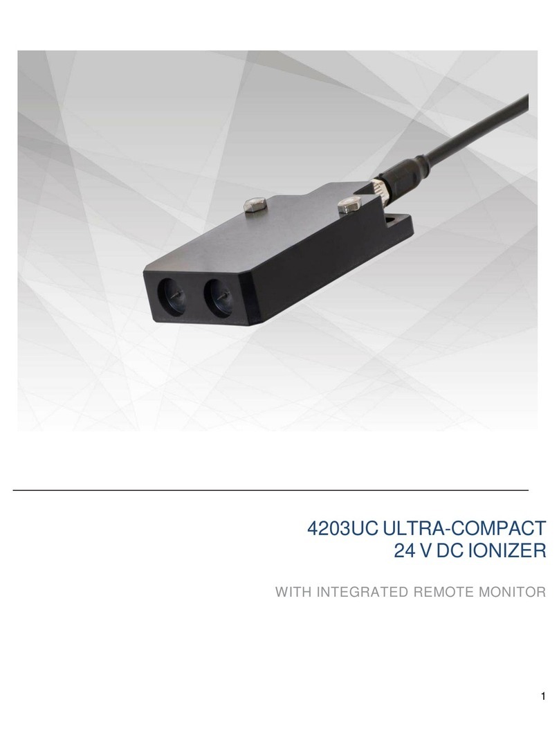
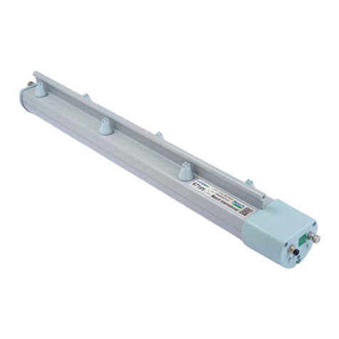
SMC Networks IZT40 Series User manual

1
Document No.IZ
※
-OMT0049 B
PRODUCT NAME
Ionizer
MODEL / Series
IZT40,41,42series

2
Contents
Safety Instructions ...................................................................................................................................................................... 3
1. How to Order..........................................................................................................................................................................11
1-1. System construction......................................................................................................................................................11
1-2. How to Order...................................................................................................................................................................14
1-2-1. Product number for single unit (to order separately).................................................................................................15
1-2-2. Made to Order...........................................................................................................................................................16
1-2-3. Accessories (ordered separately)..............................................................................................................................17
1-2-4. Sold separately .........................................................................................................................................................18
2. Procedures to Operation.......................................................................................................................................................20
2-1. Flow chart to operation..................................................................................................................................................20
2-2. Initial setting (Initial setting is not necessary for IZT40).............................................................................................20
3. Installation and wiring .........................................................................................................................................................21
3-1. Installation of Ionizer......................................................................................................................................................21
3-1-1. Precautions for Installation........................................................................................................................................21
3-1-2. Adjustment of Pressure (Flow adjustment)................................................................................................................21
3-1-3. Selection of piping port size ......................................................................................................................................21
3-1-4. Distance for installation.............................................................................................................................................22
3-1-5. Installation of bracket for bar.....................................................................................................................................22
3-1-6. Connecting the controller and high voltage power supply module ............................................................................23
3-1-7. Installing the controller and high voltage power supply module ................................................................................25
3-1-8. Routing of cables ......................................................................................................................................................30
3-2. Wiring..............................................................................................................................................................................33
3-2-1. Ground the ground terminal......................................................................................................................................33
3-2-2. Connection Circuit.....................................................................................................................................................33
3-2-3. Wiring of the AC adapter...........................................................................................................................................35
3-3. Timing chart....................................................................................................................................................................36
3-3-1. IZT40.........................................................................................................................................................................36
3-3-2. IZT41、IZT42.............................................................................................................................................................39
4. Function................................................................................................................................................................................43
4-1. Name of Parts .................................................................................................................................................................43
4-1-1. Controller ..................................................................................................................................................................43
4-1-2. High voltage power supply module ...........................................................................................................................45
4-2. Operation modes............................................................................................................................................................46
4-2-1. Operation modes of IZT40 and IZT41.......................................................................................................................46
4-2-2. Operation modes of IZT42 ........................................................................................................................................46
4-3. High voltage power supply module CH number setting .............................................................................................47
4-4. Controller setting............................................................................................................................................................48
4-4-1. Operation overview...................................................................................................................................................48
4-4-2. Channel selection mode............................................................................................................................................50
4-4-3. Frequency set mode .................................................................................................................................................51
4-4-4. Offset voltage adjustment mode................................................................................................................................52
4-4-5. Balance control selection mode ................................................................................................................................53
4-4-6. Maintenance detection level selection mode.............................................................................................................54
4-4-7. Key-lock setting mode...............................................................................................................................................55
4-4-8. Ion generation stop mode .........................................................................................................................................56
4-5. Alarm function................................................................................................................................................................57
4-5-1. Alarms for IZT40........................................................................................................................................................57
4-5-2. Alarms for IZT41 and IZT42 ......................................................................................................................................58
4-5-3. Details of the alarms .................................................................................................................................................59
5. Performance...........................................................................................................................................................................61
5-1. Installation distance and discharge time (discharge time of 1000V→100V).............................................................61
5-2. Potential amplitude ........................................................................................................................................................63
5-3. Static neutralization range.............................................................................................................................................64
5-4. Flow - Pressure characteristics ....................................................................................................................................67
6. Dimensions ............................................................................................................................................................................68
7. Specifications ........................................................................................................................................................................77
8. Troubleshooting.....................................................................................................................................................................78
9. Maintenance...........................................................................................................................................................................79
3
Safety Instructions
These safety instructions are intended to prevent hazardous situations and/or equipment damage.
These instructions indicate the level of potential hazard with the labels of “Caution,” “Warning” or “Danger.”
They are all important notes for safety and must be followed in addition to International Standards (ISO/IEC)*1) ,
and other safety regulations.
*1) ISO 4414: Pneumatic fluid power -- General rules relating to systems.
ISO 4413: Hydraulic fluid power -- General rules relating to systems.
IEC 60204-1: Safety of machinery -- Electrical equipment of machines .(Part 1: General requirements)
ISO 10218: Manipulating industrial robots -Safety.
etc.
Caution
Caution indicates a hazard with a low level of risk which, if not avoided, could result
in minor or moderate injury.
Warning
Warning indicates a hazard with a medium level of risk which, if not avoided, could
result in death or serious injury.
Danger
Danger indicates a hazard with a high level of risk which, if not avoided, will result
in death or serious injury.
Warning
1. The compatibility of the product is the responsibility of the person who designs the equipment or
decides its specifications.
Since the product specified here is used under various operating conditions, its compatibility with specific
equipment must be decided by the person who designs the equipment or decides its specifications based on
necessary analysis and test results.
The expected performance and safety assurance of the equipment will be the responsibility of the person who
has determined its compatibility with the product.
This person should also continuously review all specifications of the product referring to its latest catalog
information, with a view to giving due consideration to any possibility of equipment failure when configuring the
equipment.
2. Only personnel with appropriate training should operate machinery and equipment.
The product specified here may become unsafe if handled incorrectly.
The assembly, operation and maintenance of machines or equipment including our products must be
performed by an operator who is appropriately trained and experienced.
3. Do not service or attempt to remove product and machinery/equipment until safety is confirmed.
1.The inspection and maintenance of machinery/equipment should only be performed after measures to
prevent falling or runaway of the driven objects have been confirmed.
2.When the product is to be removed, confirm that the safety measures as mentioned above are implemented
and the power from any appropriate source is cut, and read and understand the specific product precautions
of all relevant products carefully.
3. Before machinery/equipment is restarted, take measures to prevent unexpected operation and malfunction.
4. Contact SMC beforehand and take special consideration of safety measures if the product is to
be used in any of the following conditions.
1. Conditions and environments outside of the given specifications, or use outdoors or in a place exposed to
direct sunlight.
2. Installation on equipment in conjunction with atomic energy, railways, air navigation, space, shipping,
vehicles, military, medical treatment, combustion and recreation, or equipment in contact with food and
beverages, emergency stop circuits, clutch and brake circuits in press applications, safety equipment or
other applications unsuitable for the standard specifications described in the product catalog.
3. An application which could have negative effects on people, property, or animals requiring special safety
analysis.
4.Use in an interlock circuit, which requires the provision of double interlock for possible failure by using a
mechanical protective function, and periodical checks to confirm proper operation.

4
Safety Instructions
Caution
1. The product is provided for use in manufacturing industries.
The product herein described is basically provided for peaceful use in manufacturing industries.
If considering using the product in other industries, consult SMC beforehand and exchange
specifications or a contract if necessary.
If anything is unclear, contact your nearest sales branch.
Limited warranty and Disclaimer/Compliance Requirements
The product used is subject to the following “Limited warranty and Disclaimer” and “Compliance Requirements”.
Read and accept them before using the product.
Limited warranty and Disclaimer
1.The warranty period of the product is 1 year in service or 1.5 years after the product is
delivered,whichever is first.2)
Also, the product may have specified durability, running distance or replacement parts. Please
consult your nearest sales branch.
2. For any failure or damage reported within the warranty period which is clearly our responsibility,
a replacement product or necessary parts will be provided.
This limited warranty applies only to our product independently, and not to any other damage
incurred due to the failure of the product.
3. Prior to using SMC products, please read and understand the warranty terms and disclaimers
noted in the specified catalog for the particular products.
2) Vacuum pads are excluded from this 1 year warranty.
A vacuum pad is a consumable part, so it is warranted for a year after it is delivered.
Also, even within the warranty period, the wear of a product due to the use of the vacuum
pad or failure due to the deterioration of rubber material are not covered by the limited
warranty.
Compliance Requirements
1. The use of SMC products with production equipment for the manufacture of weapons of mass
destruction(WMD) or any other weapon is strictly prohibited.
2. The exports of SMC products or technology from one country to another are governed by the
relevant security laws and regulation of the countries involved in the transaction. Prior to the
shipment of a SMC product to another country, assure that all local rules governing that export
are known and followed.
Caution
SMC products are not intended for use as instruments for legal metrology.
Measurement instruments that SMC manufactures or sells have not been qualified by type approval tests
relevant to the metrology (measurement) laws of each country.
Therefore, SMC products cannot be used for business or certification ordained by the metrology
(measurement) laws of each country.
The product is provided for use in manufacturing industries.
The product herein described is basically provided for peaceful use in manufacturing industries.
If considering using the product in other industries, consult SMC beforehand and exchange specifications or a
contract if necessary.
契約などを行ってください。
! Caution
SMC products are not intended for use as instruments for legal metrology.
Measurement instruments that SMC manufactures or sells have not been qualified by type approval tests
relevant to the metrology (measurement) laws of each country.
Therefore, SMC products cannot be used for business or certification ordained by the metrology
(measurement) laws of each country.

5
1) This product is intended for use in general factory automation equipment.
·If considering using the product for other applications (especially those indicated in (4) on page 3), please
consult SMC beforehand.
2) Use within the specified voltage and temperature range.
·Operation with a voltage other than that specified can cause malfunction, damage to the product, electric
shock or fire.
3) Use clean compressed air as fluid. (Air quality Class 2.6.3 specified in ISO 8573-1: 2012 is
recommended.)
·Never use flammable gas or an explosive gas as a fluid and never use this product in the presence of such
gases.
·This may lead to fire or explosion. Please contact SMC if using for fluids other than compressed air.
4) This product is not designed to be explosion proof.
·Never use in an atmosphere of potentially explosive dust, flammable gas or explosive gas. Fire or an
explosion can result.
1) Clean room specification is not available.
·When using in a clean room environment, confirm the required cleanliness before use.
·Fine particles are generated due to wear of emitters and motor sliding during operation.
1) Reserve an enough space for maintenance, piping and wiring.
·Please take into consideration that the one-touch fittings for supplying air, need enough space for the air
tubing to be easily attached/detached.
·To avoid unreasonable stress applied to the connector and one-touch fitting mounting parts, bending of the
cable or air tubing should be more than the minimum bending radius.
·If the cable is bent in an acute angle or load is applied to the cable repeatedly, it may cause malfunction, wire
damage or fire.
Minimum bending radius: Power supply cable: 40 mm
Separate cable (optional): 40mm
High voltage cable: 30mm
NOTE: This is an allowable bend radius at 20oC. Bend radius should be larger at lower than 20oC.
Regarding the minimum bending radius of the air tubing, refer to the operation manual or catalog
for tubing.
2) Wiring high voltage cable
·Use specified cable holder (IZT40-E1 or IZT40-E2) for installing high voltage cables.
·Follow the items below when installing high voltage cables. If items below are not followed, insulation
performance of high voltage cable decreases, causing the failure of ionizer, leading to electrical shock or fire.
a. Do not cut the cable.
b. Keep the minimum bend radius of the cable.
c. Do not tighten the cable too much by tying band. Do not deform the cable by placing object on the cable.
d. Avoid the factor of cable runaway such as cable duct.
e. Do not twist or damage to the cable. If the cable is damaged, it should be replaced.
3) Fix the high voltage cable connector using 2 screws included in accessory.
·Fix the connector using 2 cross recessed round head screws (M4 x10L) referring to Table 1. Reference of
tightening torque.
Warning
Caution
Warning
Mounting
Selection

6
4) Mount to the flat surface and do not apply impact load or excessive external force.
·Mounting on an uneven surface will apply excessive force to the housing and bracket, which may lead to
damage or failure.
·Do not drop or apply excessive shock. Otherwise, damage or an accident may occur.
5) Install the product so that the bar does not have an excessive deflection.
·For a bar length of 820mm or longer, support the bar at both ends and in the middle by using brackets
(IZS40-BM1 or IZT40-BM2). If the bar is held only at the both ends, self-weight of the bar causes deflection,
resulting in damage or deformation to the bar.
6) Avoid using in a place where noise (electromagnetic wave and surge) is generated.
·If the product is used in an environment where noise is generated, it may lead to malfunction or
deterioration or damage of the internal elements.
·When the presence of noise is suspected, take preventive measures against noise and avoid the crossing
wires such as power line and high voltage line.
7) Tighten the screws to the specified torque.
·If the screws are tightened in excess of the specified torque range, it may damage the mounting screws or
mounted areas.
·If the tightening torque is insufficient, the mounting screws and brackets may become loose.
8) Do not directly touch the emitters.
·Do not directly touch the emitter with your finger. If the needle sticks to your finger, or electrical shock makes
an instantaneous rapid body motion to escape from the shock, causing injury.
·If emitter or cartridge is damaged by tools, etc., it may interfere with the specified function and performance,
and may also cause operation failure and accident.
9) Do not affix any tape or labels to the controller, high voltage power supply module or bar.
·If the tape or label contains any conductive adhesive or reflective paint, a dielectric phenomenon may occur
due to ions arising from such substances, resulting in electrostatic charging or electric leakage, causing
malfunction, breakage, electric shock or fire.
Parts Product No. Connection Screw(Accessory) Tightening torque Note
Controller 2pcs. 0.25 to 0.35Nm
High voltage power
supply module
2pcs. 0.25 to 0.35Nm
Spacer for separate cable D-sub connector(plug) 2pcs.
0.40 to 0.60Nm
Intermediate bracket 2
IZT40-BM2
Bracket
(for angle adjustment)
M4x16L
2pcs.
0.47 to 0.49Nm
Intermediate bracket 1
IZT40-BM1
0.72 to 0.76Nm
Direct connection
Mounting angle adjustment
Cable holder
IZT40-E□
Location
M4x8L
(Recommended)
2pcs.
0.19 to 0.21Nm
Wiring high voltage cable
Install to DIN rail
Bar
(High voltage cable with connector)
IZTB4□-□□□□□-□-□
High voltage power
supply module
M4x10L
2pcs.
0.49 to 0.53Nm
Mounting of high voltage cable
High voltage power
supply module
Separate cable
IZT40-CF□
Separate connection
DIN rail mounting bracket
IZT40-B□
Controller
M4x6L
2pcs.
1.30 to 1.50Nm
DIN rail mounting bracket
1.30 to 1.50Nm
DIN rail
M4x6L
2pcs.
1.30 to 1.50Nm
M4x6L
IZT40-B2:4pcs.
IZT42-B3:8pcs.
Controller
IZTC40
IZTC41
High voltage power
supply module
M4x30L
2pcs.
0.22 to 0.24Nm
Table 1. Reference of tightening torque
End bracket
IZT40-BE□
Bar end bracket
M4x8L
2pcs.
0.51 to 0.55Nm
Installation of bracket for bar
M4x8L
2pcs.
0.72 to 0.76Nm
The emitter carries high voltage. If foreign matter is
inserted or human body touches the emitter,
electrical shock or instantaneous reaction of body to
escape from the shock, causing injury.
High voltage caution

7
10) Be sure to remove power supply and air supply to the controller, high voltage power supply module
and bar before starting the product installation.
·If installation or adjustment is performed being supplied with power or air, electric shock, failure or injury can
result.
11) High voltage power supply module uses a fan. 20mm or
more space from the exhaust port is necessary for
ventilation.
·Or install the product in a ventilated location so peripheral
device are not affected.
12) Do not damage the cable or apply a heavy object or pinch
the cable. Avoid repeatedly bending or stretching the
cable.
·It may cause an electric shock, fire, or breaking of wire.
13) Do not carry this product by holding its cables.
·It may cause an injury or damage to the product.
1) When IZT4□series is installed, keep space below from structures or components.
·If there are electrically conductive objects such as walls or structures close to the bar, generated ions may
not reach the target object effectively or product failure or electric shock can result due to dielectric or
short-circuit.
2) After installation, verify the performance of this product.
·The performance of the product varies depending on the surrounding installation and operating conditions.
After installation, verify the performance of this product.
3) When installing Ionizers which operate in DC mode (one polarity, positive or negative) with IZT41 or
IZT42 close together, they should be positioned at least two meters away from each other.
·When IZT41 or IZT42 which operates in AC close to
the Ionizer which operates in DC mode, separate
them by at least two meters. The offset voltage
(ion balance) may not be adjusted by the built-in
sensor due to the ions discharged from the Ionizer
which operates in DC mode.
4) Use specified end bracket.
Caution
Unit :mm
18.1
72.1
18.1
50.5
50.5
IZT40/41 IZT42
Exhaust port
Controller
High voltage
power supply
module
2m or more
DC mode
AC mode
In case of IZTB40
Bracket at the end of the bar
Fitting

8
1) Before wiring, ensure that the power supply capacity meets the specification and that the voltage is
within the specification. Product damage or malfunction can result.
2) To maintain product performance, the power supply should be UL Class 2 certified by National Electric
Code (NEC) or evaluated as a limited power source according to UL60950.
3) To maintain the product performance, ground the product with an earth ground cable with a resistance
of 100 Ω or less. If the product is not grounded, it is not possible to secure the performance and may
lead to product failure or malfunction.
4) Wiring (including insertion and removal of the power supply connector) should never be carried out
with the power supply ON. Otherwise, an electrical shock or accident may occur.
5) Use specified cable for connecting the ionizer controller, high voltage power supply module and bar.
Do not disassemble or retrofit them. Disassembling or modifying the product may cause product,
electric shock or fire. The product will not be guaranteed if it is disassembled and/or modified.
6) Ensure the safety of wiring and surrounding conditions before supplying power.
7) Do not connect or disconnect the connectors (including power source) while the power is supplied.
Failure to follow this procedure may cause product malfunction.
8) If the power and high voltage cables are routed together, the product may malfunction due to noise.
Route the Ionizer wires separately.
9) Confirm that the wiring is correct before operation. Incorrect wiring will lead to product damage or
malfunction.
10) Flush the piping before connecting. Before piping this product, exercise caution to prevent particles,
water drops, or oil contents from entering the piping.
1) Operate the product in the specified fluid temperature range and ambient temperature range.
·Operating fluid temp. and ambient temp. range: Controller 0 to 40oC, high voltage power supply module 0 to
40oC, bar 0 to 50oC,AC adapter 0 to 40oC.
·Do not use the product in locations where the temperature may change suddenly even if the ambient
temperature range is within the specified limits, resulting in condensation.
2) Do not use this product in an enclosed space.
·This product utilizes the corona discharge phenomenon. Do not use the product in an enclosed space as
ozone and nitrogen oxides exist, even though in marginal quantities.
3) Environments to avoid
·Never use or store under the following conditions. These may cause an electric shock, fire, etc.
a. Use in the environment which ambient temperature is out of the product specification.
b. Use in the environment which ambient humidity is out of the product specification.
c. Environment where abrupt temperature changes may cause condensation.
d. Environment where corrosive gas, flammable gas or other volatile flammable substances are stored.
e. Environment where the product may be exposed to conductive powder such as iron powder or dust, oil
mist, salt, organic solvent, machining chips, particles or cutting oil (including water and any liquids), etc.
f. Paths of direct air flow, such as air conditioners.
g. Enclosed or poorly ventilated environment
h. Locations which are exposed to direct sunlight or heat radiation.
i. Areas where strong electromagnetic noise is generated, such as strong electrical and magnetic fields or
supply voltage spikes.
j. Environment where static electricity is generated to the product.
k. Locations where strong high frequency is generated.
l. Locations which are subject to potential lightning strikes.
m. In an area where the product may receive direct impact or vibration.
n. Areas where the product may be subjected to forces or weight that could cause physical deformation.
Warning
Operating / Storage Environment
Warning
Wiring and Piping
Wiring and Piping

9
4) Do not use air containing mist and/or dust.
·Air containing mist and/or dust may cause performance deterioration, and reduce the maintenance cycle.
·Install a dryer (IDF series), air filter (AF/AFF series), and/or mist separator (AFM/AM series) to obtain clean
compressed air (air quality of Class 2.4.3, 2.5.3, 2.6.3 or higher according to ISO 8573-1: 2010 (JIS
B8392-1:2012) is recommended for operation.
5) Controller, high voltage power supply module, bar and AC adapter are not resistant to lightening
surge.
1) Perform maintenance regularly and clean the emitters.
·Check regularly that the product is not operating with
undetected failures.
·The maintenance must be carried out by an operator
who has sufficient knowledge and experience.
·If the product is used for an extended period with dust
present on the emitters, the product performance will be
reduced.
·Maintenance detection function is installed to
IZT41 and IZT42. When the emitter contamination is
detected, clean the emitter.
·In cases where the maintenance detection function is not used on the IZS41 or IZS42 or IZT40 is used,
perform neutralizing performance test and set maintenance cycle for periodic cleaning.
·Emitter contamination level is different depending on the installation environment and supply pressure.
Refer to section "9. Maintenance" for details.
·If the performance is not recovered after cleaning, it is possible that emitters are worn. Replace the emitter
cartridge.
2) Be sure to remove power supply and air supply to the controller, high voltage power supply module
and bar before cleaning the emitter or replacing the emitter cartridge.
·Never touch the emitter with the power supplied to the controller, high voltage power supply module or bar.
Electric shock may cause injury.
·If the emitter cartridge is removed while air is supplied, the emitter cartridge jumps out by compressed air.
Replace the emitter cartridge after discharging the supply air.
·If emitter cartridges are not securely mounted to the bar, they may eject or release when air is supplied to the
product.
·Securely mount or remove the emitter cartridges referencing the instructions shown below.
·Securely mount or remove the emitter cartridges with hands and do not use tools.
(Tightening torque: 0.2 to 0.3 Nm)
3) Do not disassemble or modify the product.
·Disassembling or modifying the product may cause product, electric shock or fire. The product will not be
guaranteed if it is disassembled and/or modified.
4) Do not operate the product with wet hands.
·Never operate the product with wet hands. It may cause electric shock or other accidents.
Warning
Maintenance / Check
(1)Rotate the cartridge
90 degrees in the
counter-clockwise
direction.
(2) Pull to remove.
(1) Insert the cartridge into the bar
so that the longer side
of the cartridge is
mounted at a right
angle to the bar.
(2) Rotate the emitter cartridge for
90 degrees in the clockwise
direction, and match the markings
on the bar and on the
cartridge to fix.
Removal of the emitter
cartridge
Mounting of the emitter
cartridge
・This product contains a high voltage
generation circuit. When performing
maintenance inspection, be sure to
confirm that the power supply to the
ionizer is turned off.
・Never disassemble or modify the product,
as this can cause loss of product
functionality, and there is also a risk of
electric shock and earth leakage.
High voltage caution

10
1) Do not apply excessive external force or shock (100m/s2 or more) to the product
·Even if the there are no problems with the appearance of the controller, high voltage power supply module or
bar, the damage of the internal components may cause malfunction.
2) When the bar length exceeds 820mm, hold the both ends and the middle of the bar so that moment
load is not applied.
·Handling the product by holding either end of the bar may cause deformation or damage to the product.
3) Power cable must be connected and disconnected by hand.
·Open and close too much may damage the drain cock.
·Hold the connector by hand and straightly pull it out.
·If the connector has lock mechanism, release the lock and then pull out the connector.
4) If smoking, fire or smell occurs in the product, immediately shut off the power supply.
5) Do not touch the Apart of the high voltage connector by hand. Be careful so that moisture or foreign
matter does not adhere to the connector.
·Do not touch theA part of the high voltage connector by hand while handling.
·Keep the high voltage connector free from contamination. Adhesion of oil or foreign matter on the A part
may cause high voltage electric leakage.
·If moisture, oil, or foreign matter adheres to theA part, clean it with ethanol.
Caution
Handling
High voltage connector
(Back)
A
A

11
1. How to Order
1-1. System construction
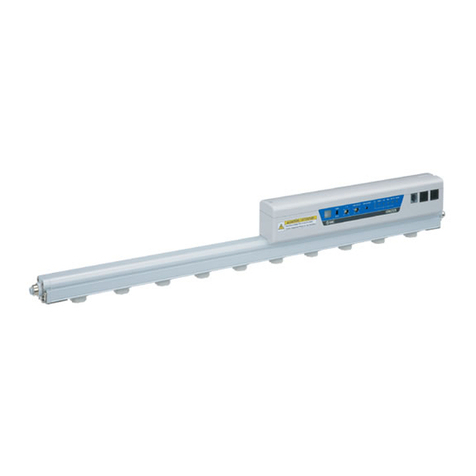
·IZT4□series consists of the bar (ion generator), high voltage power supply module, and controller. It is
necessary to combine each equipment.
·Refer to IZT4□Table of combination below for combining equipment. Combinations other than those in the
Table are not possible.
·The controller and high voltage power supply module can be directly connected or installed separately .
·When multiple products are installed, up to 4 high voltage power supply modules can be connected to one
controller. Please refer to ①and ②below for the type of high voltage power supply module depending on
the controller.
①For IZTC40 (controller), only IZTP40 is applicable.
②For IZTC41 (controller), IZTP41 and IZTP42 are applicable.
Controller (IZTC40, IZTC41)
High voltage power supply module (IZTP40, IZTP41, IZTP42)
Bar (ion generating part) (IZTB40、IZTB42)
IZTC40-□
(Controller for IZT40)
IZTC41-□□
(Controller for IZT41/IZT42)
IZTP40
(High voltage power supply module
for IZT40)
IZTP41
(High voltage power supply module
for IZT41)
IZTP42
(High voltage power supply module
for IZT42)
IZTB40‐□□□□□-□-□
(Bar for IZT40/IZT41)
IZTB42‐□□□□□-□-□
(Bar for IZT42)
Table2. IZT4□Table of combination (Representative model that can be connected)
Series Controller
High voltage power
supply module
Bar
IZT40 IZTC40 IZTP40
IZT41 IZTP41
IZT42 IZTP42 IZTB42
IZTC41
IZTB40

12
Direct connection
Example of connecting IZTC40,
IZTP40 and IZTB40 (IZT40)
Example of connecting IZTC41,
IZTP42 and IZTB42 (IZT42)
Example of connecting IZTC40, IZTP40
and IZTB40 (4pcs.)
Example of connecting IZTC41, IZTP41
and IZTB40 (4pcs.)
Example of connecting IZTC41, IZTP42 and IZTB42 (4pcs.)
Example of connecting IZTC41,
IZTP41 and

13
Separate connection
Example of connecting IZTC40, IZTP40 and IZTB40 (4pcs.)
Example of connecting IZTC40,
IZTP40 and IZTB40 (IZT40)
Example of connecting IZTC41, IZTP41 and IZTB40 (4pcs.)
Example of connecting IZTC41, IZTP42 and IZTB42 (4pcs.)
Example of connecting IZTC41,
IZTP42 and IZTB42 (IZT42)
Example of connecting IZTC41,
IZTP41 andIZTB40 (IZT41)

14
1-2. How to Order
·The product number consists of the controller, high voltage power supply module and bar (1 of each).
·When multiple high voltage power supply modules and bars are added to one controller, choose the
equipment according to the product number for a single unit.
Bar + High voltage power supply module + Controller
40 34 D 1 6H R 3 F U
42 34 D 1 6H R 3 F U
IZT
-
-
-
|
|
|
|
|
|
|
|
IZT
-
-
-
|
|
(2)
(3)
(4)
(5)
(6)
(7)
(8)
(9)
(10)
(11)
(12)
(1)
Symbol
40
Model
Standard type
(1) Model
(2) Model
Symbol
41
42
Model
AC type
Dual AC type
640
112
130
160
190
232
1900
2320
2500
(3) Bar length
Bar length (mm)
820
1120
1300
1600
250
Bar length (mm)
160
220
340
400
460
580
Symbol
16
22
34
40
46
58
64
Symbol
82
※Refer to the bore size in the table below for selection of
One-touch fittings.
5L
7L
9L
BL
Inch size
ø3/16" straight
ø1/4" straight
ø5/16" straight
ø3/8" straight
ø3/16" elbow
ø1/4" elbow
ø5/16" elbow
ø3/8" elbow
Symbol
5H
7H
9H
BH
AL
Metric size
ø4 straight
ø6 straight
ø8 straight
ø10 straight
ø4 elbow
ø6 elbow
ø8 elbow
ø10 elbow
8H
AH
4L
6L
8L
(6) One-touch Fitting
Symbol
4H
6H
P
PNP
※None of the Input/Output functions can be used when the
AC adapter is being used.
(8) Input/ Output Speicifications
Symbol
Input/ Output
Nil
NPN
Symbol
D
V
E
S
Type
Material
High speed static
neutralization cartridge
Energy saving high-
efficiency cartridge
Tungsten
Silicon
Tungsten
Silicon
L
Energy saving static
neutralization cartridge
Tungsten
M
Silicon
(4) Emitter Cartridge Type/ Materials
3
3
5
5
※To use AC adapter, specify "N", and select AC adapter with
the option number.
10
10
15
15
[N]
None
(9) Power Supply Cable Length
Symbol
Length (m)
2
3
No of bracket
End bracket
2,440 to 2,500
1,660 to 2,380
820 to 1,600
160 to 760
Intermediate bracket
Bar length mm
2
None
1
(10) Bracket for bar
※Number of intermediate bracket depends on the bar length.
(See table below)
Symbol
Nil
B
F
Type
Without Bracket
With bracket 1
With bracket 2
R
Plug location
Without plug
High voltage cable side
The opposite side of the high voltage cable
(7) Plug Location
Symbol
Nil
Q
Included
None
Included
U
W
Y
For controller
None
Included
Included
None
(11) DIN rail bracket for controller, high voltage power
supplymodule
Symbol
Nil
For high voltage power supply module
None
(12) Made to Order
4H/ 4L 160 to 220 160 to 460 4H / 4L 160 to 460 160 to 820 4H/ 4L 160 to 1600 160 to 2500
6H/ 6L 160 to 580 160 to 1120 6H/ 6L 160 to 1120 160 to 2320 6H/ 6L 160 to 2500 160 to 2500
8H/ 8L 160 to 820 160 to 1900 8H/ 8L 160 to 1900 160 to 2500 8H/ 8L 160 to 2500 160 to 2500
AH / AL 160 to 1600 160 to 2500 AH / AL 160 to 2500 160 to 2500 AH / AL 160 to 2500 160 to 2500
5H/ 5L 160 to 400 160 to 640 5H / 5L 160 to 640 160 to 1300 5H/ 5L 160 to 2500 160 to 2500
7H/ 7L 160 to 640 160 to 1300 7H/ 7L 160 to 1300 160 to 2500 7H/ 7L 160 to 2500 160 to 2500
9H/ 9L 160 to 820 160 to 1900 9H/ 9L 160 to 1900 160 to 2500 9H/ 9L 160 to 2500 160 to 2500
BH / BL 160 to 1600 160 to 2500 BH/ BL 160 to 2500 160 to 2500 BH / BL 160 to 2500 160 to 2500
Bar length (mm)
Single end
piping
Double ends
piping
Single end
piping
Double ends
piping
Single end
piping
Double ends
piping
One-touch
fitting
symbol
Bar length (mm)
One-touch
fitting
symbol
Bar length (mm)
One-touch
fitting
symbol
Recommended piping bore size
High speed static neutralization
cartridge
Energysaving static neutralization
cartridge
Energysaving high-efficiency
cartridge
(5) High voltage cable length
1
Symbol
1
2
3
High voltage cable length (m)
1
2
3
Number of High Voltage Cable Holder
※Number of included cable holder is different depending on
the high voltage cable length (Table below).
IZT41
IZT42
Straight
Symbol
IZT40
Elbow
Straight
Elbow
Straight
Elbow
1
2
3
1
2
3
1
1
2
4
6
2
2
2
1
1
2
3
1
1

15
1-2-1. Product number for single unit (to order separately)
Table for combination
Bar
42
IZTP
●Model
42
Model
Standard type
AC type
Dual AC type
Symbol
40
41
40 3
41 3
|
|
IZTC
-
IZTC
-
●Power supply cable length
※To use AC adapter, specify"N", and
select AC adapter with the option number.
Symbol
15
[N]
15
None
Length (m)
Symbol
3
5
10
Length (m)
3
5
10
40
41
AC,
Dual AC type
Standard type
Model
Controller type ●
Symbol
Symbol
Nil
P
Input / output specifications ●
Input/ Output
NPN
PNP
High voltage power supply module
Controller
41
IZT40
●
●
●
Bar / IZTB
High voltage power supply module / IZTP
Controller / IZTC
40
42
40
41
42
40
●
IZT42
●
●
●
IZT41
●
●
40 16 D 1 6H R F
IZTB
-
-
-
(1)
(2)
(3)
(4)
(5)
(6)
(7)
(8)
(1) Model
Symbol
Model
40
Standard, AC type
42
Dual AC type
58
580
232
2320
64
640
250
2500
40
400
160
1600
46
460
190
1900
22
220
112
1120
34
340
130
1300
(2) Bar length
Symbol
Bar length (mm)
Symbol
Bar length (mm)
16
160
82
820
V
Energy saving high-
efficiency cartridge
Tungsten
S
Silicon
(3) Emitter Cartridge Type/ Materials
Symbol
Type
Material
D
High speed static
neutralization cartridge
Tungsten
E
Silicon
L
Energy saving static
neutralization cartridge
Tungsten
M
Silicon
BL
ø3/8" elbow
※Refer to the bore size in the table below for selection of
One-touch fittings.
5L
ø3/16" elbow
7L
ø1/4" elbow
9L
ø5/16" elbow
7H
ø1/4" straight
9H
ø5/16" straight
BH
ø3/8" straight
AL
ø10 elbow
Symbol
Inch size
5H
ø3/16" straight
4L
ø4 elbow
6L
ø6 elbow
8L
ø8 elbow
6H
ø6 straight
8H
ø8 straight
AH
ø10 straight
(5) One-touch Fitting
Symbol
Metric size
4H
ø4 straight
Nil
Without plug
Q
High voltage cable side
R
The opposite side of the high voltage cable
(6) Plug location
Symbol
Plug location
160 to 760
2
None
820 to 1,600
1
1,660 to 2,380
2
2,440 to 2,500
3
F
With bracket 2
※Number of intermediate bracket depends on the bar length.
(See table below)
No of bracket
Bar length mm
End bracket
Intermediate bracket
(7) Bracket for bar
Symbol
Type
Nil
without Bracket
B
With bracket 1
(8) Made to Order
4H/ 4L 160 to 220 160 to 460 4H/ 4L 160 to 460 160 to 820 4H/ 4L 160 to 1600 160 to 2500
6H/ 6L 160 to 580 160 to 1120 6H / 6L 160 to 1120 160 to 2320 6H / 6L 160 to 2500 160 to 2500
8H/ 8L 160 to 820 160 to 1900 8H / 8L 160 to 1900 160 to 2500 8H / 8L 160 to 2500 160 to 2500
AH / AL 160 to 1600 160 to 2500 AH / AL 160 to 2500 160 to 2500 AH / AL 160 to 2500 160 to 2500
5H/ 5L 160 to 400 160 to 640 5H/ 5L 160 to 640 160 to 1300 5H/ 5L 160 to 2500 160 to 2500
7H/ 7L 160 to 640 160 to 1300 7H / 7L 160 to 1300 160 to 2500 7H / 7L 160 to 2500 160 to 2500
9H/ 9L 160 to 820 160 to 1900 9H / 9L 160 to 1900 160 to 2500 9H / 9L 160 to 2500 160 to 2500
BH / BL 160 to 1600 160 to 2500 BH/ BL 160 to 2500 160 to 2500 BH / BL 160 to 2500 160 to 2500
Bar length (mm)
Bar length (mm)
Bar length (mm)
Recommended piping bore size
One-touch
fitting
symbol
Single end
piping
Double ends
piping
One-touch
fitting
symbol
Single end
piping
Double ends
piping
One-touch
fitting
symbol
Single end
piping
Double ends
piping
High speed static neutralization
cartridge
Energy saving static neutralization
cartridge
Energy saving high-efficiency
cartridge
2
3
3
1
3
1
6
2
2
2
1
2
1
4
2
Straight
Elbow
Straight
Elbow
1
1
1
1
1
2
3
3
※Number of included cable holder is different depending on
the high voltage cable length (Table below).
Number of High Voltage Cable Holder
Symbol
IZT40
IZT41
IZT42
Straight
Elbow
Symbol
High voltage cable length (m)
1
1
2
2
(4) High voltage cable length

16
40 52 D 1 6H R F X10
42 52 D 1 6H R F X10
40 52 D 1 6H R F X10
IZT
-
-
-
IZT
-
-
-
IZTB
-
-
-
41
Model ●
40
42
※Only bar is
ordered, 41 cannot
be selected.
※
Standard product number
●Bar length
208
2080
214
2140
220
2200
Symbol
Bar length (mm)
196
1960
202
2020
154
1540
1660
172
1720
1240
136
1360
1420
148
1480
1780
1840
226
2260
238
2380
244
2440
940
1000
1060
1180
166
184
178
118
Bar length (mm)
Symbol
142
280
520
700
760
880
Bar length (mm)
124
76
88
94
100
106
Symbol
28
52
70
40 34 D 1 6H R F X14
42 34 D 1 6H R F X14
40 34 D 1 6H R F X14
IZT
-
-
-
IZT
-
-
-
IZTB
-
-
-
41
Model ●
40
42
※Only bar is
ordered, 41 cannot
be selected.
※
Standard product number
16 22 34 40 46 58 64 82 112 130 160 190 232 250
160 220 340 400 460 580 640 820 1120 1300 1600 1900 2320 2500
Standard
Non-standard
●Bar length
Symbol
Length (mm)
The bar of non-standard length is available. Refer to the how to order above.
1-2-2. Made to Order
Bar + High voltage power supply module + Controller
Bar
Bar + High voltage power supply module + Controller
Bar
Symbol
Manufacturable bar length (Symbol) :10+6×n (n is an integer from 1 to 39)
(Use standard product when n is 1, 2, 4, 5, 6, 8, 9, 12, 17, 20, 25, 30, 37)
Non-standard bar length
Description
Specifications
-X10
-X14
With emitter cartridge drop prevention cover
An optional drop prevention cover is mounted to the ionizer as default.
Description
Specifications
Symbol

17
1-2-3.Accessories (ordered separately)
Emitter Cartridge (Common for IZT40,IZT41,IZT42)
Power supply cable (Common for IZT40, IZT41, IZT42)
Bracket for bar (Common for IZT40, IZT41, IZT42)
Cartridge color
White
Gray
Emitter material
Tungsten
Silicon
IZT40 -3
CP
Length (m)
3
5
10
15
Symbol
3
5
10
15
●Power supplycable length
IZT40-BE1
End Bracket 1
IZT40-BE2
End Bracket 2
IZT40-BM1
Intermediate bracket 1
IZT40-BM2
Intermediate Bracket 2
IZT40 -B
E1
E2
M1
M2
End bracket 2
Intermediate bracket 1
Intermediate bracket 2
Symbol
E1
End bracket 1
Type
●Bracket for bar
○: Possible to combine × : Not possible to combine
Table3. Bracket combination
End bracket 1
End bracket 2
Intermediate bracket 1
Intermediate bracket 2
○(angle adjustment +/-90o)
×
×
○(angle adjustment +/-15o)
※Select bracket referring to the combination in the table below.
Table4. No of bracket
※The following table lists the number of bracket required for
intermediate support based on the bar length.
Bar length mm
160 to 760
820 to 1,600
1,660 to 2,380
2,440 to 2,500
2 end brackets are necessary regardless of the bar length.
End bracket
Intermediate bracket
2
3
2
1
None
IZT40 -N D
●Emitter Cartridge Type/ Materials
Energy saving static
neutralization cartridge
Symbol
D
E
Tungsten
Material
Silicon
Type
High speed static
neutralization cartridge
L
M
Tungsten
Silicon
IZS40 -N V
●Emitter Cartridge Type/ Materials
Energy saving high-
efficiency cartridge
Type
Symbol
Material
V
Tungsten
S
Silicon

18
DIN rail mounting bracket for controller and high voltage power supply module
(Common for IZT40, IZT41, IZT42)
High voltage cable holder (Common for IZT40, IZT41, IZT42)
1-2-4. Sold separately
AC adapter (Common for IZT40, IZT41, IZT42)
IZT40 -E 1
●High voltage cable holder
2
Elbow
Symbol
1
Type
Straight
IZT40 -1
CG
Type
Symbol
●AC adapter
1
2
with AC cord
without AC cord
IZT40-E1
High voltage cable holder (straight)
IZT40-E2
High voltage cable holder (elbow)
AC adapter
AC cord
IZT40-B1
Controller DIN rail
bracket
IZT40-B2
High voltage power supply module
DIN rail mounting bracket
for IZTP40/IZTP41
IZT40-B3
High voltage power supply module
DIN rail mounting bracket
for IZTP42
IZT40 -B 1
●DIN rail mounting bracket
2
3
High voltage power supply module for IZT40/IZT41
High voltage power supply module for IZT42
Symbol
1
For controller
Type

19
Drop prevention cover (Common for IZT40, IZT41,IZT42)
Separate cable (Common for IZT40, IZT41, IZT42)
Emitter cleaning kit (Common for IZT40, IZT41, IZT42)
IZT40 -1
CF
2
3
3
●Separate cable length
Length (m)
1
2
Symbol
1
IZS30 -
M2
IZS30 -
A0201
IZS30 -
A0202
(Provided together with 1 felt pad
grindstone, 1 rubber grindstone,
and 2 replacement felt pads)
(Provided together with
10 replacement felt pads)
(Provided together with 1
replacement rubber grindstone)
IZS40 -E 2
●No. of emitter cartridge to be fixed
For 2pcs.
Type
For 3pcs.
For 4pcs.
For 5pcs.
4
5
Symbol
2
3
Image of the cover mounted
to the unit
IZS40-E5
Drop prevention cover 5pcs.
IZS40-E2 IZS40-E3 IZS40-E4 IZS40-E5 IZS40-E3 IZS40-E4 IZS40-E5 IZS40-E3 IZS40-E4 IZS40-E5
16 1
-- - 28 - 1 - 154 - - 5
22 - 1 - - 52 1 - 1 166 1 1 4
34 - - - 1 70 2 - 1 172 1 - 5
40 - 2 - - 76 1 1 1 178 - 1 5
46 - 1 1 - 88 - 1 2 184 - - 6
58 - - 1 1 94 - - 3 196 1 1 5
64 - - - 2 100 2 - 2 202 1 - 6
82 - 1 - 2 106 1 1 2 208 - 1 6
112 - 1 - 3 118 - 1 3 214 - - 7
130 - 2 - 3 124 - - 4 220 2 - 6
160 - 2 - 4 136 1 1 3 226 1 1 6
190 - 2 - 5 142 1 - 4 238 - 1 7
232 - 1 - 7 148 - 1 4 244 - - 8
250 - 2 - 7
No. of drop prevention cover needed
Symbol
for bar
length
No. of drop prevention cover needed
Symbol
for bar
length
Symbol
for bar
length
Table5. Standard bar length
Table6. Non-standard bar length

20
Start
Installationofionizerbody
Wiringof ionizer
Airpurge
Piping of ionizer
Pressuresetting
Initialsetting
Adjustmentofoffsetvoltage
(ionbalance)
Completed
Highvoltage powersupply
moduleCHnumbersetting
Yes
No.
PowersupplyisON
Frequencysetting
2. Procedures to Operation
2-1. Flow chart to operation
2-2. Initial setting (Initial setting is not necessary for IZT40)
·This product has a function which constantly monitors the emitter contamination. When emitter
contamination is detected, it is indicated by a signal output and LED. Initial setting is necessary for
maintenance detection.
·In the default setting "no" is displayed for the frequency display.
·The Initial setting is started by pressing the S button for 3 seconds or longer while "no" is displayed. To
revert to the default setting press the reset button during use.
·Connect and install the ionizer bar to be used before setting.
·When multiple bars are connected, assign the channel for which initial setting is necessary.
Refer to 4-4-2. Channel selection mode for channel setting.
·Do not disconnect the power supply during setting. (Initial setting is completed within 60 seconds.)
[Initial setting is necessary in following cases]
①When "no" is displayed in the frequency display.
②Bar is replaced.
③Installation environment is changed.
※For ②③, perform initial setting after pressing the reset button
and make sure that "no" is displayed in the frequency display.
It is recommended to start the initial setting for ③after replacing
the emitter cartridge. If initial setting is performed while the emitter
cartridge is not clean or is worn out, maintenance detection may not
work properly.
Refer to 3-1. Installation of Ionizer for details.
Refer to 3-2.Wiring.
Refer to 3-1. Installation of Ionizer for details.
Caution: Do not adjust the flow using the restrictor.
Refer to 3-1-2. Adjustment of Pressure (Flow adjustment).
Refer to 4-3. High voltage power supply module CH number setting.
Refer to 4-4-3. Frequency set mode.
Refer to 4-4-4. Adjustment mode of Offset Voltage
Refer to 2-2.Initial setting.( Initial setting is not necessary for IZT40)
Controller
(IZTC41)
Frequency
display
This manual suits for next models
2
Table of contents
Other SMC Networks Air Ionizer manuals

SMC Networks
SMC Networks IZS31 Series User manual

SMC Networks
SMC Networks IZS42 User manual

SMC Networks
SMC Networks IZT41 Series User manual

SMC Networks
SMC Networks IZG10 User manual

SMC Networks
SMC Networks IZN10E Series Instruction manual

SMC Networks
SMC Networks IZT43-L Series User manual

SMC Networks
SMC Networks IZS40-2020-08B-X10 User manual

SMC Networks
SMC Networks IZT43 Series User manual

SMC Networks
SMC Networks IZG10 User manual

SMC Networks
SMC Networks IZG10 User manual