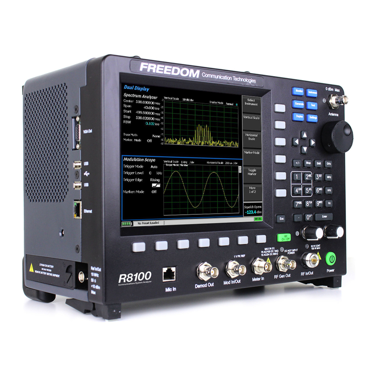
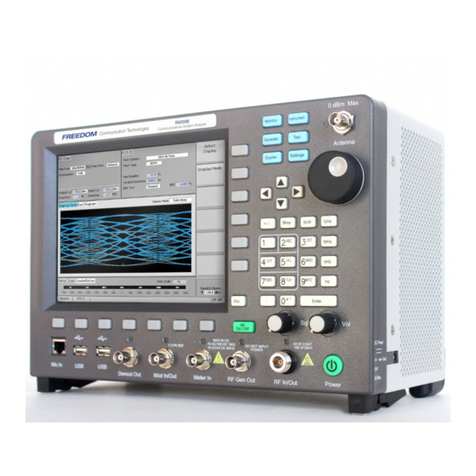
Freedom R8100 SERIES User manual

R8100 SERIES
COMMUNICATIONS SYSTEM ANALYZER
OPERATOR’S MANUAL
Documentation for firmware version 2.0.0.0
Freedom Communication Technologies
2002 Synergy Blvd. Suite 200
Kilgore Texas 75662 USA
Tel/Fax: +1-844-903-7333
Freedom Communication Technologies 2015
All Rights Reserved
FCT-1365
Printed in U.S.A

2
Table of Contents
Topic Page
LIMITED WARRANTY.............................................................................................................................................11
SOFTWARE LICENSE AGREEMENT.................................................................................................................12
1PRE-OPERATION OVERVIEW...............................................................................................................13
1.1 SCOPE OF MANUAL.....................................................................................................................13
1.2 SAFETY SUMMARY .......................................................................................................................13
1.2.1 Analyzer Grounding...................................................................................... 13
1.2.2Unit is Live When Plugged In ....................................................................... 13
1.2.3 Keep Away From Live Circuits ..................................................................... 13
1.2.4 Explosive Atmosphere.................................................................................. 13
1.3 WARNINGS AND CAUTIONS ...................................................................................................14
1.3.1 Analyzer Operating Voltage .......................................................................... 14
1.3.2 DC Power Source ......................................................................................... 14
1.3.3 Maximum Meter In Voltages......................................................................... 14
1.3.4 Replacement Fuses........................................................................................ 15
1.3.5 Other Cautions ............................................................................................. 15
1.3.6 User Maintenance of exterior surfaces........................................................... 15
1.4 SERVICE ............................................................................................................................................16
1.5 REPLACEMENT PARTS ORDERS ............................................................................................16
1.6 INSTALLATION..............................................................................................................................16
1.6.1 Packing ......................................................................................................... 16
1.6.2 Initial Set-up.................................................................................................. 16
1.6.3 Warm-up....................................................................................................... 16
1.7 Description..........................................................................................................................................16
1.8 Technical Specifications ....................................................................................................................20
1.9 Operator Interface and Controls......................................................................................................21
1.9.1 Front Panel Control Keys ............................................................................. 22
1.9.2 Front Panel Control Knobs........................................................................... 25
1.9.3 Front Panel Display and Indicators ............................................................... 26
2OPERATION..................................................................................................................................................30
2.1 Overview..............................................................................................................................................30

3
2.1.1 Basic navigation and operator control ........................................................... 30
2.1.2 Hot keys for fast navigation in Monitor, Audio, Display and Meter zones..... 33
2.2 Operating Instructions.......................................................................................................................34
2.2.1 RF Zone / Monitor Mode ............................................................................ 34
2.2.2 RF Zone / Generate Mode ........................................................................... 39
2.2.3 RF Zone / Duplex Mode.............................................................................. 41
2.2.4 Display Zone ................................................................................................ 60
2.2.5 Meter Zone................................................................................................... 73
2.2.6 Instrument Menu .......................................................................................... 81
2.2.7 Test Menu..................................................................................................... 92
2.2.8 Settings Menu ............................................................................................. 211
2.2.9 Screen Capture............................................................................................ 225
3REMOTE OPERATION........................................................................................................................... 226
3.1 BIOS Power-loss Setup .................................................................................................................. 226
3.2 DHCP Server Setup ........................................................................................................................ 227
3.3 Network Port Setup ........................................................................................................................ 228
3.4 Computer Setup............................................................................................................................... 229
3.4.1 Setup........................................................................................................... 229
3.4.2 Control ....................................................................................................... 230
3.5 Disable Remote Access .................................................................................................................. 230
3.6 Verification / Troubleshooting Information .............................................................................. 230
4TEST APPLICATIONS.............................................................................................................................. 232
4.1 FM Transmitter Testing ................................................................................................................. 232
4.1.1 Basic FM Transmitter Testing –initial setup ............................................... 232
4.1.2 Transmit Power, Frequency, and Frequency Deviation Measurements........ 233
4.1.3 Modulation Measurements .......................................................................... 233
4.1.4 Off-The-Air Measurements......................................................................... 234
4.2 FM Receiver Testing....................................................................................................................... 234
4.2.1 Basic FM Receiver Testing –initial setup .................................................... 234
4.2.2 Receiver Distortion Measurement ............................................................... 235
4.2.3 SINAD Measurement ................................................................................. 236
4.2.4 Modulation Acceptance Bandwidth............................................................. 236

4
4.2.5 Receiver Sensitivity Testing (20 dB Quieting).............................................. 236
4.2.6 Squelch Sensitivity Test............................................................................... 236
4.3 Cable Fault Testing ......................................................................................................................... 237
4.3.1 Cable Fault Locator Setup and Operation ................................................... 237
Appendix A –Glossary (List of Abbreviations and Acronyms) ......................................................................... 246
Appendix B –Tone and Code Specifications ........................................................................................................ 249
Appendix C –R8100 Field Calibration Procedure................................................................................................ 254

5
List of Figures
Page
Figure 2.1-1 Front Panel Controls, Indicators, and Connectors ..................................................... 18
Figure 2.1-2 Left and Right Sides of the R8100 Needs new photo ................................................. 19
Figure 3.1.1-1 Main screen in Monitor mode showing related information in grouped display zones .. 31
Figure 3.1.1-2 Main display area after Audio Zone soft key press .................................................. 32
Figure 3.1.1-4 Audio Zone data entry for Fixed 1 kHz Level ........................................................ 33
Figure 3.1.2-1 Outline around Numeric Keypad Hot Keys........................................................... 34
Figure 3.2.1-1 RF Zone display area showing Monitor Mode data ................................................. 35
Figure 3.2.1-2 Monitor Mode submenu after RF Zone soft key press ............................................ 36
Figure 3.2.1-3 Data entry window before and after Monitor frequency change ................................ 38
Figure 3.2.1-4 RF Zone display area after Monitor frequency change............................................. 38
Figure 3.2.2-1 RF Zone display area showing Generator Mode data .............................................. 39
Figure 3.2.2-2 Generator Mode submenu after RF Zone soft key press.......................................... 40
Figure 3.2.3-1 RF Zone display after Duplex key press ................................................................ 42
Figure 3.2.4-1 Audio Zone display with the R8100 in Generate mode............................................ 44
Figure 3.2.4-2 Audio Zone display with the R8100 in Monitor mode............................................. 44
Figure 3.2.4.1-1 Audio Zone submenu in Monitor mode............................................................. 45
Figure 3.2.4.2-1 Format submenu in Audio Zone....................................................................... 46
Figure 3.2.4.2-2 DTMF Table providing additional code sequence control. .................................... 48
Figure 3.2.4.3-1 PL Table showing highlighted entry code. .......................................................... 50
Figure 3.2.4.3-2 A/B Sequence table showing highlighted sequence. ............................................. 51
Figure 3.2.4.3-3 A/B Sequence table submenu for user programmable entries................................ 52
Figure 3.2.4.3-4 5/6 Tone entry submenu ................................................................................. 53
Figure 3.2.4.3-5 POCSAG Table submenu................................................................................ 54
Figure 3.2.4.3-6 General Sequence Table submenu..................................................................... 56
Figure 3.2.4.4-1 Audio Zone submenu in Generator mode .......................................................... 59
Figure 3.2.5-1 Display Zone submenu after Select Display soft key press ....................................... 61
Figure 3.2.5.1-1 Trace Math Display......................................................................................... 63
Figure 3.2.5.1-2 Demod At Marker submenu............................................................................. 65
Figure 3.2.5.2-1 Display Zone submenu for the Mod Scope......................................................... 66
Figure 3.2.5.3-1 Display Zone submenu for the Oscilloscope....................................................... 68

6
Figure 3.2.5.4-1 Bar Graphs screen in Display Zone ................................................................... 71
Figure 3.2.5.5-1 General Seq screen in Display Zone .................................................................. 73
Figure 3.2.6-1 Meter Zone submenu showing RF Scan meter ....................................................... 74
Figure 3.2.6-2 Meter Zone submenu after Select Meter soft key press............................................ 74
Figure 3.2.6.1-1 RF Power Meter screen ................................................................................... 75
Figure 3.2.6.2-1 AC Volts display............................................................................................. 75
Figure 3.2.6.2-2 DC Volts display ............................................................................................ 75
Figure 3.2.6.3-1 SINAD display............................................................................................... 76
Figure 3.2.6.3-2 Internal Distortion display ............................................................................... 76
Figure 3.2.6.4-1 PL/Period Counter screen ............................................................................... 77
Figure 3.2.6.4-2 DPL Decode screen........................................................................................ 77
Figure 3.2.6.4-3 DTMF Decode screen..................................................................................... 77
Figure 3.2.6.4-4 2-Tone Decode screen .................................................................................... 78
Figure 3.2.6.4-5 5/6-Tone Decode screen ................................................................................. 78
Figure 3.2.6.4-6 General Sequence decode screen....................................................................... 79
Figure 3.2.6.5-1 Frequency Counter screen................................................................................ 80
Figure 3.2.6.6-1 RF Scan display .............................................................................................. 81
Figure 3.2.7-1 Submenu after pressing Instrument navigation key ................................................. 82
Figure 3.2.7.1-1 Submenu in Spectrum Analyzer Instrument mode ............................................... 83
Figure 3.2.7.2-1 Dual Display mode ......................................................................................... 84
Figure 3.2.7.3-1 Tracking Generator mode................................................................................ 85
Figure 3.2.7.3-2 Normalized Spectrum Analyzer trace................................................................. 88
Figure 3.2.7.4-1 Cable Fault Locator mode................................................................................ 89
Figure 3.2.7.4-2 Frequency and Attenuation entries in the Add Cable Type submenu ...................... 92
Figure 3.2.8-1 Submenu after pressing Test navigation key........................................................... 93
Figure 3.2.8.1-1 Submenu after pressing Presets soft key ............................................................. 94
Figure 3.2.8.1-2 Data entry mode after pressing Save Configuration soft key.................................. 95
Figure 3.2.8.2-1 Test Mode submenu ....................................................................................... 96
Following Sections to be Completed. Method TBD.......................Error! Bookmark not defined.
DMR Test Mode with MOTOTRBO™ ......................................................................................... 96
Figure 3.2.8.3-1........................................................................................................................... 97
DMR transmitter tests ................................................................................................................. 97

7
Figure 3.2.8.3.1-1 Submenu after pressing DMR soft key in Generator mode................................ 98
Figure 3.2.8.3.1.2-1 Voice Loopback Recording ...................................................................... 100
Figure 3.2.8.3.1.3-1 Power Profile Slot................................................................................... 102
Figure 3.2.8.3.1.3-2 Power Profile Frame with Markers ............................................................ 104
Figure 3.2.8.3.1.4-1 Submenu after pressing DMR soft key in Monitor mode .............................. 105
Figure 3.2.8.3.2-1 Submenu after pressing DMR soft key in Generate mode ............................... 106
Figure 3.2.8.3.2-2 Voice Loopback Playing ............................................................................. 107
Figure 3.2.8.4.1-1 Main screen in Monitor mode Voice Frame Decode ....................................... 110
Figure 3.2.8.4.1-2 Main screen in Monitor mode after pressing the PROJECT 25 soft key ............ 111
Figure 3.2.8.4.1.2-1 Test Pattern submenu in P25 Monitor mode............................................... 112
Figure 3.2.8.4.1.2-2 P25 Voice Recording............................................................................... 114
Figure 3.2.8.4.1.2-3 P25 Voice Loopback............................................................................... 115
Figure 3.2.8.4.1.3-1 P25 Eye Diagram selection in Display Zone ............................................... 116
Figure 3.2.8.4.1.3-2 Eye Diagram with Mon Mod Type WCQPSK and Display Mode Fade Away .. 117
Figure 3.2.8.4.1.3-3 P25 Voice Frame Decode ........................................................................ 118
Figure 3.2.8.4.1.3-4 P25 Voice Frame Decode Unit to Unit ...................................................... 120
Figure 3.2.8.4.1.3-5 Constellation Plot (Symbols) .................................................................... 121
Figure 3.2.8.4.1.3-6 Ideal Constellation .................................................................................. 122
Figure 3.2.8.4.1.3-7 Constellation Plot (Samples / Trajectories)................................................. 123
Figure 3.2.8.4.1.3-8 Distribution Plot of 1011 Hz Tone............................................................ 124
Figure 3.2.8.4.2-1 Main screen in Generate mode after pressing the PROJECT 25 soft key........... 125
Figure 3.2.8.4.2-2 P25 Generate mode test patterns................................................................. 125
Figure 3.2.8.4.2-3 P25 Voice Frame Encoder submenu............................................................ 127
Figure 3.2.8.5-1 Main screen after selecting P25 Trunk Test Mode............................................. 134
Figure 3.2.8.5-2 Main screen after pressing P25 Trunk soft key ................................................. 135
Figure 3.2.8.5-4 P25 Trunk Band Plan submenu ..................................................................... 137
Figure 3.2.8.5-3 P25 Trunk submenu after starting BER test after registration ............................. 140
Figure 3.2.8.6-1 Main screen in Monitor mode after selecting NXDN™ Test Mode..................... 142
Figure 3.2.8.6.1-1 NXDN™ Monitor mode........................................................................... 145
Figure 3.2.8.6.1-2 NXDN™ Voice Recording........................................................................ 146
Figure 3.2.8.6.1-3 NXDN™ Eye Diagram in Display Zone ..................................................... 147
Figure 3.2.8.6.1-4 NXDN™ Eye Diagram with display in Fade Away mode............................... 148

8
Figure 3.2.8.6.2-1 NXDN™ Generate mode ......................................................................... 149
Figure 3.2.8.6.3-1 Main screen after selecting NXDN Trunk Test Mode .................................... 152
Figure 3.2.8.6.3-2 Main screen after pressing NXDN™ Trunk soft key ..................................... 153
Figure 3.2.8.6.3-3 NXDN™ Trunk submenu after starting BER test......................................... 154
Figure 3.2.8.6.1.4-1 NXDN Eye Diagram in Display Zone....................................................... 157
Figure 3.2.8.8-1. Main screen in Monitor mode after selecting TETRA Test Mode.............................. 158
Figure 3.2.8.8-2. Submenu after pressing TETRA soft key in Monitor mode ...................................... 159
Figure 3.2.8.8-3. Error Vector Diagram ........................................................................................ 161
Figure 3.2.8.8-4. Power Profile Slot.............................................................................................. 162
Figure 3.2.8.8-5. Power Profile Frame with Markers ....................................................................... 164
Figure 3.2.8.8-6. Mod Spec / Constellation (Symbols)..................................................................... 165
Figure 3.2.8.8-7. Ideal Constellation ............................................................................................. 166
Figure 3.2.8.8-8. Constellation (Samples / Trajectories)................................................................... 166
Figure 3.2.8.8-9. Submenu after pressing TETRA soft key in Generate mode..................................... 167
Figure 3.2.8.9-2 dPMR Monitor mode ................................................................................... 171
Figure 3.2.8.9-3 dPMR Voice Recording................................................................................. 173
Figure 3.2.8.9-4 dPMR Eye Diagram in Display Zone............................................................... 174
Figure 3.2.8.9-5 dPMR Eye Diagram with display in Fade Away mode ....................................... 175
Figure 3.2.8.9-6 dPMR Generate mode................................................................................... 176
Figure 3.2.8.10.1-1 Main screen in Monitor mode after selecting the P25 II Test Mode................. 179
Figure 3.2.8.10.1-2 Main screen in Monitor mode after pressing the P25 II soft key ..................... 180
Figure 3.2.8.10.1.2-1 Test Pattern submenu in P25 II Monitor mode ......................................... 181
Figure 3.2.8.10.1.3-1 HDQPSK Eye Diagram selection in Display Zone .................................... 183
Figure 3.2.8.10.1.3-2 Eye Diagram of HCPM and Display Mode Fade Away............................... 184
Figure 3.2.8.10.1.3-3 Distribution Plot of HDQPSK 1031 Hz Tone .......................................... 185
Figure 3.2.8.10.1.3-4 Distribution Plot of HCPM 1031 Hz Tone............................................... 185
Figure 3.2.8.10.1.3-5 Power Profile Frame ............................................................................. 186
Figure 3.2.8.10.1.3-6 Power Profile Slot with Markers.............................................................. 188
Figure 3.2.8.10.1.4-1 HDQPSK Frequency Constellation......................................................... 188
Figure 3.2.8.10.1.4-2 HCPM Frequency Constellation ............................................................. 189
Figure 3.2.8.10.1.4-3 P25 Phase 2 Symbol Rate Measurement ................................................... 190
Figure 3.2.8.10.2-1 Main screen in Generate mode after selecting the P25 II soft key.................... 191

9
Figure 3.2.8.10.2-2 P25 II Generate mode test patterns ............................................................ 191
Figure 3.2.8.11-1. AutoTune submenu.......................................................................................... 194
Figure 3.2.8.11-2. AutoTune radio test setup ................................................................................. 195
Figure 3.2.8.11-3 AutoTune Activity display. ................................................................................. 196
Figure 3.2.8.11-4. AutoTune test in progress ................................................................................. 197
Figure 3.2.8.11-5. AutoTune Test Limits submenu ......................................................................... 199
Figure 3.2.8.11-6. AutoTune Test Results submenu ........................................................................ 200
Figure 3.2.8.11-7. AutoTune Test Preferences submenu.................................................................. 201
Figure 3.2.8.12-1. AutoScript submenu with no scripts or procedures imported.................................. 204
Figure 3.2.8.12-2. View, Results submenu with results from a procedure execution displayed................ 205
Figure 3.2.8.12-3. Use Toggle Selection to enable or disable script execution...................................... 206
Figure 3.2.8.12-4. Use Toggle Selection to enable or disable script execution...................................... 208
Figure 3.2.8.12-5. Example script showing commands for finding a local FM radio station................... 209
Figure 3.2.8.12-6. Example procedure containing several scripts....................................................... 210
Figure 3.2.9-1 Submenu after pressing Settings navigation button on R8100 front panel................. 211
Figure 3.2.9.2-1 Submenu after pressing System Settings soft key in the Settings menu .................. 213
Figure 3.2.9.2-2 Pre-Amplifier alert when broadband measurements are active ............................. 215
Figure 3.2.9.3-1 Submenu after pressing Network Setup soft key in the Settings menu .................. 218
Figure 3.2.9.4-1 Submenu after pressing Messages soft key in the Settings menu........................... 220
Figure 3.2.9.5-1 Submenu after pressing About soft key in the Settings menu............................... 221
Figure 3.2.9.5-2 Settings/About/Protocols screen.................................................................... 221
Figure 3.2.9.5-3 Settings/About/Versions screen..................................................................... 222
Figure 3.2.9.5.1-1 Alert screen as R8100 finds a valid update on a USB flash drive........................ 223
Figure 3.2.9.6-1 Submenu after pressing Options soft key in the Settings menu ............................ 224
Figure 3.2.10-1 File folder location and names for R8100 Screen Captures................................... 225
Figure 4-1 Remote Front Panel............................................................................................ 226
Figure 4.3-1 Network Connection Security Alert ...................................................................... 228
Figure 5.1.1-1 Setup for FM Transmitter testing ....................................................................... 232
Figure 5.2.1-1 Setup for FM Receiver testing ........................................................................... 235
Figure 5.3-1 Connections for Cable Fault testing ...................................................................... 237
Figure 5.3.1-1 Cable Fault Instrument Display ......................................................................... 239

10
List of Tables
Page
Table 3.2.8.3.1.4-1. DMR Symbols............................................................................................... 105
Table 3.2.8.4.1.2-1. P25 Symbols ................................................................................................. 113
Table 3.2.8.4.1.3-1. P25 Voice Frame Fields .................................................................................. 119
Table 3.2.8.4.1.3-2. P25 Status Symbol Codes................................................................................ 119
Table 3.2.8.4.1.3-3. P25 Data Unit Identifier Values ....................................................................... 120
Table 3.2.8.4.1.3-4. P25 Service Options....................................................................................... 121
Table 3.2.8.4.1.4-1. P25 Voice Frame Fields .................................................................................. 129
Table 3.2.8.4.1.4-2. P25 Link Control Fields for LCO=1................................................................. 130
Table 3.2.8.4.1.4-3. P25 Link Control Fields for LCO=3................................................................. 131
Table 3.2.8.5-1 P25 Trunk Band Plan Defaults ........................................................................ 138
Table 3.2.8.6.1.2-1. NXDN™ Symbols......................................................................................... 144
Table 3.2.8.9.1.2-1. dPMR Symbols.............................................................................................. 170
Table 3.2.8.9.1.4-1. P25 Phase 2 Logical Channels.......................................................................... 178
Table 3.2.8.10.1.2-1. HDQPSK Symbols....................................................................................... 182
Table B-1 Standard DTMF Tones ....................................................................................... 249
Table B-2 DTMF Frequency Coding*.................................................................................. 249
Table B-3 Private-Line (PL) Codes ...................................................................................... 250
Table B-4 5/6 Tone Paging Tones....................................................................................... 251
Table B-5 DPL Standard Codes .......................................................................................... 251
Table B-6 Select V Frequencies........................................................................................... 252
Table B-7 POCSAG Numeric Character Set ......................................................................... 252
Table B-8 POCSAG Alpha-numeric Character Set (7-bit ASCII) ............................................. 252

11
Freedom Communication Technologies –R8100 Series Communications System Analyzer
LIMITED WARRANTY
Freedom Communication Technologies Test Equipment Products (herein the "product") that are manufactured by Freedom
Communication Technologies are warranted by Freedom Communication Technologies for a period of two (2) years from date
of shipment against defects in material and workmanship. This express limited warranty is extended to the original purchaser
(herein the "buyer") only and applies only to such defects that: (1) produce repeatable failures resulting in product lock-ups or
power downs rendering the product inoperable, or (2) cause the product to perform outside of Freedom Communication
Technologies-published specifications.
In the event of such a defect during the period of warranty, the buyer may return the product, transportation prepaid, to Freedom
Communication Technologies, 2002 Synergy Blvd. Suite 200, Kilgore Texas 75662. The buyer must include written notice
specifying the nature of the defect and proof of purchase and evidence of the date of shipment (dated packing list or invoice).
Freedom Communication Technologies, at its option, will either repair or replace the product. If Freedom Communication
Technologies elects to repair a defective product by replacing a module or subassembly, Freedom Communication
Technologies, at its option, may replace such defective module or subassembly with a new or reconditioned replacement. This
Limited Warranty is not extended beyond two years from original date of shipment if Freedom Communication Technologies
repairs a product. Transportation charges for the return of the product will be paid by Freedom Communication Technologies.
This Limited Warranty is void if FCT determines:
(1) The product has not been operated in accordance with the procedures in the operating instructions; or
(2) The seals on non-user serviceable components or modules are broken; or
(3) The product has been subject to misuse, abuse, damage, accident, negligence, attempted repair or alteration.
Freedom Communication Technologies does not warrant that the product will meet buyer's requirements or that the
operation of the product will be uninterrupted or error free.
No other warrantees, whether express, implied or statutory, including implied warrantees or merchantability or fitness
for particular purpose, are granted to buyer, or buyer's transferees, customers, or users of the product.
In no event shall Freedom Communication Technologies be liable for any special, incidental, or consequential damages
arising from this agreement or use of the product.

12
SOFTWARE LICENSE AGREEMENT
PLEASE READ THIS LICENSE AGREEMENT CAREFULLY BEFORE USING THE SOFTWARE. BY USING
THE SOFTWARE, YOU AGREE TO THE TERMS OF THIS LICENSE. IF YOU DO NOT AGREE, PROMPTLY
RETURN THE HARDWARE AND SOFTWARE FOR A REFUND.
1. LICENSE GRANT: As used in this Agreement, the term “Software” means the software embedded in the unit of R8100 Series
communications system analyzer (the “Instrument”) sold by Freedom Communication Technologies Inc. (“Licensor”) to you (“Licensee”)
either directly or through Licensor’s distribution network. Subject to your acceptance of these terms, Licensor grants to Licensee a non-
exclusive license to use the Software and related documentation (the “Documentation”) only in connection with your use of the unit of the
Instrument in which the Software is embedded.
2 OWNERSHIP: This is not a sale of the Software. Licensor and/or its licensors retain ownership of all rights in and to the Software,
including all patent, copyrights, and other intellectual property rights.
Licensee may transfer the original Software and Documentation to another entity only in connection with the sale of the unit of the
Instrument in which the Software is embedded, on the condition that the transferee agrees in writing to be bound by the terms of this
agreement and Licensee provides to Licensor a copy of such agreement by the transferee.
Licensee will not reproduce, copy, decompile, disassemble, reverse engineer, modify, rent, lease, or create derivative works of the
Software, transmit the Software electronically or provide anyone with access to the Software over a network or otherwise.
Licensee will not export, re-export, resell, ship, or divert or cause to be exported, re-exported, resold, shipped, or diverted, directly or
indirectly, the Software or Documentation to any country where the United States or Licensee's government or any agency thereof at the
time of export or re-export requires an export license or other government approval without first obtaining such license or approval.
3. SCOPE OF USE: Licensee may use the Software only on the specific unit of the Instrument in which the Software is embedded.
This license will terminate automatically if Licensee fails to comply with any term or condition of the license.
4. LIMITED WARRANTY: Licensor warrants that under normal use, the Software will perform the functions specified in the
Documentation. If the Software does not conform to the Documentation such that its functional performance is significantly impaired and
Licensee notifies Licensor in writing within ninety (90) days after the date of purchase and provides to Licensor a copy of the receipt of
purchase, Licensor will have the option of refunding the purchase price or replacing the Software as Licensee’s exclusive remedy.
5. LIABILITY: THE WARRANTY SET FORTH IN SECTION 4 IS EXCLUSIVE AND IN LIEU OF ALL OTHER
WARRANTIES WHETHER STATUTORY, EXPRESS, OR IMPLIED (INCLUDING ALL WARRANTIES OF MERCHANTABILITY
AND FITNESS FOR A PARTICULAR PURPOSE). LICENSOR WILL NOT BE LIABLE FOR INDIRECT, INCIDENTAL, SPECIAL
OR CONSEQUENTIAL DAMAGES.
6. By using the Software, Licensee acknowledges that Licensee has read this agreement and agrees to be bound by its terms and
conditions. LICENSEE FURTHER AGREES THAT THIS AGREEMENT CONSTITUTES THE ENTIRE UNDERSTANDING OF
LICENSEE AND LICENSOR WITH RESPECT TO THE SUBJECT MATTER HEREOF AND COMPLETELY SUPERSEDES ANY
PRIOR UNDERSTANDING, EITHER ORAL OR WRITTEN. ANY MODIFICATION OF THIS AGREEMENT SHALL BE MADE
ONLY BY MUTUAL AGREEMENT AND EVIDENCED BY WRITTEN AMENDMENT SIGNED BY BOTH PARITIES. This
agreement shall be governed and interpreted by the laws of the State of Delaware.
7. U.S. GOVERNMENT: Licensor represents that the Software is either Commercial Computer Software as defined under DFARS
252.227-7014 (June 1995), or non-commercial computer software developed at private expense. If this license is acquired under a U.S.
Government civilian agency contract, the Government's rights to use, modify, reproduce, release, perform, display or disclose the Software
are subject to restrictions set forth in FAR 52.227-19. If this license is acquired under a U.S. Government Department of Defense contract,
the Government's rights to use, modify, reproduce, release, perform, display or disclose the Software are subject to this license agreement.
The License Fees identified in Exhibit A and the restrictions set forth in either FAR 52.227-19 or this license agreement do not apply to
portions of the Software, if any, in which the U.S. Government has acquired Unlimited Rights.
TRADEMARK NOTICE
MOTOTRBO™ Professional Digital Two-Way Radio System
Motorola, MOTOTRBO, Private-Line, and Digital Private-Line are registered in the U.S. Patent and Trademark Office. by Motorola.
NXDN™ is a trademark of Icom Incorporated and Kenwood Corporation
All other product and service names are the property of their registered owners

13
PRE-OPERATION OVERVIEW
1.1 SCOPE OF MANUAL
This manual contains information for R8100 Series Communications System Analyzer. The R8100
incorporates many devices and functions, permitting a technician to completely monitor and service radio
communications equipment in the shop and in the field.
1.2 SAFETY SUMMARY
The following general safety precautions must be observed during all phases of operation, service and
repair of this equipment. Failure to comply with these precautions or warnings violates safety standards
of design, manufacture, and intended use of the equipment. Freedom Communication Technologies
assumes no liability for the customer's failure to comply with these requirements.
The safety precautions and warnings listed below represent warnings of certain dangers of which Freedom
Communication Technologies is aware. You as the user of the product should follow these warnings and
all other safety precautions necessary for the safe operation of the equipment in your operating
environment.
1.2.1 Analyzer Grounding
The R8100 is powered by a provided AC to DC converter connected to a grounded 3 wire AC outlet. The
negative (or “-“) output of the converter is internally connected to AC ground. Since the R8100 uses the
converter’s DC negative as system ground the analyzer is also connected to AC ground at the power outlet.
As a result most of the external connectors on the R8100 chassis are also at AC ground potential.
Warning: To minimize shock hazard it is critical to operate the R8100 with the provided converter and
three wire AC power cable. The power cable must be plugged into an approved three-contact electrical
outlet. If the unit is not operated from a properly grounded AC power source, any voltage potential
between it and earth ground may cause an electrical shock.
1.2.2 Unit is Live When Plugged In or when Battery is Installed
Internal circuits are live when the DC power cable is plugged in even when the R8100 has been placed in
a non-operating mode using the front panel Power switch. To completely remove power from the analyzer
internal circuits disconnect the DC power plug and remove the battery. Do not position the equipment
such that it is difficult to remove the DC power plug.
1.2.3 Keep Away From Live Circuits
Operating personnel must not remove equipment covers. Only Factory and Authorized Service Personnel
may remove equipment covers for internal subassembly, component replacement, or any internal
adjustment. Disconnect Analyzer from all voltage sources before removing covers for adjustments,
maintenance or repairs. Capacitors inside may still be charged even if the Analyzer is disconnected from
the voltage source.
1.2.4 Explosive Atmosphere
Do not operate the equipment in the presence of flammable gases or fumes. Operation of any electrical
equipment in such an environment constitutes a definite safety hazard.

14
1.3 WARNINGS AND CAUTIONS
You should observe several precautions when handling this equipment.
WARNING
The R8100 analyzer is designed to operate with a provided power adapter connected to a properly
grounded 3 wire AC power source. This configuration provides an earth ground connection to the
R8100 internal ground and chassis. If the unit is not operated with the above configuration any volt-
age potential between it and earth ground may cause an electrical shock.
CAUTION
This equipment contains internal parts that are subject to damage by static electricity (ESDS
sensitive). Factory and authorized service personnel must follow proper ESDS precautions when
handling internal components during repair or calibration.
CAUTION
The AC/DC adapter provided with this equipment is not rated for outdoor use. Do not use this
adapter outdoors, especially where water or rain could be present.
CAUTION
This equipment contains a Rechargeable Smart Lithium Ion Battery. Only use a model RRC2020
battery in the R8100. Do not attempt to insert any other type of battery into the battery enclosure of
the R8100.
1.3.1 Analyzer Operating Voltage
The R8100 is powered by 15-16 VDC and operates from a three-wire AC outlet using an AC to DC
adapter. Warning: it is critical that only the adapter provided by Freedom Communication
Technologies and shipped with the analyzer is used to power the R8100. Do not substitute other
adapters without first consulting Freedom Communication Technologies support personnel or a
factory authorized service center. Make certain to plug the adapter into a properly grounded three-wire
AC outlet.
1.3.2 DC Power Source
Warning: Connecting the Analyzer DC input to an external Power Supply can, in the event of a power
supply fault, cause hazardous voltages to be present on the low voltage circuits of the Analyzer.
1.3.3 Battery
Battery Type
Rechargeable Lithium Ion (Li Ion) Battery pack
9x18650 cells (3S3P) with
11.25V / 8850mAh / 99.6 Wh
Compliance information
CE/ UL2054 / UL1642 / FCC IEC 62133 / EN6095 / ROHS UN 38.3 / PSE / RCM

15
Shipping
Remove battery from unit before shipment. See shipping requirements of your carrier.
See “Technical Specifications” for more details about the battery
The maximum input levels are:
70 VAC RMS /100 VDC (R8100 input impedance set to 1 MΩ).
15 VAC RMS /24 VDC (R8100 input impedance set to 600 Ω).
1.3.4 Maximum Meter In Voltages
WARNING
To ensure the safety of the user the Meter In port should not be used to measure equipment
containing mains voltages.
The maximum input levels are:
33 VAC RMS /70 VDC (R8100 input impedance set to 1 MΩ).
15 VAC RMS /24 VDC (R8100 input impedance set to 600 Ω).
1.3.5 Replacement Fuses
There are no user serviceable fuses on the R8100. The unit is internally protected against overloads and
risk of fire. If the R8100 fails to operate return it to the factory or an authorized repair center for diagnosis
and repair.
The R8100 Generate Output Port provides port protection against RF power input up to 5 W continuous.
Power levels above 5 W may damage the port if applied for a significant amount of time. If the operator
desires further port protection the 50RF-038 fuse may be obtained from JFW Industries and attached to
the Generate Output Port.
1.3.6 Other Cautions
Other cautions relating to the operation of the Analyzer are stated in Italics throughout this manual.
CAUTION –HOT SURFACES
The RF I/O Port connector may become hot when inputting power. Exercise caution when removing
cabling from the RF I/O Port.
1.3.7 User Maintenance of exterior surfaces
Clean only with a damp cloth and a mild detergent. Do not use abrasives, solvents or alcohol. If the
Analyzer is used in a relatively dust free environment, no other periodic maintenance should be required.

16
1.4 SERVICE
All R8100 Series Communications System Analyzers are calibrated and repaired at the Freedom
Communication Technologies factory:
FREEDOM COMMUNICATION TECHNOLOGIES
2002 Synergy Blvd. Suite 200
Kilgore Texas 75662 USA
Tel/Fax: 1-844-903-7333
1.5 REPLACEMENT PARTS ORDERS
Send orders for user serviceable replacement parts to the Freedom Communication Technologies factory
listed in section 1.4. Be sure to include the complete identification number located on the equipment.
1.6 INSTALLATION
1.6.1 Packing
Foam pieces protect the Analyzer, which is packed inside a carton. Save the packing container and
materials for future use.
1.6.2 Initial Set-up
1. Place the Analyzer on a workbench in the shop or mobile repair unit.
2. Flip out the two lever actuated foot extensions underneath the front of the unit to raise the
Analyzer for easier viewing.
3. Take the power cord of the AC to DC adapter and connect to a 3-wire 100-240 VAC power
source. Attach the cord's DC plug to the mating connector on the R8100 side panel.
4. Remove battery from separate box and install at door on lower left side of unit. See Figure 2.1-2.
5. Remove accessories from the soft carry case (if provided).
6. Insert the whip antenna into the Antenna port, located to the right of the tuning knob on the front
panel.
7. Press the Power switch ON and allow the R8100 to boot up.
1.6.3 Warm-up
The analyzer can be used immediately after boot up with best accuracy achieved after a suitable warm-up
period. The OCXO time base stabilizes within 5 minutes of operation permitting frequency dependent
measurements at the specified accuracy of the analyzer, e.g., operating frequency, frequency error, audio
tone generation, etc. For all other measurements a minimum warm-up of 15 minutes is recommended to
be within specifications. Full measurement stability is reached after 30 minutes of running in the operation
environment. Before using the Analyzer review the operating procedures described in this manual.
ANALYZER OVERVIEW
1.7 Description
The R8100 Communication System Analyzer is a portable test instrument designed to monitor and service
radio communications equipment over the frequency range of 250 kHz to 3 GHz. The R8100 generates
and receives signals, measures modulation and frequency, and performs a variety of tests normally
associated with the following equipment:

17
RF Signal Generator
Sensitive Measurement Receiver
Spectrum Analyzer
Duplex Offset Generator
Oscilloscope
Frequency Counter
AC/DC Voltmeter
RF Wattmeter
Cable Fault Analyzer (optional)
Tracking Generator (optional)
Signaling Encoder/Decoder
Signal Strength Meter
SINAD Meter
Distortion Analyzer

18
Firmware options provide test capability for advanced digital radio protocols such as P25 1&11,
DMR, NXDN™, dPMR, TETRA, PTC and others as developed. The analyzer’s controls, indicators
and connectors are shown in Figures 2.1-1 and 2.1-2, with a description of these physical features
detailed in section 2.3
Figure 2.1-1 Front Panel Controls, Indicators, and Connectors

19
Figure 2.1-2 Left and Right Sides of the R8100

20
1.8 Technical Specifications
1.8.1 AC Adapter Specifications
Input Voltage: 100-240 VAC
Input Current: 2.5A Max
Input Frequency: 50-60 Hz
Operating Temp: 0° to +40° C
Storage Temp: -20° to +85° C
1.8.2 Port Specifications
Demod Out: ±8V PK (600 Ohms), 13.3 mA
Mod In: 1V PK REF; ±1.5V PK MAX (600 Ohms), 2.5 mA
Mod Out: ±8V PK (100 Ohms), 80 mA
Meter In: 33 VAC RMS/70 VDC (1M Ohm) Max; 15 VAC RMS/24 VDC (600
Ohms) Max, 40 mA
RF Gen Out: Do Not Input Power; +5 dBm Max Out, 250 kHz - 3 GHz (50 Ohms)
Port Protection: 5 Watts/30 seconds Max
RF In: Absolute Max Power (250 kHz to 3 GHz) –150 Watts (50 Ohms), 1.7A
50 Watts - 5 minutes ON Max/5 minutes OFF Min (0° to 50° C)
150 Watts - 30 seconds ON Max/5 minutes OFF Min (25° to 50° C)
150 Watts - 1.5 minutes ON Max/15 minutes OFF Min (0° to 25° C)
RF Out: -30 dBm Max Out, 250 kHz - 3 GHz (50 Ohms), 0.142 mA
Antenna: 0 dBm Max, 250 kHz - 3 GHz (50 Ohms), 4.5 mA
Port Protection: 5 Watts Max
1.8.3 Mechanical Specifications
Weight: < 14 lbs (6.4 kg)
Dimensions: 9.4” (23.9 cm) high, 12.7” (32.3 cm) wide, 7.5” (19.1 cm) deep
Operating Temp: 0° to 40° C
Storage Temp: -30° to 80° C
Altitude: Up to 2,000 m
Humidity: 80% maximum relative humidity
1.8.4 Battery Specifications
Battery Type
Rechargeable Lithium Ion (Li Ion) Battery pack
9x18650 cells (3S3P) with
11.25V / 8850mAh / 99.6 Wh
Compliance information
CE/ UL2054 / UL1642 / FCC IEC 62133 / EN6095 / ROHS UN 38.3 / PSE / RCM
Operating temperature
0c to 45 C (charging)
-20C to 55C (discharging)
Table of contents
Other Freedom Measuring Instrument manuals