FREEWAY S180E Mobile Hoist User manual

Doc No. 999367 Revision of document: B
Revision Date: 10.06.21
S180E Mobile Hoist
User Manual

999367 – Revision B Page | 2 of 40
Contents
Safety Instructions and Warnings...........................................................................................................4
1.1 Introduction.........................................................................................................................................4
1.2 Manufacture....................................................................................................................................4
1.3 European Authorised Representative .............................................................................................4
1.4 Symbols Used ......................................................................................................................................5
1.5 Contraindications / Limitations...........................................................................................................6
1.6 Intended Use ......................................................................................................................................6
1.7 Warning Notes ....................................................................................................................................7
1.8 Operating Environment.......................................................................................................................7
Components / Key Parts .........................................................................................................................8
Assembly instructions.............................................................................................................................9
3.1 Unpacking............................................................................................................................................9
3.2 Unboxing Hoist....................................................................................................................................9
3.3 Hoist Assembly .................................................................................................................................10
3.4 Electrical Connections ..................................................................................................................11
Final Inspection .....................................................................................................................................11
Operating instructions ..........................................................................................................................12
5.1 Manoeuvring the Hoist..................................................................................................................12
5.2 Raising and Lowering.....................................................................................................................12
5.3 Open / Close Mobile Hoist Legs.....................................................................................................12
5.4 Emergency Stop Button ....................................................................................................................13
5.5 Emergency Lowering.........................................................................................................................13
5.5.1 Manual Emergency Lowering ....................................................................................................13
5.5.2 Electrical Emergency Lowering ..................................................................................................13
5.6 Handset Operations ..........................................................................................................................13
5.6.1 Battery Status - Handset ............................................................................................................14
5.6.2 Service Indication.......................................................................................................................14
5.7 Battery...............................................................................................................................................15
5.7.1 Charging the battery pack..........................................................................................................15
5.7.2 Battery Status – Control Box......................................................................................................15
5.8 Control Box Display ...........................................................................................................................16
5.8.1 Service Information read-out: ...................................................................................................16
5.9 Slings..................................................................................................................................................17

999367 – Revision B Page | 3 of 40
5.9.1 Sling Attachment/Detachment...........................................................................................17
5.9.2 Compatible Slings ...............................................................................................................17
Detachable Parts...................................................................................................................................24
6.1 Attaching/detaching QRS (Quick Release System) Carry Bar........................................................24
6.2 Attaching/detaching the Battery...................................................................................................25
Technical Specification..........................................................................................................................26
7.1 Freeway S180E Mobile Hoist Dimensions.........................................................................................26
7.2 Specifications.....................................................................................................................................27
7.3 Electrical Specifications.....................................................................................................................27
7.4 Standards Applied .............................................................................................................................27
Environmental - Storage and Operating Conditions.............................................................................28
8.1 Normal Operating Conditions ...........................................................................................................28
8.2 Shipping and Storage Conditions ......................................................................................................28
Disposal .................................................................................................................................................28
Fault Finding..........................................................................................................................................29
General Inspection, Maintenance and Cleaning...................................................................................30
11.1 Service............................................................................................................................................30
11.2 Inspection ......................................................................................................................................31
11.3 Cleaning .........................................................................................................................................32
11.3.1 General cleaning ........................................................................................................................32
11.3.2 Disinfecting (if necessary) ..........................................................................................................32
Warranty ...............................................................................................................................................34
Service Record History..........................................................................................................................35

999367 – Revision B Page | 4 of 40
Safety Instructions and Warnings
1.1 Introduction
Please read and understand this manual in its entirety before using your Freeway S180E
Mobile Hoist.
The information in this manual is important for the safety of anyone near the Freeway S180E Hoist and must be read and
understood to help prevent injuries. It is also crucial to the proper operation and maintenance of the Mobile Hoist.
The Hoist is designed to be used in conjunction with slings and accessories. Please refer to any user guides supplied with these
components while reviewing this manual.
Should any questions arise from reviewing this manual, contact your local authorised representative.
Failure to comply with warnings in this manual may result in; injury to the operator and/or client and/or damage to the Mobile
Hoist or related components.
If, during the use of this device or as a result of its use a serious incident has occurred, please report it to the manufacturer and
to your national authority.
Store this manual with the documents included with the Mobile Hoist and sling(s). Contents of this manual are subject to change
without prior written notice Ensure you are aware of the sling manufacturer’s fitting instructions.
Do not attempt to use this equipment without first understanding the contents of this manual.
Unauthorised modifications on any Prism Medical UK product may affect its safety. The manufacturer will not be
held responsible for any accident, incident or deficiencies of performance that occur as a result of any unauthorised
modification to its products.
Do not use a clip fit sling on a lifting arm designed specifically for loop fitting slings.
1.2 Manufacture
The Mobile Hoist is manufactured at the address below:
Prism Medical UK
Unit 1, Tir Llwyd Industrial Estate, St Asaph Avenue, Kinmel Bay, Conwy, LL18 5JZ
Telephone number: 01924 840 100
1.3 European Authorised Representative
The address of the European Authorised Representative for this product:
European Healthcare & Device Solutions (Ireland) Ltd.
Stratton House, Bishopstown Road,
Cork, Ireland.
T12 Y9TC.
Telephone number: +353(86)2280846
Figure 1

999367 – Revision B Page | 5 of 40
1.4 Symbols Used
The Table below includes all Symbols from BS EN ISO 15223-1:2016 that can be found in this Manual and on the Product and
what they represent. Refer back to this Table when you are unsure of what a symbol represents.
Consult instructions before use
Caution – see instructions for use
Manufacturer
Safe Working Load represents the
maximum load rated for safe
operation
Packaging indicator – This way up
Date of manufacture
Serial number
Packaging indicator – Keep dry
Please observe local laws on recycling
For internal use only
Temperature range
Degree of protection provided by
enclosure.
N1: Ingress of particles
N2: Ingress of water
Humidity range
Medical Device
Catalogue number
European Authorised Representative
Table 1

999367 – Revision B Page | 6 of 40
1.5 Contraindications / Limitations
There are no known “contraindications” associated with the usage of the Freeway S180E, provided they are used as per
manufacturer’s recommendations and guidelines. However, it is recommended that a client specific assessment is completed by
a trained and knowledgeable healthcare professional to determine the method of transfer.
Prism Medical UK does not recommend a required number of care givers for the use of our products. This information and
recommendation can only be provided after a thorough personalised, case specific assessment, as there are many factors that
can influence these decisions.
1.6 Intended Use
For internal use only.
The Mobile Hoist is a lifting aid used by trained personnel. The Mobile Hoist makes it possible to transfer/lift mobility impaired
clients with minimal strain or risk to the caregiver, while providing complete safety, dignity and comfort to the client.
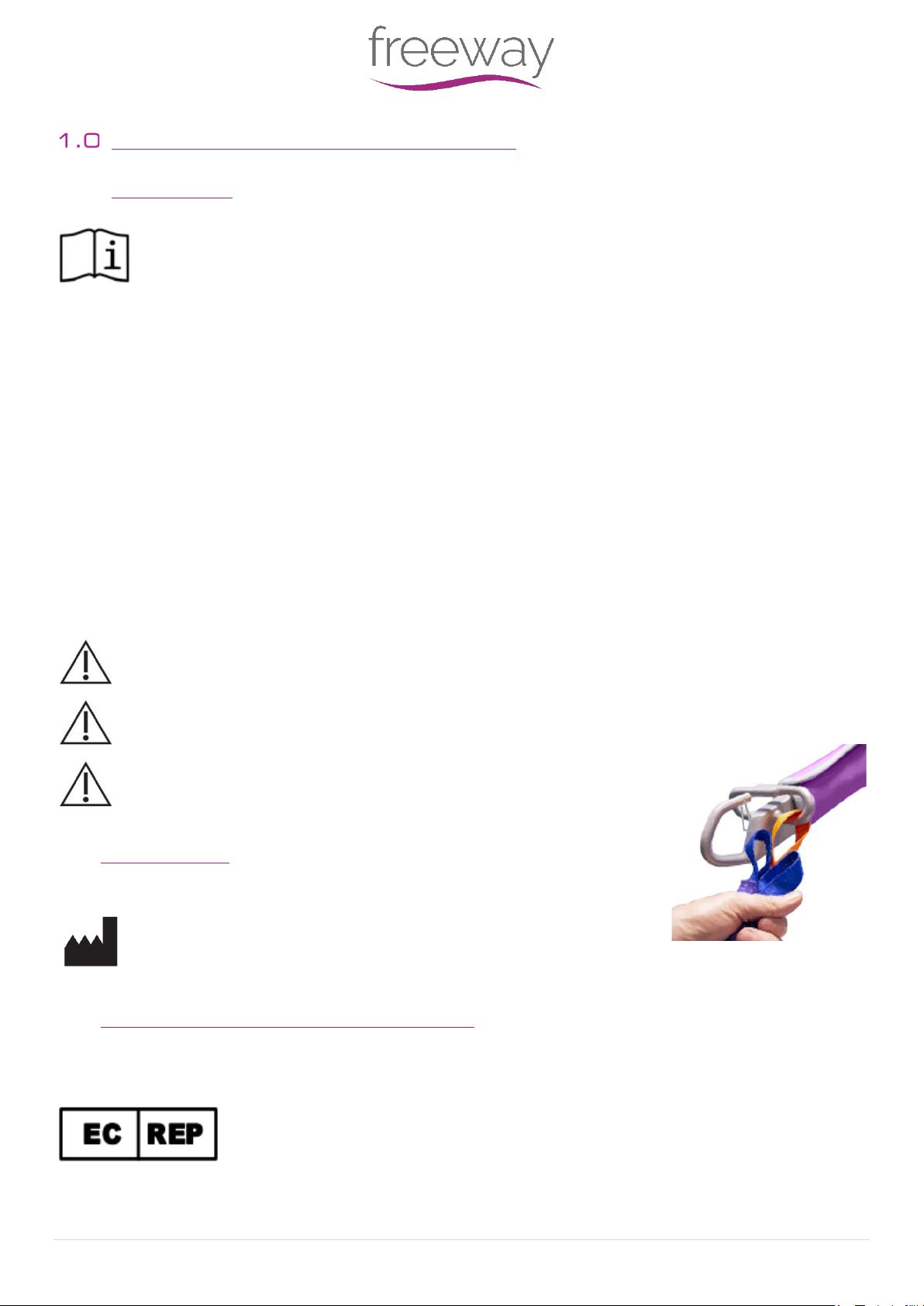
The Mobile Hoist is one of two components that makes this possible. The other component, the sling, is a specially designed
fabric accessory that attaches to the Hoist by means of a carry bar and straps, and holds the client during the lift/transfer.
Please refer to the user guides supplied with the sling and reference them while reviewing this manual.
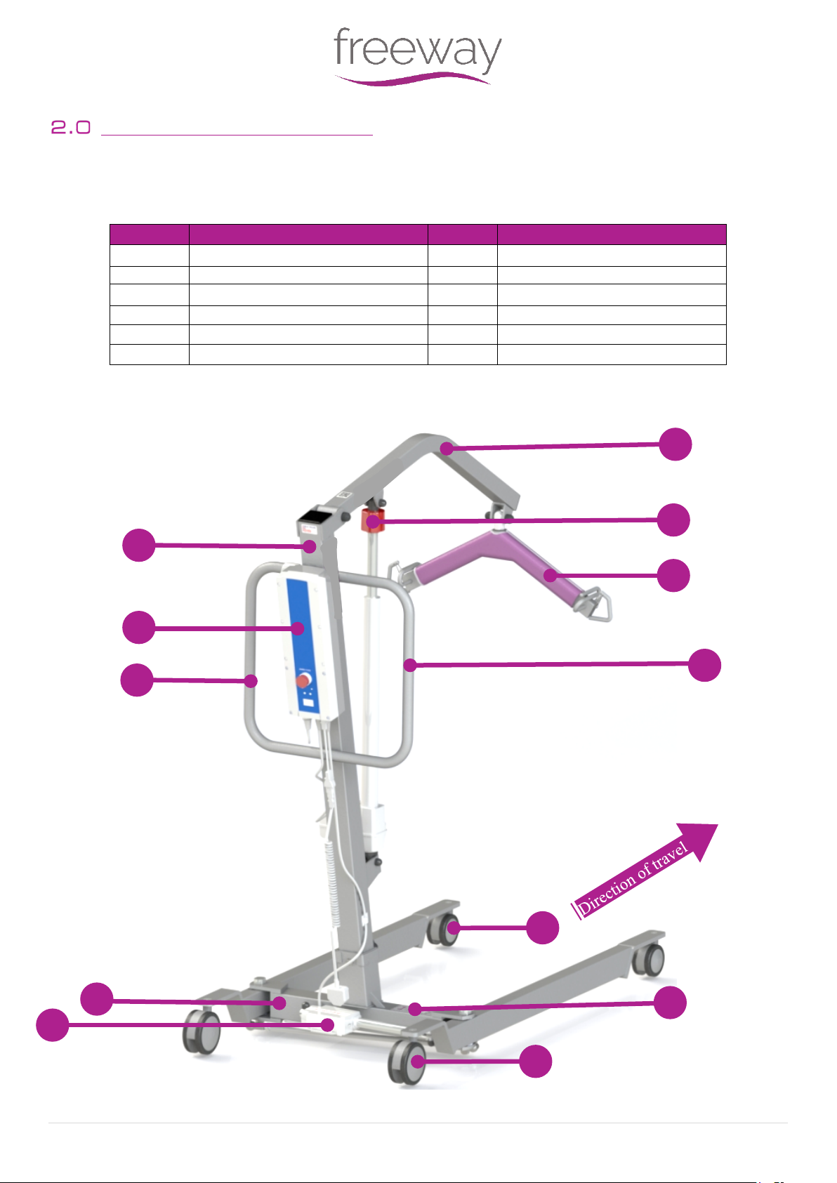
The functions of raising and lowering the boom, and opening and closing of the legs on the Hoist, are accomplished by pressing
buttons on the hand control. The hand control is attached to the Mobile Hoist.
The device is used under instruction, and the operation of the aid is undertaken by a trained carer.
A risk assessment must be performed before using any other manufactured slings or Mobile Hoist, to ensure safe
use can be established.
•The Freeway S180E Mobile Hoist is intended to be installed on a flat and levelled surface prior to use.
•The Hoist must be installed only by persons authorized by Prism Medical UK or who have the rights to install and
commission the Hoist safe for use.
•Under no circumstance should the Freeway S180E Mobile Hoist or entire system be put in control of a person who has
not been properly trained in the use and care of this equipment. Failure to adhere to this warning may result in serious
injury to the operator and/or the individual being transferred.
•In facilities where more than one operator will be responsible for using the Mobile Hoist and sling(s) it is imperative
that all such members be trained to use the Freeway S180E Mobile Hoist. A training program should be established by
the facility to acquaint new operators with this equipment.
•The Freeway S180E, and associated slings are not toys. Do not use it for unsafe practices. Do not allow children to play
with the Hoist or any of its components.
•Your guarantee is void if persons unauthorized by Prism Medical UK perform work on the Mobile Hoist.
•To maintain optimum function, the Freeway S180E Mobile Hoist should be inspected and maintained on a regular basis.
See section ‘General Inspection, Maintenance and Cleaning’ within this user manual.
•Any accessories used with this Mobile Hoist including belt(s), should be checked to ensure that they are in good
working order. Check for signs of wear to each component prior to use. Report any unusual wear, or damage
immediately to your local authorised dealer.

999367 – Revision B Page | 7 of 40
•The Freeway S180E Mobile Hoist and Slings(s) are intended only for transferring of a person. Prism Medical UK will not
be responsible for any damage caused by the misuse, neglect or purposeful destruction of the Unit, and/or its
associated components.
•The Mobile Hoist and its associated parts are certified to a maximum load of 180kg. Do not exceed the maximum rated
load of any of the components.
•Ensure that a clear space is maintained around the Mobile Hoist. Before performing a transfer, check for and move all
obstacles out of the way.
•Your product is for aiding and transferring a patient. Do not use it, or allow it to be used, for any other purpose.
•Protecting the people present, visually monitor the sling(s) loops connection points during transfer stages, so the belt
remains firmly attached to the clipped carry bar.
•In areas where children are prone to be present be vigilant when carrying out a transfer.
•To reduce the risk of unintended use, when the Hoist is not in use, remove the sling(s) from the product to prevent
entrapment or strangulation should the device be tampered with.
•Between Hoist, Spreader Bar and Body-Support Unit, the lowest maximum load shall always be used.
You may need to seek specialist advice on how to assist some people with specific moving and handling needs.
Sources of advice include, but is not limited to, professional bodies and organisations, occupational therapist,
physiotherapists, manual handling advisers and ergonomist with experience in health and social care.
1.7 Warning Notes
Your Freeway S180E Mobile Hoist has been manufactured and tested to exceed BS EN 10535:2006. This does not
mean that it can be used without care. ALL OPERATORS should have read the operating instructions and appreciate
this warning section.
1. ALL Mobile Hoists are less stable on sloping surfaces. A 5-degree slope is the maximum permitted and then only with
great care.
2. ALL Mobile Hoists are dangerous to the person being transferred when used recklessly or pushed at speed.
1.8 Operating Environment
The S180E Mobile Hoist is intended for use within the professional health care facility environment as well as the home health
care environment. The Hoist is not suitable for any other environment or special environments.
The Mobile Hoist is not intended to be used in environments where there are rapid changes in the environmental temperature
and humidity during intended use.

999367 – Revision B Page | 8 of 40
Components / Key Parts
Please see below to familiarise yourself with the components of the Freeway S180E Mobile Hoist. The image below show the
contents of the Hoist. If you have not received all the components contact Prism Medical UK dealer immediately – contact
details are provided on the last page of this manual.
Item
Description
Item
Description
1
Boom
6
Handle
2
Mast
7
Front Casters
3
Control Box & Battery
8
Leg Actuator
4
Manual Emergency lower
9
Base
5
Carry Bar /Carry Bar cover
10
Rear Casters
11
Serial Number/ Product Information
12
Lift Actuator
Figure 2
1
3
2
4
5
6
7
8
9
10
Table 2
11
12

999367 – Revision B Page | 9 of 40
Assembly instructions
3.1 Unpacking
Some of the parts are heavy and will need to be lifted with care. Items weighing over 20kg will require a two person
lift. Please refer to (7.0) technical specifications for components weights.
The Hoist will arrive to you in a robust box, please be careful when removing the components from the box. Please
read the user guide in full before operating.
This user manual should be kept safe for future reference.
The Hoist has been specifically designed to be installed in both the professional and home healthcare environments.
No matter the environment, health and safety factors should be considered to ensure the safety and essential performance of
the Hoist and to avoid unnecessary damage or injuries to people within the area of the Mobile Hoist.
The environment in which the Mobile Hoist is situated in, whilst carrying out a transfer, is required to be on a flat surface with
no steep inclines.
3.2 Unboxing Hoist
When using a sharp knife, be careful not to damage the product.
This section will summarise the layout of the Hoist Packaging and what is included in the Box. It is recommended a knife is used
for smoother unpacking of the Hoist. The Hoist is packed into a single box (750x450x400) weighing approximately 45kg.
Using a knife to open the box around the perimeter, the box should open, and the internal packaging must be removed to access
the Hoist. It will include all the following components. It is recommended that the components are removed in the numerical
order below.
1. Mast
2. Base
3. Fixings
4. Hand Control
5. Charging Lead
6. User Manual

999367 – Revision B Page | 10 of 40
3.3 Hoist Assembly
A. Carefully open the box and remove all loose parts and excess packaging from
the box.
2 person lift recommended for the following points.
B. Carefully holding onto the handle and boom, lift the Hoist components out of
the box.Place carefully onto the floor.
C. With one person lifting up from the front castors and one person lifting up
from the rear castors, raise the base from the box and place the Hoist base on
a flat surface and ensure the rear braked castors are locked.
D. Remove the Star Handle and bolt from the top of the base (as shown in Fig. 3).
E. Ensure all cables are clear from entrapment while fitting the base and mast
together. (As shown in Fig. 4).
Please ensure both hands are on the handles when lifting the mast into
position, possible risk of finger trap.
F. When the mast if fully engaged with the base, fit and fully tighten the Star
Handle and Bolt. (As shown in Fig. 5 and 6).
Ensure the mast is fully seated into the base and the Star Handle is in
position and tight before using the Hoist.
NOTE: To disassemble the Hoist into the two main sections (Mast/boom and Base)
simply follow the previous steps in reverse.
Figure 3
Figure 4
Figure 5
Figure 6

999367 – Revision B Page | 11 of 40
3.4 Electrical Connections
Connect all the cables to the control box as shown in the pictures
opposite.
A. Connect the lift actuator cable connector to the second port (marked No. 1)
from the left side of the control box (as shown in Fig. 7).
B. Connect the leg spreading actuator cable connector to the third port (marked
No. 2 in Fig. 8)
C. Connect the handset connector to the large port on the left side of the control
box. A locator pin on the plug ensures correct orientation of the connector (as
shown in Fig. 9).
D. Connect the mains cable/power cord to the control box (as shown in Fig. 10).
Ensure that all cables are located and secure before operating the Mobile
Hoist
Final Inspection
Before first operation of the Hoist:
•Confirm all cables are located and secure.
•Ensure the red emergency stop button on the control box is deactivated. (Rotate clockwise to release if required- Refer
to section 5.4 for guidance).
•Press the up button on the handset and confirm the actuator raises the boom.
•Press the down button on the handset and confirm the actuator lowers the boom.
•Press the button on the handset to operate the opening of the legs and confirm the actuator moves the legs outwards.
•Press the button on the handset to operate the closing of the legs and confirm the actuator moves the legs inwards.
•Press the red emergency stop button on the control box and check that actuators do not operate until the button is
reset. (See section 5.4 for guidance)
•Check the mechanical emergency lowering function works properly. (See section 5.5 for guidance)
•Check the rear castors brakes work properly.
•Check the battery pack is fully charged.
Your Hoist is now ready to use.
Figure 7
Figure 10
Figure 9
Figure 8

999367 – Revision B Page | 12 of 40
Figure 12
Figure 13
Figure 14
Figure 11
Operating instructions
The Mobile Hoist may be heavy for users and will need to be lifted with care, please operate the device with the use
of the castors wherever possible to prevent any injury.
Appropriate training in lifting and handling procedures should be undergone by any person operating the Mobile Hoist, for their
own and the client’s safety and comfort. These instructions are designed to cover the method of using the Mobile Hoist.
5.1 Manoeuvring the Hoist
A. To move the Hoist forward, hold onto the handle bar and push forward.
B. Do not stand on the leg actuator, or use the leg actuator to push the Hoist (Fig. 11 and 12).
C. When turning the Hoist, use both hands on the handle. Alternatively, it is possible to rotate the Hoist by applying the
brake to a single rear castor and rotating the Hoist about the braked castor. This movement should be performed with
a smooth, slow action to avoid swinging the patient unnecessarily.
D. The Freeway S180E Mobile Hoist has two rear castors with brakes.
E. The rear castors can be braked for rotation (by applying a single brake), lateral movement, and parking. To apply the
brake, press the brake pedal down with your foot (as shown in Fig. 13). To release the brake, press the raised pedal
towards the wheel (as shown in Fig. 14).
F. During lifting, the rear castors should remain locked to ensure that the Hoist will not move.
The castors should be locked if there is a risk of the Hoist driving into the patient. For example, when lifting the
patient from the floor.
5.2 Raising and Lowering
The up and down movement of the boom on the Freeway S180E Mobile Hoist is achieved by
an electric actuator which is controlled by hand control. The hand control has two buttons
with directional arrows up and down. The actuator stops automatically at the limit of travel in
both directions.
5.3 Open / Close Mobile Hoist Legs
The legs of Freeway S180E Mobile Hoist are opened/closed using the appropriate buttons
on the hand control, see figure 15 for guidance. The legs motion will be stopped
whenever the hand control button is released. The legs can be opened to enable access
around arm chairs or wheel chairs. When relocating the Mobile Hoist, manoeuvring
through narrow doorways and/or passages, the Mobile Hoist legs should be in the closed
position.
Figure 15
Figure 16

999367 – Revision B Page | 13 of 40
5.4 Emergency Stop Button
The Mackworth M440 Mobile Hoist is fitted with an Emergency Stop button.
Push the Emergency Stop button (as shown in Fig. 17) to cut all power to the Mobile
Hoist.
To resume power, release the emergency stop button by turning in a clockwise
direction (indicated by arrows on the Emergency Stop button) as shown in Fig. 18.
5.5 Emergency Lowering
5.5.1 Manual Emergency Lowering
In the case of power failure, it is possible to mechanically lower a patient suspended by
the Mackworth M440 Mobile Hoist.
Turn the manual lowering handle in clockwise direction (as shown in Fig. 19) to lower
the boom until the boom reaches a safe position.
The manual emergency lowering system should be used only if the
lowering procedures described in the previous section of the manual do
not work. Should you have any concerns or questions contact your local
authorised Mackworth Representative.
Do not use the Hoist after the manual lowering mechanism has been used.
The lift must be reset by a qualified technician after use. Contact your local
authorised Mackworth Service Provider.
5.5.2 Electrical Emergency Lowering
The Mobile Hoist Boom can be raised and lowered by pushing the emergency lifting and
lowering buttons on the control box with a suitable object, such as a pen nib or pencil (as
shown in Fig. 20).
5.6 Handset Operations
The Hand Controls has 4 functions: Up and Down, this will raise and lower the Mobile Hoist, and Legs Open
and Legs Close, these functions will open and close the legs.
Press down on each symbol to operate the desired function. It is not possible to use two functions at the same
time. Once the Mobile Hoist has reached the extent of its travel in a given direction, the actuator will
automatically stop, allowing you to then choose the opposite direction.
The handset is attached to the control box via a flexible, coiled cable that is secured in place with a friction-fit
plug. The coiled cable is designed to give the greatest number of options for carer positioning without having a
trailing cable around the patient. The handset also incorporates a hook which gives the carer flexibility whist
moving/positioning the patient. Clear and easy to understand labelling of the buttons enable ease of use for
the care giver.
The handset also displays battery level and service requirement by the use of LED lights.
Figure 17
Figure 18
Figure 19
Figure 21
Figure 20

999367 – Revision B Page | 14 of 40
5.6.1 Battery Status - Handset
5.6.2 Service Indication
The service indicator (Yellow LED) will blink when it is time for service. The standard setting is every 12 months/ 8000 cycles,
whichever comes first.
Indication
Comment
When it is time for service, the service indicator will remain illuminated 2 minutes after
use. Afterwards the control box will power down to save the battery.
When the service indicator lights up the system will still be functional.
Battery State
Indication
Comment
1
The battery is OK - no need for charging (100-50%) the third
LED is green
2
The battery needs to be charged (50-25%) the second LED is
yellow
3
The battery needs to be charged (less than 25%) The buzzer
sounds when a button is pressed
The first LED is yellow
4
The battery needs to be charged. Some of the functionality
of the lift is lost and it is only possible to drive the lifting arm
down.
By continuous use the diode blinks and starts to give an
audio signal
Table 4
Table 3

999367 – Revision B Page | 15 of 40
5.7 Battery
The battery pack should never be stored for long periods of time without a regular charge.
The battery pack is protected in an encased unit located on top of the control box, on the rear of the product. The control box,
below the battery, will inform the user when the battery is flat and requires charging, by an illuminated LED. An LED illuminate
when the battery needs recharging. Complete the lift and place the battery on charge.
5.7.1 Charging the battery pack
The battery pack can be recharged via mains lead (terminated with a
figure of eight plug)
A. Fit the mains lead figure of eight plug into charger link cable
(see Fig. 22).
B. Plug the 2-pin mains plug into a suitable mains outlet and
switch the mains supply on.
C. Charging is automatic and will normally take eight to twelve
hours to fully charge (from completely discharged state). You
cannot overcharge the battery pack if left for longer periods of
time.
D. To return the Hoist to use, switch off the mains supply.
Remove the plug from the socket and clip onto the Mast.
E. The Hoist is now ready for use.
5.7.2 Battery Status – Control Box
The Table below provides information on the four battery states seen on the Control Box LCD. Refer to this table when unsure of
what the symbols represent.
Battery State
Symbol
Comment
1
The battery is ok, no need for charging (100 - 50 %)
2
Battery needs charging (50 -25%)
3
Battery needs charging. (Less than 25%)
Buzzer sound is provided when a button is pressed in this battery
state.
4
The battery needs charging. At this stage some of the functionality
of the lift is lost. At this battery stage, it is not possible to drive the
lifting arm up or down. Furthermore, an audio signal will sound
when a control button is activated (17V or lower). The symbol will
switch between the two pictures for 10 seconds.
The battery symbol is shown when the box is active until power
down (2 minutes after use).
Figure 22
Table 5
Table 5

999367 – Revision B Page | 16 of 40
5.8 Control Box Display
The Table below provides information on all Symbols seen on the Control Box display and what they represent. Refer to this
table when unsure of a Symbol displayed on the Control Box.
5.8.1 Service Information read-out:
Basic service information can be read out on the display. To display the service information on the display press the lifting arm
up button (Only for ½ second press). The information (below) will be shown for ½ minute or until other buttons are activated.
If “No Days” are chosen for service internal then the display will show Days since last service.
Control Box
Feature
Symbol
Comment
Charging of battery
When the mains cable is plugged in and a control button is activated
the symbol to the left is shown on the display until power down 2
minutes later. The purpose if the symbol is to inform the user that it
is not possible to use the lift when it is plugged into the mains.
Short Circuit
If there is a short circuit, the control box will show the short circuit
symbol with a recommendation to check the connections. This
symbol will be shown until the short circuit has been repaired.
Service
The control box will show the service symbol when it is time for
service. The standard settings is after 12 months/8000 cycles. After
each power down, first time that the symbol (100 milli-seconds) so
that the user gets a reminder about checking the display.
The 'SERVICE' Text will blink 3 times, then a static service symbol will
be shown (10 seconds in total). Even though it is time for service the
system will still be functional and work as normal.
Overload channel 1
only:
When Overload occurs (according to the pre-defined current cut-off
limit) the overload symbol will be shown on the display. The 'MAX.
Text will blink 3 times and the overload symbol will be shown for 10
seconds in total.
Table 6

999367 – Revision B Page | 17 of 40
5.9 Slings
The Freeway S180E is designed to be used in combination with a Sling to perform its intended use. The sections below include
the correct and safe manor of attaching/detaching the Slings as well as a list of approved slings for use.
5.9.1 Sling Attachment/Detachment
Sling loops should be attached as follows:
1. Put the required sling loop onto your finger and thumb and then using the same finger or thumb, pull back the spring
locking mechanism on the correct hook on the correct side of the carry bar (Figure 23).
2. Slide the sling loop from your finger and thumb over the edge of the hook (Figure 24).
3. After positioning the loop below the locking mechanism (Figure 25) release the spring locking mechanism to secure the
sling loop (Figure 26).
To remove the sling, simply reverse the process – pull back on the spring locking mechanism, lift the loop out of the hook and
release the locking mechanism.
The same process of attaching and detaching the Sling is relevant for the QRS (Quick Release System) Carry Bar.
5.9.2 Compatible Slings
Below is a list of slings that are recommended and have been approved by Prism Medical UK for use in combination with the
product.
We recommend the use of the Mackworth Healthcare or Care-Ability manufactured sling range (type ‘BF’ applied part) to be
utilised with the Freeway S180E Mobile Hoist. It is at the user’s discretion to use alternative supplied product. In utilising
another manufacturer’s sling, checks must first be made to ensure the sling is safe to use and meets the requirements of BS EN
ISO 10535 before its use.
The slings with a safe working load of 180kg that can be used with the Freeway S180E Mobile Hoist are shown below in Table’s 7
and 8, complete with product codes. For all components, the lowest maximum safe working load must always be adhered to.
Figure 27
Figure 28
Figure 29
Figure 23
Figure 24
Figure 25
Figure 26

999367 – Revision B Page | 18 of 40
Size
Mackworth Sling Range - Product Material and Code
Polyester Solid
Polyester Mesh
Parasilk
Quilted
Supersoft Spacer
Mackworth Oak
Small
1201OK7500
1201OK8500
1201OK3500
1201OK5500
1201OK4500
Medium
1201OK7400
1201OK8400
1201OK3400
1201OK5400
1201OK4400
Large
1201OK7300
1201OK8300
1201OK3300
1201OK5300
1201OK4300
XL
1201OK7200
1201OK8200
1201OK3200
1201OK5200
1201OK4200
XXL
1201OK7100
1201OK8100
1201OK3100
1201OK5100
1201OK4100
XXXL
1201OK7000
1201OK8000
1201OK3000
1201OK5000
1201OK4000
Mackworth Oak with head support
Small
1201OK7520
1201OK8520
1201OK3520
1201OK5520
1201OK4520
Medium
1201OK7420
1201OK8420
1201OK3420
1201OK5420
1201OK4420
Large
1201OK7320
1201OK8320
1201OK3320
1201OK5320
1201OK4320
XL
1201OK7220
1201OK8220
1201OK3220
1201OK5220
1201OK4220
XXL
1201OK7120
1201OK8120
1201OK3120
1201OK5120
1201OK4120
XXXL
1201OK7020
1201OK8020
1201OK3020
1201OK5020
1201OK4020
Mackworth Yew
Small
1201YW7500
1201YW8500
1201YW3500
n/a
1201YW4500
Medium
1201YW7400
1201YW8400
1201YW3400
n/a
1201YW4400
Large
1201YW7300
1201YW8300
1201YW3300
n/a
1201YW4300
XL
1201YW7200
1201YW8200
1201YW3200
n/a
1201YW4200
XXL
1201YW7100
1201YW8100
1201YW3100
n/a
1201YW4100
XXXL
1201YW7000
1201YW8000
1201YW3000
n/a
1201YW4000
Mackworth Yew with head support
Small
1201YW7520
1201YW8520
1201YW3520
n/a
1201YW4520
Medium
1201YW7420
1201YW8420
1201YW3420
n/a
1201YW4420
Large
1201YW7320
1201YW8320
1201YW3320
n/a
1201YW4320
XL
1201YW7220
1201YW8220
1201YW3220
n/a
1201YW4220
XXL
1201YW7120
1201YW8120
1201YW3120
n/a
1201YW4120
XXXL
1201YW7020
1201YW8020
1201YW3020
n/a
1201YW4020
Mackworth Hazel
Small
1201HZ7500
1201HZ8500
1201HZ3500
1201HZ5500
1201HZ4500
Medium
1201HZ7400
1201HZ8500
1201HZ3400
1201HZ5400
1201HZ4400
Large
1201HZ7300
1201HZ8300
1201HZ3300
1201HZ5300
1201HZ4300
XL
1201HZ7200
1201HZ8200
1201HZ3200
1201HZ5200
1201HZ4200
XXL
1201HZ7100
1201HZ8100
1201HZ3100
1201HZ5100
1201HZ4100
XXXL
1201HZ7000
1201HZ8000
1201HZ3000
1201HZ5000
1201HZ4000
Mackworth Hazel with head support
Small
1201HZ7520
1201HZ8520
1201HZ3520
1201HZ5520
1201HZ4520
Medium
1201HZ7420
1201HZ8520
1201HZ3420
1201HZ5420
1201HZ4420
Large
1201HZ7320
1201HZ8320
1201HZ3320
1201HZ5320
1201HZ4320
XL
1201HZ7220
1201HZ8220
1201HZ3220
1201HZ5220
1201HZ4220
XXL
1201HZ7120
1201HZ8120
1201HZ3120
1201HZ5120
1201HZ4120
XXXL
1201HZ7020
1201HZ8020
1201HZ3020
1201HZ5020
1201HZ4020
Mackworth Willow
Small
1201WL7500
This sling is made up of a single quilted material backed with solid
polyester material.
Medium
1201WL7400
Large
1201WL7300

999367 – Revision B Page | 19 of 40
XL
1201WL7200
XXL
1201WL7100
XXXL
1201WL7000
Mackworth Willow with head support
Small
1201WL7520
This sling is made up of a single quilted material backed with solid
polyester material.
Medium
1201WL7420
Large
1201WL7320
XL
1201WL7220
XXL
1201WL7120
XXXL
1201WL7020
Mackworth Beech
Small
1201BC7500
1201BC8500
1201BC3500
1201BC5500
1201BC4500
Medium
1201BC7400
1201BC8400
1201BC3400
1201BC5400
1201BC4400
Large
1201BC7300
1201BC8300
1201BC3300
1201BC5300
1201BC4300
XL
1201BC7200
1201BC8200
1201BC3200
1201BC5200
1201BC4200
XXL
1201BC7100
1201BC8100
1201BC3100
1201BC5100
1201BC4100
XXXL
1201BC7000
1201BC8000
1201BC3000
1201BC5000
1201BC4000
Mackworth Beech with head support
Small
1201BC7520
1201BC8520
1201BC3520
1201BC5520
1201BC4520
Medium
1201BC7420
1201BC8420
1201BC3420
1201BC5420
1201BC4420
Large
1201BC7320
1201BC8320
1201BC3320
1201BC5320
1201BC4320
XL
1201BC7220
1201BC8220
1201BC3220
1201BC5220
1201BC4220
XXL
1201BC7120
1201BC8120
1201BC3120
1201BC5120
1201BC4120
XXXL
1201BC7020
1201BC8020
1201BC3020
1201BC5020
1201BC4020
Mackworth Pine
Small
1201PN7500
1201PN8500
1201PN3500
1201PN5500
1201PN4500
Medium
1201PN7400
1201PN8400
1201PN3400
1201PN5400
1201PN4400
Large
1201PN7300
1201PN8300
1201PN3300
1201PN5300
1201PN4300
XL
1201PN7200
1201PN8200
1201PN3200
1201PN5200
1201PN4200
XXL
1201PN7100
1201PN8100
1201PN3100
1201PN5100
1201PN4100
XXXL
1201PN7000
1201PN8000
1201PN3000
1201PN5000
1201PN4000
Mackworth Pine with head support
Small
1201PN7520
1201PN8520
1201PN3520
1201PN5520
1201PN4520
Medium
1201PN7420
1201PN8420
1201PN3420
1201PN5420
1201PN4420
Large
1201PN7320
1201PN8320
1201PN3320
1201PN5320
1201PN4320
XL
1201PN7220
1201PN8220
1201PN3220
1201PN5220
1201PN4220
XXL
1201PN7120
1201PN8120
1201PN3120
1201PN5120
1201PN4120
XXXL
1201PN7020
1201PN8020
1201PN3020
1201PN5020
1201PN4020
Size
Care-Ability Sling Range - Product Material and Code
Polyester
Mesh
Spacer
Parachute
CA300 Universal
P1
CA300PP1
CA300MP1
CA300SP1
CA300PAP1
P2
CA300PP2
CA300MP2
CA300SP2
CA300PAP2
P3
CA300PP3
CA300MP3
CA300SP3
CA300PAP3
P4
CA300PP4
CA300MP4
CA300SP4
CA300PAP4
P5
CA300PP5
CA300MP5
CA300SP5
CA300PAP5
Table 7

999367 – Revision B Page | 20 of 40
X Small
CA300PXS
CA300MXS
CA300SXS
CA300PXS
Small
CA300PS
CA300MS
CA300SS
CA300PAS
Small/Medium
CA300PSM
CA300MSM
CA300SSM
CA300PASM
Medium
CA300PM
CA300MM
CA300SM
CA300PAM
Medium/Large
CA300PML
CA300MML
CA300SML
CA300PAML
Large
CA300PL
CA300ML
CA300SL
CA300PAL
X Large
CA300PXL
CA300MXL
CA300SXL
CA300PAXL
CA400 Universal Deluxe
P1
CA400PP1
CA400MP1
CA400SP1
CA400PAP1
P2
CA400PP2
CA400MP2
CA400SP2
CA400PAP2
P3
CA400PP3
CA400MP3
CA400SP3
CA400PAP3
P4
CA400PP4
CA400MP4
CA400SP4
CA400PAP4
P5
CA400PP5
CA400MP5
CA400SP5
CA400PAP5
X Small
CA400PXS
CA400MXS
CA400SXS
CA400PAXS
Small
CA400PS
CA400MS
CA400SS
CA400PAS
Small/Medium
CA400PSM
CA400MSM
CA400SSM
CA400PASM
Medium
CA400PM
CA400MM
CA400SM
CA400PAM
Medium/Large
CA400PML
CA400MML
CA400SML
CA400PAML
Large
CA400PL
CA400ML
CA400SL
CA400PAL
X Large
CA400PXL
CA400MXL
CA400SXL
CA400PAXL
CA500 Toilet Access
P1
CA500PP1
CA500MP1
CA500SP1
CA500PAP1
P2
CA500PP2
CA500MP2
CA500SP2
CA500PAP2
P3
CA500PP3
CA500MP3
CA500SP3
CA500PAP3
P4
CA500PP4
CA500MP4
CA500SP4
CA500PAP4
P5
CA500PP5
CA500MP5
CA500SP5
CA500PAP5
X Small
CA500PXS
CA500MXS
CA500SXS
CA500PAXS
Small
CA500PS
CA500MS
CA500SS
CA500PAS
Small/Medium
CA500PSM
CA500MSM
CA500SSM
CA500PASM
Medium
CA500PM
CA500MM
CA500SM
CA500PAM
Medium/Large
CA500PML
CA500MML
CA500SML
CA500PAML
Large
CA500PL
CA500ML
CA500SL
CA500PAL
X Large
CA500PXL
CA500MXL
CA500SXL
CA500PAXL
CA501 Toilet Access with crossover straps
P1
CA501PP1
CA501MP1
CA501SP1
CA501PAP1
P2
CA501PP2
CA501MP2
CA501SP2
CA501PAP2
P3
CA501PP3
CA501MP3
CA501SP3
CA501PAP3
P4
CA501PP4
CA501MP4
CA501SP4
CA501PAP4
P5
CA501PP5
CA501MP5
CA501SP5
CA501PAP5
X Small
CA501PXS
CA501MXS
CA501SXS
CA501PAXS
Small
CA501PS
CA501MS
CA501SS
CA501PAS
Small/Medium
CA501PSM
CA501MSM
CA501SSM
CA501PASM
Medium
CA501PM
CA501MM
CA501SM
CA501PAM
Other manuals for S180E Mobile Hoist
1
Table of contents
Other FREEWAY Medical Equipment manuals

FREEWAY
FREEWAY MT400-24T Assembly instructions

FREEWAY
FREEWAY Height Adjustable Shower Trolley with Liner... User manual

FREEWAY
FREEWAY Transactive Xtra 130 User manual

FREEWAY
FREEWAY S180E Mobile Hoist User manual

FREEWAY
FREEWAY 999037 User manual

FREEWAY
FREEWAY FMT724M User manual

FREEWAY
FREEWAY S180 Mobile User manual