Friant MY-HITE User manual

MY-HITE POWERBEAMMANUAL
friant.com

My-Hite Power Beam Installation Manual
2 3
MY-HITE POWER BEAM INSTALLATION MANUAL
Post & Foot Installation �������������������������������������������������������������������������������������������� 8
Beam Installation ��������������������������������������������������������������������������������������������������������� 9
Glass or Fabric Panel Installation on Top Cap ���������������������������������������������� 10
Top Cap Installation �������������������������������������������������������������������������������������������������� 12
Festoon Installation ��������������������������������������������������������������������������������������������������� 13
TBD Installation ����������������������������������������������������������������������������������������������������������� 14
Short Cover Installation ������������������������������������������������������������������������������������������� 16
Shelves & Overhead Storage �������������������������������������������������������������������������������� 17
Tall Cover Installation ������������������������������������������������������������������������������������������������ 17
Beam Cover & Data Panel Installation ��������������������������������������������������������������18
Arc Side Panel Installation ������������������������������������������������������������������������������������� 19
Corner Trim & Interior Column Top Cap Installation ������������������������������� 20
Finished Installation 21

My-Hite Power Beam Installation Manual
4 5
GENERAL INFORMATION
This installation manual provides necessary information for the
safe installation of Friant’s Power Beam product.
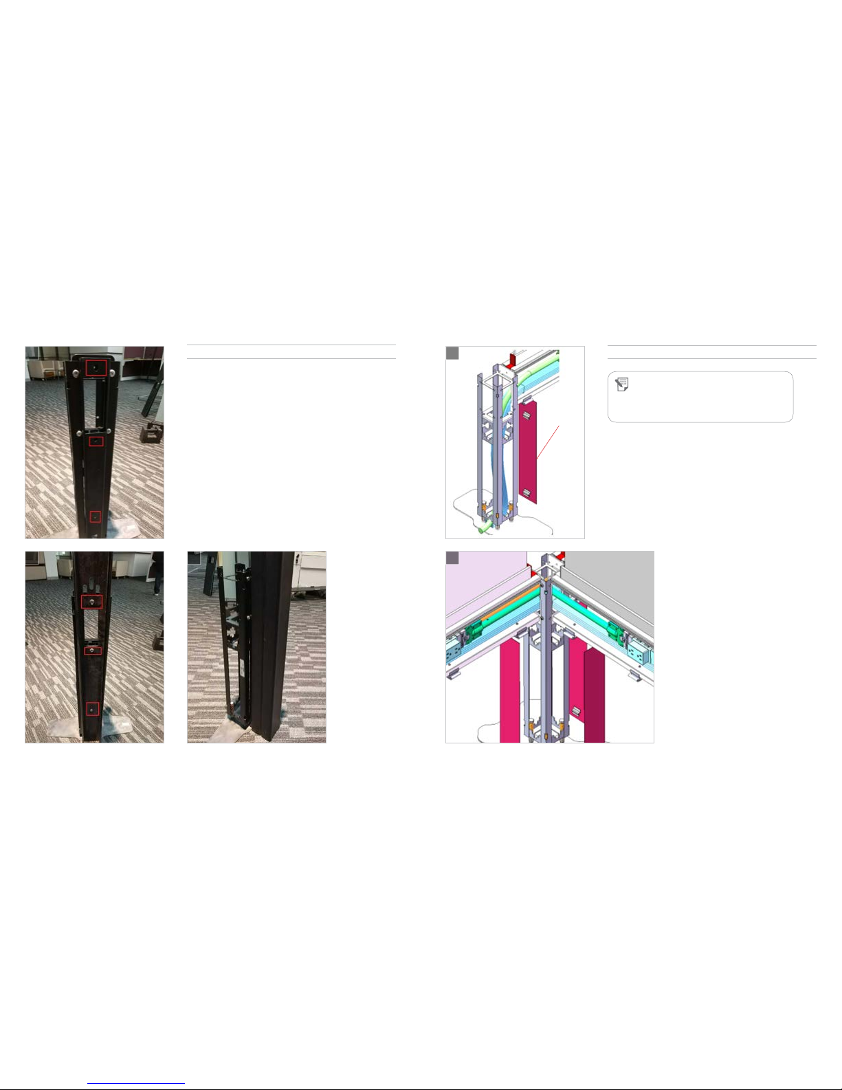
The Friant Power Beam is a modular power and data delivery system
comprised of posts, beams, feet, beam covers, post covers and
data covers, with additional potential for accessories such as fabric
covered screns or glass screens� It consists of some products that are
factory assembled and require installation only, and some that require
assembly during the installation process�
It is the responsiblity of the dealer and the installer to properly
install this product according to this manual and generally accepted
industry practices�
WARNING: Failure to follow
the instructions in this manual
can result in product damage,
personal injury or both.
SAFETY & SUPPORT
SUPPORT CENTER
Should you have any questions or require
assistance during the installation process,
please telephone our support center:
PHONE (510) 535-5113
HOURS Monday - Friday, 8am - 5pm PST
Download additional copies of this installation
manual at www.friant.com/install.
SAFETY NOTES
Please read all WARNINGS and NOTES, as these are for
your safety�
Please read TIPS in the installation as helpful
suggestions�
Always use proper tools when installing�
Keep your work area clean, clutter-free and safe
during installation�
Use eye protection when working under a
workstation or when working with tools�
Many products weigh more than 35 pounds� Use
two or more people to safely lift, carry and install
the products�
When using tools, extension cords or ladders, use
them in accordance to OSHA guidelines�
Work safe, work smart�
GENERAL INFORMATION
INSTALLATION TOOLS
INSTALLATION TOOLS
STAGING
In an effort to make your project run more
smoothly, the following is recommended:
Unload all products into a staging area on your
job site and sort by product number�
Check in and count all products for accuracy
and damage prior to the delivery truck leaving�
Note any damages or shortages on the Bill of
Lading before signing�
Notify the factory immediately of any shortages
or damages (with photo to document)�
Keep and maintain a clutter-free staging area —
it will help speed up your assembly�
Protect all building walls with furniture pads
or cardboard where product is leaning against
them or in high traffic areas�
FOR SUCCESSFUL INSTALLATION
Keep these items in mind while installing product:
Verify that all products are level and correctly
attached�
STAGING & INSTALLATION
The following tools are necessary for field
assembly and installation of Friant’s My-Hite
Power Beam product:
#3 Phillips head screwdriver
5mm Allen Key Bit
1/2” Open End Wrench
1/2” Socket Wrench
1/4” Hand Driver for Socket

My-Hite Power Beam Installation Manual
6 7
POST & FOOT INSTALLATION
1. Attach (1) column to (1) foot using (4) M8x80 hex bolt, (4)
16x45 brown springs, and (4) nuts� IMAGE A
A
B
C
Tools needed: (4)M8x80 hex bolt, (4) 16x45 brown springs,
(4) nuts, straight wrench.
NOTE: Make sure bolt does not go through
the base plate. It should not extrude on the
bottom side.
NOTE: Make sure that column is at 90° degrees to
the foot and that the top of column is level when
tightening the hex bolts and nuts.
2. Tighten the hex bolts and nuts using a hex wrench and
straight wrench, to secure and level the column� IMAGE B
3. Repeat procedure with other columns� IMAGE C
Hex Bolt
Spring
Nuts

My-Hite Power Beam Installation Manual
8 9
GLASS OR FABRIC PANEL INSTALLATION ON TOP CAPBEAM INSTALLATION
BEAM INSTALLATION
1. Slide beam into position at top and inside of columns as
shown� IMAGE A
2. Using (4) M6x12 hex flat head screws, attach the beam to
the column� Secured beam shown� IMAGE B
3. Repeat on other column� IMAGE C
4. Assembled foot, column, and beam construction� IMAGE D
A
B C
D
1. Position two brackets at the bottom of the glass or fabric
panel as shown� IMAGE A
2. Secure the brackets to the glass panel using (2) M6x16
screws per bracket (4 total)� IMAGE B
3. Slide the glass and brackets into top cap track as shown�
IMAGE C
4. Insert (2) end caps to the top cap on both sides� IMAGE D
5. Install the Hex flat head screw to the center hole on
the underside of the top cap to prevent the panel from
moving� IMAGE E
6. Secure the top cap to the beam with (8) M6x28 socket cap
screws (step 6), 5mm Allenhead screws� IMAGE F
INSTALLATION OF TOP CAP WITH SCREEN SUPPORT
A
B
C D
E F
Hex Flat
Head Screw
Top
Cap
Underside
of frame
Underside
of top cap
Inside of
column

My-Hite Power Beam Installation Manual
10 11
TOP CAP INSTALLATIONGLASS OR FABRIC PANEL INSTALLATION ON TOP CAP
INSTALLATION OF TOP CAP WITH SCREEN SUPPORT
CONTINUED
G
H
7. Installed screen, then top cap� IMAGE G
8. Finished installation� IMAGE H
INSTALLATION OF TOP CAP WITHOUT SCREEN SUPPORT
1. Secure top cap to the beam with (8) M6x28 socket cap
screws (4 on each side of the beam)� IMAGE A
2. Install other top caps to the beams in the same manner�
Socket cap screws, 5mm Allenhead� IMAGE B
3. Finished installation� IMAGE C
A
B
C
Screen
Top Cap

My-Hite Power Beam Installation Manual
12 13
BEAM POWER POLE INSTALLATIONFESTOON INSTALLATION
FESTOON INSTALLATION
1. Layout of 180 degree� IMAGE A
2. Layout of 90 degree L shape� IMAGE B
A
180° Layout
90° Layout
B
BEAM POWER POLE INSTALLATION
1. Insert one small beam attachment plate to the post� There
are two bulges and two threaded mounting holes on the
small beam to secure the U piece� IMAGE A
2. Secure the small beam attachment plate with 4 screws�
IMAGE B
3. Attach one long panel to the post� IMAGE C
A
B C
Long Panel
Small Beam
Attachment
Plate

My-Hite Power Beam Installation Manual
14 15
SHORT COVER INSTALLATIONBEAM POWER POLE INSTALLATION
4. There are three mounting holes on the U piece� The two
holes above are through holes corresponding the two
mounting holes on the small beam� The one hole below is
threaded hole to secure the U piece� IMAGE D
5. Use three screws to secure the U piece to the small beam
through the long panel� IMAGE E
6. Secure the two U pieces� IMAGE F
BEAM POWER POLE INSTALLATION
D
E F
SHORT COVER INSTALLATION
1. Place short covers into positions on columns and slide
down to lock into place� Short covers are used on columns
below where beams attach to columns� IMAGE A & B
A
B
Short Cover
NOTE: Short covers have two hooks on the
backside. Place the short covers into position and
slide down slightly to lock them into place. Short
covers are used on columns that are in the middle
of installations that do NOT have a beam in place.

My-Hite Power Beam Installation Manual
16 17
BEAM COVER & DATA PANEL INSTALLATIONTALL COVER INSTALLATION
TALL COVER INSTALLATION
1. Install the tall cover to the side post� IMAGE A
2. Install the tall cover to the middle post� IMAGE B
A
B
Tall Cover
BEAM COVER & DATA PORT PLATE INSTALLATION
1. Place beam cover in position and push gently to snap into
place� IMAGE A
2. Snap data port plate (not shown) into place�
A
NOTE: The beam cover must be installed before
installing the arc side panel and the hanging bars.
Beam Cover
Beam
Cover Clips
NOTE: Tall covers have three hooks on the
backside. Place the tall covers into position and
slide down slightly to lock them into place. Tall
covers are used on columns that are in the middle
of installations that do NOT have a beam in place.
They are NOT used on columns on the ends of
beam installations.

My-Hite Power Beam Installation Manual
18 19
CORNER TRIM & INTERIOR COLUMN TOP CAP INSTALLATIONARC SIDE PANEL INSTALLATION
NOTE: They have two hooks on the back:
Place bottom hook into slot, slide down & push
gently on the top of Arc Side panel, and it will click
into place.
ARC SIDE PANEL INSTALLATION
1. Arc side panels are applied to long column sides on the
ENDS OF INSTALLATIONS, not in the middle� IMAGE A
A
B
End Column
Top Cap
Arc Side
Panel 2. Once arc side panels are in place, align end column
top cap over top of end column, making sure tabs on
underside of the top cap are in the proper place� Push
down gently till top cap clicks into place� IMAGE B
CORNER TRIM & INTERIOR COLUMN
TOP CAP INSTALLATION
1. Clip corner trim to the sides of the long covers in the
middle columns on installations as shown� IMAGE A
A
B
WARNING: Do NOT use corner trim
on columns on the ends of beam
installations.
2. To install interior column top cap: align top cap over top of
column, making sure tabs on underside of the top cap are
in the proper place� Push down gently till top cap clicks
into place� IMAGE B
Interior Column
Top Cap
Corner Trim

20
FINISHED INSTALLATION
1. Layout of a finished installation� IMAGE A
A
042517
4901 EAST 12th St / Oakland / California 94601 / T: 510.535.5113 / F: 510.535.5237 / friant.com
Other manuals for MY-HITE
1
Table of contents
Other Friant Office Equipment manuals
Popular Office Equipment manuals by other brands

IAC INDUSTRIES
IAC INDUSTRIES SMS S1 SMART MOBILE STATION Assembly instructions

Dorel
Dorel 63001BLK1E Assembly manual

Ergotron
Ergotron Anthro-DNA Steve's Station Essential Assembly instructions

Steelcase
Steelcase Migration SE Boundary Screen quick start guide

Teknion
Teknion LEDGER PLUS Installation guides

Reiner
Reiner jetStamp graphic 970 operating manual