manuals.online logo
Brands
  1. Home
  2. •
  3. Brands
  4. •
  5. Fright Ideas
  6. •
  7. Controllers
  8. •
  9. Fright Ideas PicoBoo JR User manual

Fright Ideas PicoBoo JR User manual

REC 1 2
Recording Animation
Troubleshooting
Quick-Start Guide
Power Supply
PicoBoo JR
NEED HELP?
There are videos available online at
help.frightideas.com/103
Previewing your Scare
Write-Protecting Your Audio and Animation
The write-protect setting can be toggled on or off by powering up the PicoBoo while holding the 2 button. When
the red light flashes a few times the write-protect has been toggled.
Leaving an Output On when Animation Completes
Escape Rooms often need an output to stay on after the animation finishes playing. To do this, hold the output’s
button as you are tapping REC to stop recording. The output(s) will stay on indefinitely. To turn them off tap the
1 button, or re-trigger the controller to restart the scene.
Recording Animation
The PicoBoo JR can record up to 4 minutes of animation.
Sizing your Power Supply
Your PicoBoo’s power supply must be 12 volts
DC. The wattage you’ll need will vary if you’re
trying to power other devices from the same
supply.
Add up the wattage of all the devices that will
be used at the same time and make sure your
power supply’s wattage is equal to or higher
than that number. Use 2 watts for the PicoBoo.
Example:
2 watts PicoBoo
+ 6 watts 1 x 12VDC 6 watt solenoids
= 8 watts Total - Need at least 8 watts
Factory Reset
If at any point you want to start from scratch, power up while holding the REC button for 10 seconds to factory reset.
The yellow IN light is flashing or throbbing and the PicoBoo won’t trigger.
The PicoBoo is currently ignoring the trigger. It does this at startup to allow a PIR motion sensor to warm up, or
anytime a triggered scene is cancelled by pressing the 2 button. It will resume normal operation shortly.
The REC button is not responding. Can’t record animation.
• The PicoBoo may be write-protected. See Write-Protecting Your Audio and Animation above.
Don’t see your problem here? Check our website for more information.
REC 1 2 REC 1 2
TAP RECORD TO
START RECORDING
TAP RECORD TO
STOP RECORDING
ANIMATE THE RELAYS
USING THE 1 & 2 BUTTONS
REC 1 2
TAP 2 TO CANCEL
PLAYBACK
REC 1 2
THE REC LIGHT WILL BLINK
AS YOUR SCARE PLAYS
REC 1 2
TAP 2 TO START
PLAYING THE SCARE
POWER CAN BE SUPPLIED USING
THE BARREL CONNECTOR OR THE TRIGGER
TERMINAL BLOCK.
C CNO NONC NC
RELAY OUTPUTS
-
+
+
-
POWER / INPUT
12 VDC
5A MAX
10A 250VAC, 5A 30VDC EACH
IN
PIR
SW
NPN
1 2
C CNO NONC NC
RELAY OUTPUTS
-
+
+
-
REC 2
POWER / INPUT
PWR IN
1
12 VDC
5A MAX
WWW.FRIGHTIDEAS.COM
PICOBOO JR
PROP CONTROLLER
103s
NEED HELP?
INPUT
DISABLED
10A 250VAC, 5A 30VDC EACH
?
VISIT HELP.FRIGHTIDEAS.COM/103
IN
TAP 2
TO PLAY
PIR
SW
NPN
1 2
Trigger Input Wiring
Relay Output Wiring
PRESSURE MAT
PUSH BUTTON
SWITCH
TO TRIGGER
PIR MOTION SENSOR
BEAM SENSOR
PRESSURE MAT OR PUSHBUTTON
CONTINUOUS PLAY (LOOPED)
BLUE
BROWN
WHITE
BLACK
GND (-)
12VDC (+)
RELAY C
RELAY N.O.
SENSOR WIRES
BLACK
RED
WHITE
GREEN
GND (-)
12VDC (+)
RELAY C
RELAY N.O.
SENSOR WIRES
C
N.O.
+
-
WIRELESS TRIGGER
NOTE: PIR SENSORS CAN TAKE UP TO A
MINUTE TO “WARM UP”. DURING THIS TIME
THE PICOBOO’S YELLOW INPUT LIGHT WILL
FLASH.
RELAY
OUTPUT
MULTIPLE PICOBOOS WITH ONE TRIGGER
CONNECT THE TRIGGER AS
SHOWN IN ONE OF THE
OTHER DIAGRAMS.
CONNECT ADDITIONAL
PICOBOOS TO THE FIRST
PICOBOO AS SHOWN.
ADDITIONAL
PICOBOO
LOOPED
LOOPED WITH
ON/OFF OPTION
FIRST
PICOBOO
BASE STATION
REMOTE
CONNECT THESE ONLY
IF THE BASE RUNS ON
12 VDC AND DOES NOT
HAVE ITS OWN POWER
SUPPLY CONNECTED.
By default, the animation will play once
when the trigger is activated. If the trigger is
still active when the animation ends it will
loop. Enable “Single Shot” mode if you
want to prevent looping.
Toggling Single Shot Mode
1. Hold the middle 1 button while powering up the PicoBoo.
2. Keep holding the 1 button for about 10 seconds until the
light above it comes on and stays on, then let go.
Repeat the same steps to disable.
POWER
!
• Each output can handle up to 10 amps at 120VAC, 5 amps at 220VAC, or 5 amps at 30 VDC.
• The terminal blocks can be removed by pulling them out in the direction the wires exit the block.
• If you’d like the device to stay on by default and turn off when the output is energized use NC instead of NO.
!
!
12 VDC
DEVICE
ANY 12 VDC DEVICE
ONE 110 VOLT DEVICE, ONE 12 VDC DEVICE
ANY VOLTAGE
DEVICE
ANY DEVICE THAT’S NOT 12 VDC
12 VDC MOTOR ON/OFF IN ONE DIRECTION
FOG
FOG MACHINE
ANY 110 VOLT LOAD
TO POWER SUPPLY
APPROPRIATE
FOR DEVICE
TAKE APPROPRIATE
SAFETY PRECAUTIONS
WHEN WIRING HIGH
VOLTAGES.
12 VDC MOTOR FORWARD AND REVERSE
TO WALL
OUTLET
TO WALL
OUTLET
USE A 12V 5A POWER
SUPPLY FOR THE
PICOBOO.
USE A 12V 5A POWER
SUPPLY FOR THE
PICOBOO.
BLUE = FAST
GREEN = SLOW
HIGH
VOLTAGE
BLUE = FAST
GREEN = SLOW
FOG
MACHINE
SEE OUR WEBSITE FOR A COMPATIBLE
FOG MACHINE CABLE SO YOU DON’T HAVE
TO HACK YOUR REMOTE.
OR
1. UNPLUG FOG MACHINE
2. OPEN REMOTE
3. LOCATE FOG BUTTON PINS
4. SOLDER A WIRE TO EACH PIN
5. CONNECT THOSE WIRES AS
SHOWN
TWO 12 VDC DEVICES
HIGH
VOLTAGE
HIGH
VOLTAGE
C
NC
NO
C
NC
NO
OUTPUTS
21
C
NC
NO
C
NC
NO
OUTPUTS
21
C
NC
NO
C
NC
NO
OUTPUTS
21
C
NC
NO
C
NC
NO
OUTPUTS
21
C
NC
NO
C
NC
NO
OUTPUTS
21
POWER
/ INPUT
+
-
IN
POWER
/ INPUT
+
-
IN
POWER
/ INPUT
+
-
IN
POWER
/ INPUT
+
-
IN
POWER
/ INPUT
+
-
IN
POWER
/ INPUT
+
-
IN
POWER
/ INPUT
+
-
IN
POWER
/ INPUT
+
-
IN
POWER
/ INPUT
+
-
IN
POWER
/ INPUT
+
-
IN
POWER
/ INPUT
+
-
IN
POWER
/ INPUT
+
-
IN
POWER
/ INPUT
+
-
IN
C
NC
NO
C
NC
NO
OUTPUTS
21
C
NC
NO
C
NC
NO
OUTPUTS
21
C
NC
NO
C
NC
NO
OUTPUTS
21
12 VDC
DEVICE
12 VDC
DEVICE
12 VDC
DEVICE
BEACON LED LIGHT MAGLOCK

Other Fright Ideas Controllers manuals

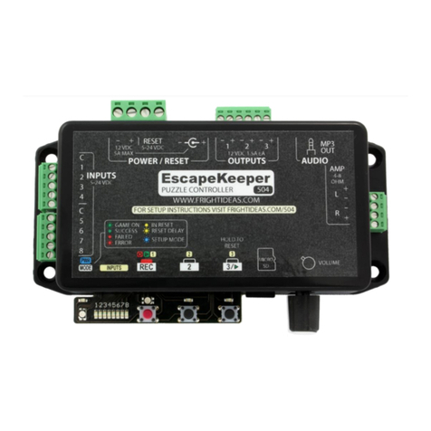
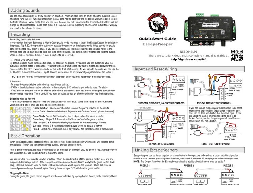
Fright Ideas EscapeKeeper User manual

Fright Ideas

Fright Ideas EscapeKeeper User manual

Fright Ideas BooBox Mini User manual

Fright Ideas

Fright Ideas BooBox Mini User manual

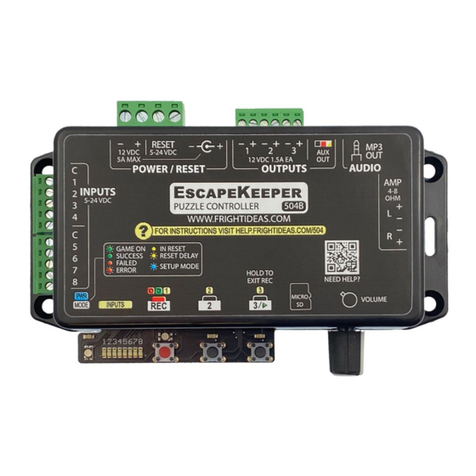
Fright Ideas EscapeKeeper User manual

Fright Ideas

Fright Ideas EscapeKeeper User manual

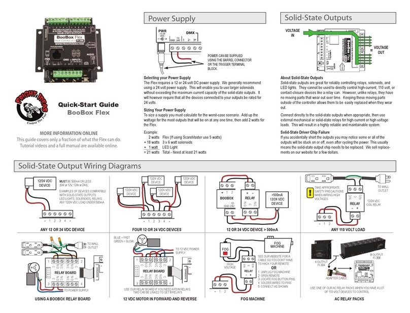
Fright Ideas BooBox Flex User manual

Fright Ideas

Fright Ideas BooBox Flex User manual

Fright Ideas EscapeKeeper JR User manual

Fright Ideas

Fright Ideas EscapeKeeper JR User manual

Fright Ideas BooBox FlexMax User manual

Fright Ideas

Fright Ideas BooBox FlexMax User manual

Fright Ideas BooBox Flex User manual

Fright Ideas

Fright Ideas BooBox Flex User manual

Popular Controllers manuals by other brands

Beckett GeniSys 7575 manual

Beckett

Beckett GeniSys 7575 manual

Chauvet CA-6 Quick overview

Chauvet

Chauvet CA-6 Quick overview

Concoa 806 7014 quick start guide

Concoa

Concoa 806 7014 quick start guide

TIS ADS-4CH-0-10V installation manual

TIS

TIS ADS-4CH-0-10V installation manual

hot-steam SP3-110 installation manual

hot-steam

hot-steam SP3-110 installation manual

Evco EV3 CHIL instruction sheet

Evco

Evco EV3 CHIL instruction sheet

Skov DOL 535 Technical manual

Skov

Skov DOL 535 Technical manual

Plasmatronics PL20 Reference manual

Plasmatronics

Plasmatronics PL20 Reference manual

Epever Tracer6210AN user manual

Epever

Epever Tracer6210AN user manual

Contemporary Research ICC2-VDC brochure

Contemporary Research

Contemporary Research ICC2-VDC brochure

AMI 186 Installation, operation and maintenance instructions

AMI

AMI 186 Installation, operation and maintenance instructions

P&B MPC2000D manual

P&B

P&B MPC2000D manual

Vitek VT-TKBD11 operating manual

Vitek

Vitek VT-TKBD11 operating manual

eletor Speed Control Series instruction manual

eletor

eletor Speed Control Series instruction manual

THORLABS ORIC PDXC2 user guide

THORLABS

THORLABS ORIC PDXC2 user guide

Ltech SE-12-100-500-W1D manual

Ltech

Ltech SE-12-100-500-W1D manual

Winmate I370EAC-201 user manual

Winmate

Winmate I370EAC-201 user manual

WAGO 750-806 manual

WAGO

WAGO 750-806 manual

manuals.online logo
manuals.online logoBrands
  • About & Mission
  • Contact us
  • Privacy Policy
  • Terms and Conditions

Copyright 2025 Manuals.Online. All Rights Reserved.