FRM Terrae User manual

RIDEIN STYLE
User’s manual

Dear customer
First of all we want to congratulate you for your new
purchase, we are convinced that the Terrae will give you
great satisfaction.
You have just acquired a unique product, with
state-of-the-art technological solutions and materials,
This is the user's manual where you will find all the neces-
sary instructions to carry out the basic maintenance of all
our components
If your Terrae is regularly serviced and used in the right
way, it will accompany you faithfully over time, maintain-
ing its performance unaltered.
RIDEIN STYLER IDEIN STYLE

Assembling the TERRAE is no witchcraft,
but you should proceed with care and
deliberation. Unprofessional assembly
can render the bike unsafe.
First we should like to make you familiar
with the various components of your FRM
First, open the box
To do this, only use a box cutter or a
similar knife with a very short blade.
Never use any kind of knife on the bicycle
itself.
CHECKING THE CONTENTS OF BOX
The box contains the assembled frameset
with the rear wheel mounted and all
add-on parts as well as the front wheel,
the saddle with seat post, and the FRM
assembly paste.
When using a box cutter make sure
you do not damage the component or
injure yourself.
Make it a rule to cut away from yourself
and the component!
Share the pleasure that your new
FRM brings and ask a helper to assist
you in unpacking it from the box and in
assembling it.
The easiest and safest way to assem-
ble the bike is when you use a work-
stand or ask someone to help you.
Your FRM had been fully assembled at
the factory and given a test run. The
bicycle should be fully functional without
any further adjustments being made once
the assembly steps explained below have
been completed.
Before your first ride, carry out the checks
described in chapter “Before every ride”.
Do not clamp a frame tube or a car-
bon seat post of your FRM in the hold-
ing jaws of the workstand! Be sure to
only use a suitable aluminium seat post
for clamping. It is best to use a work-
stand that holds the frame from inside
at three points or else ask someone to
help while you assemble your bike.
Exceeding the maximum torque at the
clamping bolts (e.g. at the stem, steerer
tube, handlebars or seat post) leads to an
excessively high clamping force. This can
cause the component to fail and hence
there is a high associated risk of
accidents. In addition, the product guar-
antee would be null and void in such a
case. Screws or bolts that are too loose or
are done up too tightly can cause a failure
and hence lead to an accident. Always
follow exactly the tightening torque details
from FRM
RIDEIN STYLE
ASSEMBLY THE TERRAE GENERAL INFORMATION ON GRAVEL BIKE ASSEMBLY

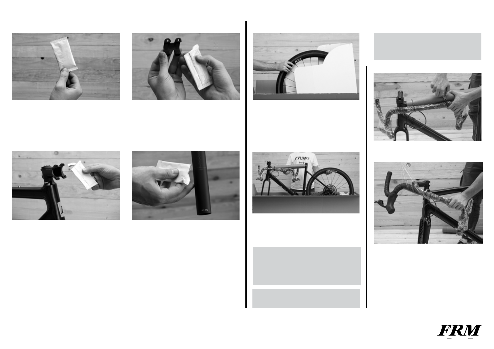
USING THE FRM ASSEMBLY PASTE
Carbon fibre components are particularly
vulnerable to damage caused by exces-
sive clamping force. FRM assembly paste
creates extra friction between two surfac-
es, allowing the necessary torque value to
be reduced by up to 30 %.
This is especially useful in the clamping
areas of handlebars and stem, steerer
tube and stem and seat post and stem,
i.e. three areas where too much clamping
force can damage either component,
causing component failure or voiding the
warranty. By reducing the clamping force,
FRM assembly paste relieves stress on
sensitive carbon surfaces, preventing
damage to fibres or the cracking of the
carbon substructure.
It also retains its effectiveness in wet con-
ditions and provides maximum protection
against corrosion. FRM assembly paste
can be used for all carbon and aluminium
connections. It’s ideal for this purpose, as
it does not harden.
Prior to applying FRM assembly paste,
remove dirt particles and lubricant
residues from the surfaces to be treated.
Apply a thin and even film of FRM assem-
bly paste to the cleaned surfaces using a
brush or a chamois. Mount the compo-
nents, as specified. Use a torque wrench
and never exceed the prescribed maxi-
mum tightening torque! Remove exces-
sive FRM assembly paste and reseal the
small sachet after use.
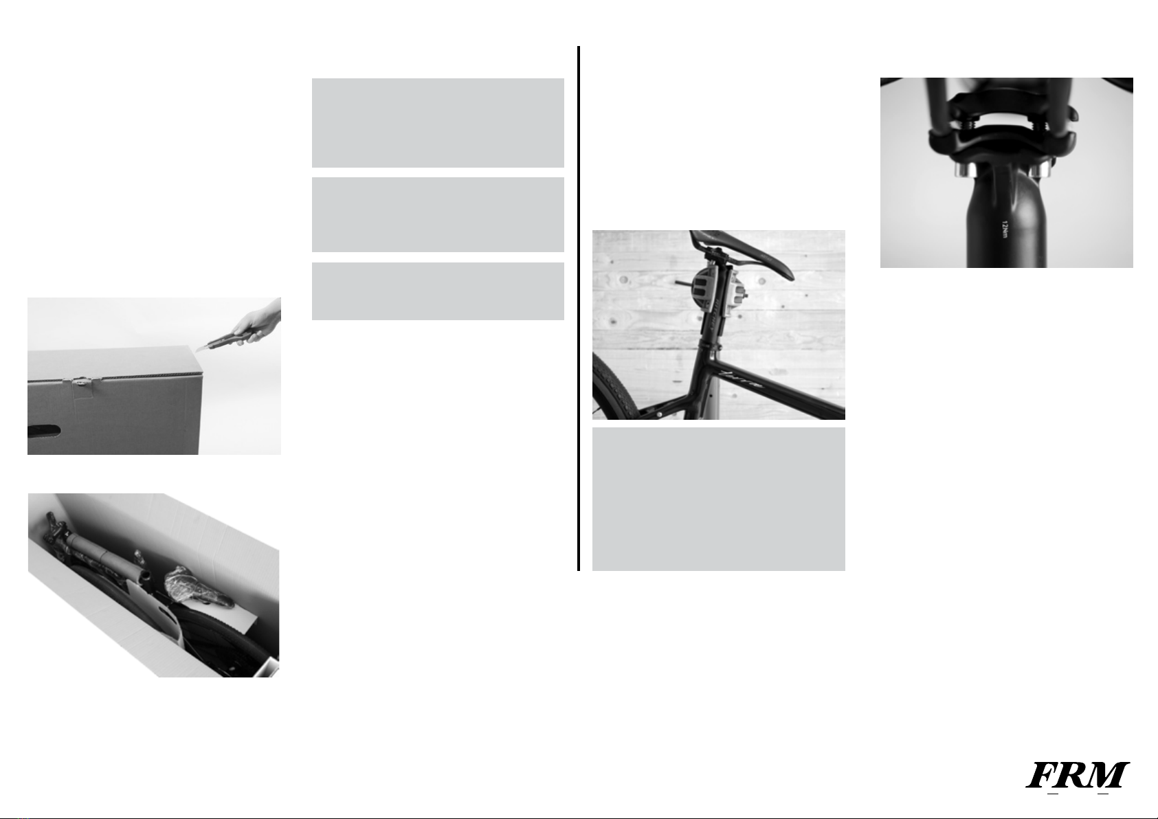
Remove the protective cardboard at one
end.
Take out the cardboard box with the front
wheel stowed in parallel to the bike frame
in the box.
Lift the frame including add-on parts and
rear wheel carefully off the bike box and
make sure it stands safe. Ask your helper,
if necessary, to hold the bike.
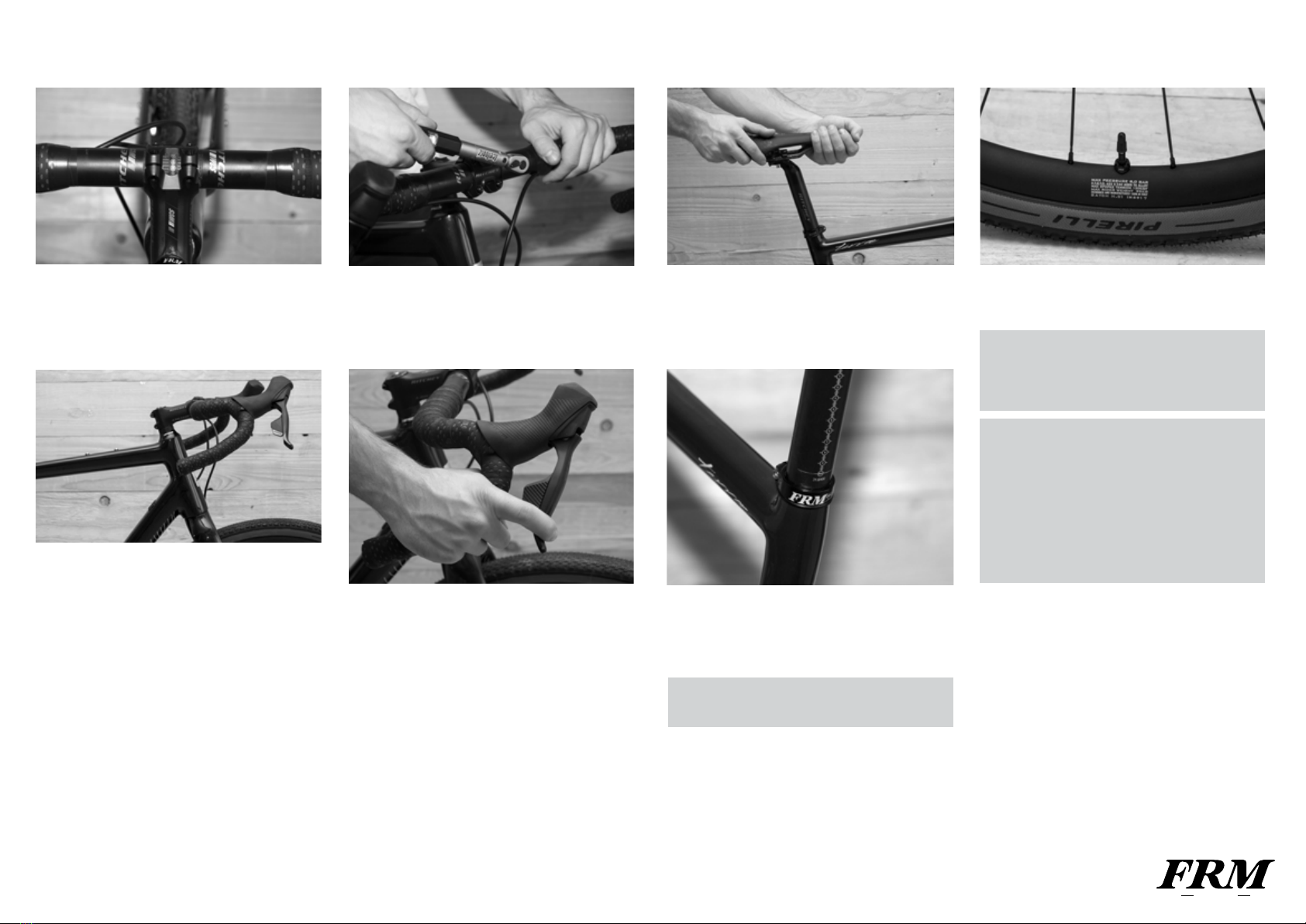
MOUNTING THE HANDLEBARS
Keep hold of the handlebars to prevent
any twisting, dropping and damage.
RIDEIN STYLE
Keep the entire packaging material
as well as the cardboard box in a dry
place. If you intend to ship your FRM
or to take it with you on a trip, you will
have everything at hand.
You will not find the wheels packed in
wheel bags in every bike box
Hold the handlebars tightly while lifting
the frame out so that they are not twist-
ed, cannot drop and get damaged.
Remove the protective film and sleeves
from the handlebars. It is recommended
that you remove the protective material in
general by hand. If that is not possible, it is
best to use scissors, and if it is really
necessary, use a box cutter.
Let the handlebars carefully hang down.
UNPACKING

Put the matching bit into the holder of the
torque wrench. Release the clamping
bolts of the stem faceplate and remove
the faceplate.
Open the FRM assembly paste. Squeeze
out some assembly paste and apply a thin
layer of carbon assembly paste on the
inner side of the faceplate as well as in the
clamp- ing area of the stem body.
Position the handlebars by means of the
marking accurately centred in the stem
clamp. Make sure the bowden cables and
the lines are not twisted or bent, but run in
a smooth curve to the cable stops or
brakes.
Retighten the clamping bolts of the face-
plate evenly in a cross pattern until they
lightly hold the handlebars in place.
MOUNTING THE FRONT WHEEL
MOUNTING THE SADDLE AND
THE SEATPOST
Remove the front wheel from the protec-
tive cardboard.
1
Remove the front wheel axle already
mounted on the fork.
Remove the plastic spacer from the
caliper, being careful not to operate the
brake lever.
After the wheel mounting, do a brake
test when stationary. Actuating the
brake lever should generate a clear-cut
braking response before the lever
touches the handlebars.
Apply a little FRM assembly paste on the
bottom part of the seat post and inside the
seat tube.
When using a box cutter make sure
you do not damage the component or
injure yourself. Make it a rule to cut
away from yourself and the component!
Do not pull the (disc) brake lever with a
removed wheel and make sure to
mount the safety locks when re-
moving the wheel.
You should be able to insert the seat post
easily into the frame without pressing or
turning. If you are not, loosen the seat
post binder bolt a little more.
Pull the seat post out again. Apply a little
FRM assembly paste to the bottom part of
the seat post and inside the seat tube or in
the clamping area of the seat post.
RIDEIN STYLE
1 4
32
Tightening sequence
MAX. 5Nm
2
Mount the front wheel and make sure the
disc is centered between the pads.
Insert the axle from the right and tighten it
according to the recommended torque.

MOUNTING THE SADDLE AND
THE SEATPOST
Bring the saddle into alignment and do not
overtighten the seat post binder bolt, i.e.
do not exceed the permissible maximum
torque. Use the torque wrench.
Measure the saddle height of your
previous bicycle from the middle of the
bottom bracket up to the top edge of the
saddle in the middle of the saddle. Then
transfer the saddle height to your new
FRM
Remove the protective film from the
saddle, if available.
Tighten up the Torx T25 bolt of the seat
post clamp to the prescribed torque of 4
Nm up to a maximum of 6 Nm.
Your seat post must go into the frame as a
minimum to as far as underneath the top
tube and up to the MAX marking of the
seat post.
MOUNTING THE PEDALS
FRM gravel bikes can be fitted with stan-
dard pedals of the major brands.
Please don’t forget to fully recharge the
battery of the rear derailluer with the dedi-
cated charger.
When done, insert it in the apposite slot
located where the plastic red cover is
placed.
Before mounting the pedals, check the
marking on the pedal axles first. “R”
stands for right pedal and “L” for left
pedal. Note that the left pedal has a
left-handed thread that has to be tight-
ened contrary to the direction you are
accustomed to, i.e. anticlockwise.
Apply a thin layer of standard assembly
grease on the pedal threads before
screwing in the pedals.
Screw each pedal manually into the
thread of its crank by two to three full
turns. Continue by using a pedal spanner
to tighten the pedals firmly. Some pedal
types have to be tightened with an Allen
key.
RIDEIN STYLE
Slide the seat post into the seat tube to
the desired saddle height.
Never ride your FRM if the MAX mark-
ing of the seat post is visible.
Never apply any grease or oil to clamp-
ing areas made of carbon!
Do not exceed the maximum tightening
torques! You will find the prescribed
values in chapter “Recommended
tightening torques”, directly on the
components and/or in the manuals of
the component manufacturers
Check the reliable fit of the pedals after
about 100 km (60 miles). The pedals
can come loose, and this can de- stroy
the thread and throw the rider off his
bike.
REAR DERAILLEUR BATTERY INSERT

CHECKING AND ADJUSTING
Make sure the upper and lower clamping
slots between faceplate and stem body
are parallel and identical in width. Release
the clamp- ing bolts, if necessary, and
re-tighten them slightly and evenly.
Verify that the upper grip areas of the shift/
brake levers are in horizontal position.
The ends of the drops are then in parallel
to the ground or point slightly downwards.
Use a torque wrench and finish by tighten-
ing the clamping bolts in cross pattern.
Do not exceed the maximum tightening
torques!
Check the proper functioning of the gears.
Shift through all gears and make sure the
rear derailleur does not collide with the
spokes when the chain runs on the largest
sprocket.
Adjust the position of the saddle and
handle- bars and check that the handle-
bars, grips and seat post are securely
fastened.
Your seat post must go into the frame as
a minimum to as far as underneath the
top tube and up to the MAX marking of the
seat post.
Inflate both tyres to the maximum pres-
sure indicated on the side of the tyres.
RIDEIN STYLE
Never ride your FRM if the MAX mark-
ing of the seat post is visible.
Check the reliable fit of all bolts
once again according to the prescribed
tightening torques after 100 to 300 km
(60 to 180 miles)
After completing the assembly and
checks it is essential to give your FRM
a test ride in a level, unfrequented area
(e.g. in a parking lot)! Wrong assembly
or improper adjustments that become
apparent in road traffic or during use of
your bike can make you lose control of
your FRM!

RIDEIN STYLE
TERRAE / SUGGESTED SERVICE INTERVALS
Rear derailleur
Freewheel
Saddle clamps
Seat tube clamp
Wheel axle
Stem
Brake / shifter lever
Mounting bolt
Cassette lock ring
Saddle clamps screw
Front / Rear
Screws
Clamp
Screw TorquePart
Tires
Tires
Disc brakes
Brake hose
Fork
Bottom bracket
Bottom bracket axle
Chain
Chain
Crankset
Wheels / Spokes
Handlebar and stem
Headset
Headset
Hubs
Hubs
Rear derailleur
Screws
check air pressure
check the tire condition
measure the thickness of the pads
visual inspection
check the screws
check bearings play
grease
check and, if necessary, lubricate
check and, if necessary, replace
check and tighten
Check alignment and tension
Check
check bearings play
grease
check bearings play
grease
clean and lubricate
check and, in necessary tighten
To do Before every ride Monthly Annual Various intervals
If you have good manual skills, experience and the right tools (e.g.
torque wrench), you can carry out the checks yourself.
Take immediate action if you detect problems during the checks.
The time intervals listed in the following table are references for cyclists
who ride 750 to 1,500 km per year (approx. 50 to 100 hours of use). The
inspection intervals are reduced in case of regular use of the bicycle on
roads in poor condition.
Part
every
1500/2000km
TORQUE CHART
replace after a fall
4-5 NmCable
8-10 Nm
30-40 Nm
5 Nm
5 Nm
10 Nm
5 Nm
Max 4 Nm

RIDEIN STYLE
Please refer to the manufacturer manual in order to get all the informations about
how to set up and register the components mounted on the Terrae.
TERRAE / C O M P ONENTS
www.servicearchive.sram.com/service
FRAME
FRM Terrae Carbon T 800, 3K
FORK
FRM T 800, 3K
STEM
Ritchey WCS Toyon
HANDLEBAR
Ritchey Beacon WCS
SEATPOST
Ritchey Comp Carbon 2-bolts; 31,6mm
SEATCLAMP
FRM SC32
SHIFTERS
RIVAL AXS
CRANKSET
RIVAL D1 172,5 mm 42 DUB Glossy Black
REAR DERAILLEUR
GX Eagle Lunar AXS
CASSETTE
SRAM X-Glide 1295 Black 12S 10-52
CHAIN
PC GX Eagle, 12 velocità con Power Lock
BB
DUB Press Fit ROAD WIDE
BRAKES
Sram Rival AXS
ROTORS
160mm centerlock
HEADSET
FSA
WHEELS
FRM Sterrato 24mm
SADDLE
Repente ARTAX GL
TIRES
PIRELLI CINTURATO
www.eu.ritcheylogic.com/eu_en/support/tech-info
Table of contents
Other FRM Bicycle manuals
Popular Bicycle manuals by other brands

Burromax
Burromax TT100R owner's manual

ARGON18
ARGON18 GALLIUM DISC 339A 2021 Assembly guide

Bulls
Bulls Sonic Evo AM-SL 1 Carbon Translation of original operating instructions

I-GO
I-GO Elite III hd user manual

Btwin
Btwin ELOPS 920E user manual

Bulls
Bulls Sonic EVO AM 2 Carbon Translation of original operating instructions