Frontier LS2011 User manual

LIQUID SPRAYER
OPERATOR'S MANUAL
LS2011
LS2015
5CS201115OM (rev 00 07/2020)
LS2011

5CS201115OM (rev 00 07/2020)2
TO THE DEALER:
Assembly and proper installation of this product is the responsibility of the Frontier dealer. Read manual instructions
and safety rules. Make sure all items on the Dealer’s Pre-Delivery and Delivery Check Lists in the Operator’s Manual
are completed before releasing equipment to the owner.
TO THE OWNER:
Read this manual before operating your Frontier equipment. The information presented will prepare you to do a better
and safer job. Keep this manual handy for ready reference. Require all operators to read this manual carefully and
become acquainted with all the adjustment and operating procedures before attempting to operate. Replacement
manuals can be obtained from your selling dealer.
The equipment you have purchased has been carefully engineered and manufactured to provide dependable and
satisfactory use. Like all mechanical products, it will require cleaning and upkeep. Lubricate the unit as specied.
Observe all safety information in this manual and safety decals on the equipment.
For service, your authorized Frontier dealer has trained mechanics, genuine Frontier service parts, and the necessary
tools and equipment to handle all your needs.
Use only genuine Frontier service parts. Substitute parts will void the warranty and may not meet standards required
for safe and satisfactory operation. Record the model number and serial number of your equipment in the spaces
provided:
Model: ___________________________ Date of Purchase: _____________________
Serial Number: (see Safety Decal section for location) ________________________________
Provide this information to your dealer to obtain correct repair parts.
Throughout this manual, the term NOTICE is used to indicate that failure to observe can cause damage to equipment.
The terms CAUTION, WARNING and DANGER are used in conjunction with the Safety-Alert Symbol, (a triangle with
an exclamation mark), to indicate the degree of hazard for items of personal safety.
This is the safety alert symbol. It is used to alert you to potential
physical injury hazards. Obey all safety messages that follow thus
symbol to avoid possible injury or death.
Indicates a hazardous situation that, if not avoided, will result in
death or serious injury.
Indicates a hazardous situation that, if not avoided, could result in
death or serious injury.
Indicates a hazardous situation that, if not avoided, could result in
minor or moderate injury.
Is used to address practices not related to physical injury.
Indicates helpful information.
DANGER
WARNING
CAUTION
IMPORTANT
or NOTICE
NOTE
Introduction

5CS201115OM (rev 00 07/2020) 3
This Operator's Manual should be regarded as part of the
machine. Suppliers of both new and second-hand machines must
make sure that the manual is provided with the machine.
Table of Contents
TABLE OF CONTENTS
INTRODUCTION 4
SAFETY 5
Safety and Instructional Labels 9
ASSEMBLY 11
INSTALLATION 17
OPERATION 19
SERVICE 24
TROUBLESHOOTING 26
SPECIFICATIONS 27
Tractor Ballasting 31
Parts Diagrams 32
Bolt Torque Chart 64

5CS201115OM (rev 00 07/2020)4
READ THIS MANUAL carefully to learn how
to operate and service your machine correctly.
Failure to do so could result in personal injury
or equipment damage. This manual and safety
signs on your machine may also be available in
other languages. (See your Frontier dealer to
order.)
The illustrations and data used in this manual
were current at the time of printing but, due to
possible in-line production changes, your
machine may vary slightly in detail. We reserve
the right to redesign and change the machines
as may be necessary without notication.
THIS MANUAL SHOULD BE CONSIDERED a
permanent part of your machine and should
remain with the machine when you sell it.
MEASUREMENTS in this manual are given in
both metric and customary U.S. unit
equivalents. Use only correct replacement parts
and fasteners. Metric and inch fasteners may
require a specic metric or inch wrench.
RIGHT-HAND AND LEFT-HAND sides are
determined by facing in the direction of forward
travel.
WARRANTY is provided as part of Frontier’s
support program for customers who operate
and maintain their equipment as described in
this manual. The warranty is explained on the
warranty certicate or statement which you
should have received from your dealer.
This warranty provides you the assurance that
Frontier will back its products where defects
appear within the warranty period. In some
circumstances, Frontier also provides eld
improvements, often without charge to the
customer, even if the product is out of warranty.
Should the equipment be abused, or modied to
change its performance beyond the original
factory specications, the warranty will become
void and eld improvements may be denied.
Setting fuel delivery above specications
or otherwise overpowering machines will result
in such action.
If you are not the original owner of this
machine, it is in your interest to contact your
local Frontier dealer to inform them of this unit's
serial number. This will help Frontier notify you
of any issues or product improvements.
GENERAL INFORMATION
Introduction

5CS201115OM (rev 00 07/2020) 5
Read Safety in Machine Operator’s Manual
Read the general safety operating precautions
in your machine operator’s manual for
additional safety information.
Operate Safely
• Read the machine and attachment
operator’s manual carefully. Be thoroughly
familiar with the controls and the proper use
of the equipment. Know how to stop the
machine and disengage the controls quickly.
• Do not let children or an untrained person
operate machine.
• Make any necessary adjustments before
you operate. Never attempt to make any
adjustments while the engine is running,
unless if recommended in adjustment
procedure.
• Take all possible precautions when leaving
the machine unattended. Shut off the engine
before making any repairs, adjustments, or
inspections. Lower the attachment, lock the
parking brake, stop the engine, and remove
the key.
• Look behind machine before you back up.
Back up carefully.
• Do not let anyone, especially children,
ride on machine or attachment. Riders are
subject to injury such as being struck by
foreign objects and being thrown off. Riders
may also obstruct the operator’s view,
resulting in the machine being operated in
an unsafe manner.
• Use only attachments and accessories
approved by the manufacturer of this
product.
• If the machine vibrates abnormally, stop
the engine and check immediately for the
cause. Vibration is generally a warning of
trouble.
• Always refer to the Storage section of the
operator’s manual for important details if
storing this product for a long period of time.
• Keep people and pets out of the work area.
Stop machine if anyone enters the area.
• If you hit an object, stop the machine and
inspect it. Make repairs before you operate.
Keep machine properly maintained and in
good working order. Keep all shields and
guards in place.
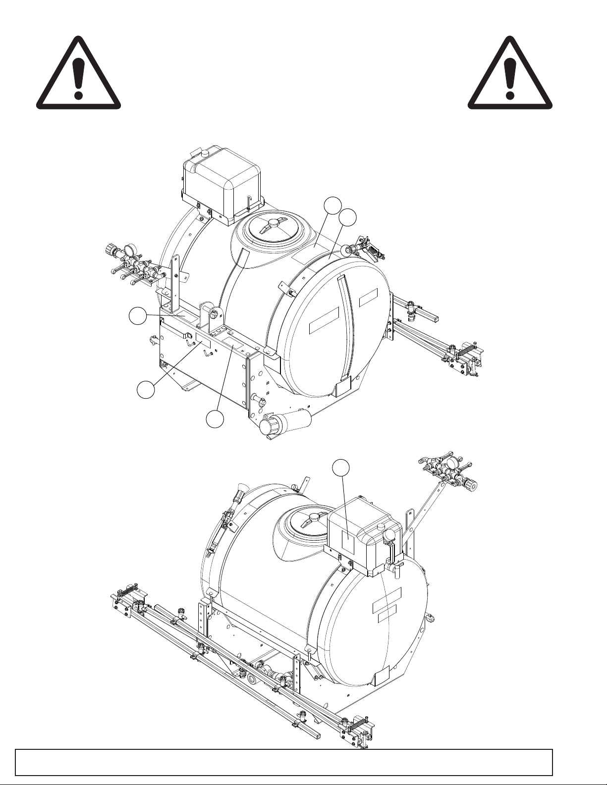
• Always inspect the sprayer completely
before and after each use. Before
pressurizing the system, check to be sure
all ttings and hoses are tightly installed.
Be sure guards and shields are in good
condition and fastened in place. Make any
necessary adjustments before you operate.
• Never use the sprayer during windy
conditions.
• Always release pressure in the system
before lling, cleaning or servicing the
sprayer.
• Do not put nozzle tip or other sprayer parts
to your lips to blow out dirt. Use compressed
air.
• Install the recommended light kit when this
equipment obscures the tractor’s tail lamps
or stop lamps when transported on the road.
Contact your Frontier dealer to obtain the
recommended light kit.
Parking Safely
1. Stop vehicle on a level surface, not on a
slope.
2. Lock park brake.
3. Lower 3pt attachment to the ground.
4. Stop engine.
5. Remove key.
6. Before you leave the operator’s seat, wait
for engine and all moving parts to stop.
Mix and Handle Chemicals Safely
• Wear full cover clothing and wear protective
goggles and rubber gloves to protect
yourself while handling chemicals
Safety
SAFETY

5CS201115OM (rev 00 07/2020)6
• Follow instructions on chemical container
labels.
• Open all chemical containers carefully, using
proper tools.
• Open, pour, weigh and mix chemicals in a
well-ventilated area.
• Reserve all equipment used for the
application of chemicals exclusively for that
purpose.
• Prohibit all smoking, drinking and eating
food in chemical-handling area.
• It is a good practice to take a soapy shower
immediately after the using the sprayer to
apply chemicals.
• Wash all clothing worn when using
chemicals separately in the laundry after
spraying is completed.
Read Chemical Container Label
• Chemicals can be dangerous. Improper
selection or use can injure persons, animals,
plants, soils or other property. Select the
right chemical for the job and handle and
apply with care.
• Read the instructions, precautions, and
warnings on the container label before
opening. Use the product strictly according
to label directions for specic applications, in
the amounts specied, at the times specied
and only when needed.
• Keep the container closed tightly except
when preparing the mix.
• Do not remove labels from chemical
containers. Store all chemicals in their
original containers.
• Do not mix chemicals unless stated on the
container label.
• Store chemicals when not in use according
to the container label.
Handle Chemical Products Safely
• Direct exposure to hazardous chemicals
can cause serious injury. Potentially
hazardous chemicals used with Frontier
equipment include pesticides, herbicides
and fungicides.
• A Safety Data Sheet (SDS) provides specic
details on chemical products: physical and
health hazards, safety procedures, and
emergency response techniques.
• The SDS should be obtained from the
chemical dealer at the time of the chemical
purchase.
• Check the SDS before beginning any job
using a hazardous chemical. Know exactly
what the risks are and how to do the job
safely.
• Always wear recommended personal
protection equipment.
Practice Safe Maintenance
• Only qualied, trained adults should service
this machine.
• Understand service procedure before doing
work. Keep area clean and dry.
• Do not operate the engine in a conned
space where dangerous carbon monoxide
fumes can collect.
• Never lubricate, service or adjust the
machine or attachment while it is moving.
Keep safety devices in place and in working
condition. Keep hardware tight.
• Keep hands, feet, clothing, jewelry, and long
hair away from any moving parts, to prevent
them from getting caught.
• Lower any attachment completely to
the ground or to an existing attachment
mechanical stop before servicing the
attachment. Disengage all power and stop
the engine. Lock park brake and remove the
key. Let machine cool.
• Disconnect battery before making any
repairs.
Safety

5CS201115OM (rev 00 07/2020) 7
• Before servicing machine or attachment,
carefully release pressure from any
components with stored energy, such as
hydraulic components and springs.
• Release hydraulic pressure by lowering
attachment or cutting units to the ground or
to a mechanical stop and move hydraulic
control levers.
• Securely support any machine or
attachment elements that must be raised
for service work. Use jack stands or lock
service latches to support components when
needed.
• Never run engine unless park brake is
locked.
• Keep all parts in good condition and properly
installed. Fix damage immediately. Replace
worn or broken parts. Replace all worn or
damaged safety and instruction decals.
• Check all hardware at frequent intervals to
be sure the equipment is in safe working
condition.
• Do not modify machine or safety devices.
Unauthorized modications to the machine
or attachment may impair its function and
safety.
Transportation
• Use additional caution and reduce speed
when under adverse surface conditions,
turning, or on inclines.
• Do not operate or transport on steep slopes.
• Do not operate or transport equipment while
under the inuence of alcohol or drugs.
• Always comply with all state and local
lighting and marking requirements.
• Install the recommended light kit when this
equipment obscures the tractor’s tail lamps
or stop lamps when transported on the road.
Contact your Frontier dealer to obtain the
recommended light kit.
Storage
• Block equipment securely for storage.
• Keep children and bystanders away from
storage area.
Wear Appropriate Clothing
• Wear close tting clothing and safety
equipment appropriate for the job.
• Certain operating conditions may dictate
that the operator and any passenger
wear appropriate safety equipment while
operating the vehicle. Be prepared for any
existing and potential conditions before
operating machine.
• Local safety or insurance regulations may
require additional safety equipment such as
eye protection or a hard hat.
• Always wear substantial footwear and long-
legged pants. Do not operate the equipment
when barefoot or wearing open sandals.
• Wear proper clothing and safety equipment
while handling chemicals or using the
sprayer. Refer to the SDS for the chemicals
being used to be sure the proper personal
protection equipment is being used.
Dispose of Chemicals Properly
• Proper disposal of excess spray material
is very important. If you have excess tank
solution, it is best to dilute it with water and
apply it to the area you previously treated.
• Never dump solution into a drain or near a
lake or stream.
• Chemicals containers should be triple-
rinsed, with the rinse water added to the
sprayer tank. Do not burn empty chemical
containers. Dispose of containers at
recycling centers.
Safety

5CS201115OM (rev 00 07/2020)8Safety
Handling Waste Product and Chemicals
Waste products, such as, used oil, fuel, coolant,
brake uid, and batteries, can harm the
environment and people:
• Do not use beverage containers for waste
uids someone may drink from them.
• See your local Recycling Center or
authorized dealer to learn how to recycle or
get rid of waste products.
• A Safety Data Sheet (SDS) provides specic
details on chemical products: physical and
health hazards, safety procedures, and
emergency response techniques. The seller
of the chemical products used with your
machine is responsible for providing the
SDS for that product.

5CS201115OM (rev 00 07/2020) 9
SAFETY AND INSTRUCTIONAL LABELS
ATTENTION! BECOME ALERT! YOUR SAFETY IS INVOLVED!
Replace Damaged or Missing Labels Immediately!
CAUTION
1. Read and understand the Operator’s Manual before using.
2. Tractor cab may not provide sufficient protection. See Tractor’s
Operator’s Manual.
3. Stay away from chemicals, spray, and drift.
4. Before servicing or filling sprayer, lower all equipment to the
ground, set the park brake, stop the engine, and remove the key.
5. Keep hands, feet, hair, and clothing away from moving parts.
6. Clear the area of bystanders before extending or folding booms.
7. Do not allow riders.
8. Keep others away.
ST50910
To avoid injury from chemical
hazards due to eye and skin contact,
inhalation, and ingestion, wear
personal protective equipment. Read
and follow chemical manufacturer’s
labels and instructions.
ST50927
WARNING
1 - PN 5CS50910
2 - PN 5CS50927
MADE IN USA
DEERE & COMPANY, MOLINE, ILLINOIS, USA
Serial Number
*XXXXXXXXXXXXXXXXX*
110 GALLON LIQUID SPRAYER MODEL# LS2011
4 - Serial Number Tag
CAUTION
WARNING
Water for rinse/wash
purposes only.
Do not drink from this
container.
Container may become
contaminated by
sprayer chemicals.
Fill with clean rinse
water only.
ST50909
6 - PN 5CS50909
3 - PN 5CS4894
NOTICE
SST48594
If used or transported on
roadway, contact your
dealer to obtain necessary
lighting kit.
5 - 5CS50930 (LS2011) / 5CS50931 (LS2015)
LS2011 110 GALLON LIQUID SPRAYER
Mfg Date: MM/DD/YYYY
Mass (Empty): 271 - 450 Lbs (123 - 204 Kg)
Mass (Laden): 1229 - 1450 Lbs (557 - 658 Kg)
Tank Volume: 110 Gal (416 L)
Max Working Pressure: 150 psi (10.3 Bar)
Nominal Rotating Frequency: 540 RPM
ST50930
Safety

5CS201115OM (rev 00 07/2020)10
SAFETY AND INSTRUCTIONAL LABELS
ATTENTION! BECOME ALERT! YOUR SAFETY IS INVOLVED!
Replace Damaged or Missing Labels Immediately!
6
(Safety Decals continued from previous page)
4
5
2
3
1
Safety

5CS201115OM (rev 00 07/2020) 11Assembly
Dealer Set-Up Instructions
Assembly of this equipment is the responsibility
of the Frontier dealer. It should be delivered to
the owner completely assembled and adjusted
for normal operating conditions.
In most cases the sprayer will be shipped
completely assembled with the only
assembly being the boom, the fresh water tank
and 100 ft hose reel kit. The on-highway light
kit can be added to the sprayer at a later time if
desired.
Parts in Kit
Description Qty.
Sprayer Assembly 1
Boom 1
Hardware Kit 1
Fresh Water Tank 1
Hardware Kit
Description Qty.
Hose Clamp 1/2 in. 3
U-Bolt, 5/16 in. Square 3
Nut, 5/16 in. 6
Flange Bolt 5/16 in. x 3/4 in. (24 ft and 30 ft
Boom Only) 8
Remove Sprayer from Shipping Pallet
1. Remove plastic stretch wrap from sprayer
and boom.
2. Remove hardware that used to secure
sprayer to pallet and remove sprayer from
pallet.
3. If options are supplied, remove these from
the pallet.
4. Remove nut (A) to detach PTO pump from
sprayer and discard nut and bolt.
Install Fresh Water Tank
1. Install Spigot (A) onto Fresh Water Tank (B).
Spigot is located inside of tank for shipping.
2. Place Fresh Water Tank on Bracket (C) and
secure by routing Strap (D) over top of tank
to J-Hook (E).
A
ASSEMBLY

5CS201115OM (rev 00 07/2020)12
Control Valve Assembly
Control valve assembly is factory installed in a
vertical position to protect it during shipping.
This assembly should be re-positioned for
optimal use and accessibility following these
steps.
1. Carefully loosen bolts (A).
2. Rotate control valve to height required and
place bottom bolt in appropriate hole (B) for
desired position of valve. Tighten bolts.
Install Boom (18 ft and Boomless)
1. Center the boom on the rear of the main
sprayer.
2. Locate the (2) main upright support brackets
with holes.
3. Bolt the boom to the upright support
brackets using two 5/16 inch square U-bolts
(A) and four 5/16 inch ange nuts.
Install Boom (24 ft and 30 ft)
1. Center the boom on the rear of the main
sprayer.
2. Locate the (2) main upright support brackets
with holes.
3. Bolt the boom to the upright support
brackets using two 5/16 inch square U-bolts
(A) and four 5/16 inch ange nuts.
4. Fasten hinge brace to support brackets
using two 5/16 inch 3/4 inch ange bolts (B)
and two 5/16 inch ange nuts.
5. Secure side boom hinge to center boom
with hinge pin (A) and fasten with bowtie clip
(B).
B
B
A
A
B
Assembly
A
A
A

5CS201115OM (rev 00 07/2020) 13Assembly
6. Remove bolt (D) and retain.
7. Connect spring (C) to bolts on the hinge
backplate. Use of a spring puller will assist
with assembly.
8. Reinstall bolt (D) and adjust so that the
side boom is in line with center boom when
extended.
Boom Hose Connections
NOTE: The hoses are the length needed for
the 18 ft boom. For the 24 ft and 30 ft booms,
cut 8 inches off the hoses for the side booms
(A and C). For the boomless sprayers, pull the
hoses out to the side ttings and cut as needed,
leaving a little slack for adjustment of the
control valve assembly.
1. Connect the hoses from the control valve to
the appropriate sections of the boom.
2. Fasten with 1/2 inch hose clamps.
Boom Hoses
1. 18 ft boom: Use the wire ties (A) to fasten
the hoses to the top of the square tubing
of the side booms approximately 12 inches
away from both sides of the hinge pivot
center point. Leave slack in the hose
around the hinge area. Be sure the boom
folds without pinching the hose.
2. 24 ft and 30 ft booms: Use wire ties (A) to
fasten the hoses to the at support piece
connecting the side hinges of the side
booms, leaving the slack in the hose around
the hinge area. Be sure the boom folds
without pinching the hose.
Boom Adjustment
NOTE: 24 ft and 30 ft booms only.
1. Move the cross brace (A) to the appropriate
upper position (B) so that when the boom is
folded, the rubber bumper (C) stops against
the cross brace (A). If the top bolt holding
the boom is using the top hole among lower
positions (D) the top cross brace will also
use the top hole (B).
2. Put the S-Hook (E) through the eyebolt (F)
and mark the farthest spot down on the rope
where the S-Hook reaches.
3. Fold the boom.
4. Grab the rope with a hand about an inch or
two on either side of the marked spot on the
rope and push together to open the weave
in the rope. Put the opposite end of the
S-Hook through the rope.
5. Open boom.
6. Adjust the side boom until it is parallel with
the ground either by folding the boom and
A
B
D
C
ABC
A

5CS201115OM (rev 00 07/2020)14
attaching the S-Hook out farther on the
rope, or adjusting the eyebolt.
(Optional) Install 100 ft Hose Reel Kit
1. Install Hose Reel (A) on top of Mounting
Bracket (B) with the knob facing the front of
the sprayer using four 5/16" x 1/4" Carriage
Bolts (C) and four 5/16" Flange Nuts (D) as
shown.
2. Torque all fasteners to recommended
torque. (See Torque Table section)
3. Attach free end of 1/2" hose from Hose Reel
to Tee Fitting (E) and secure with 1/2" Screw
Type Hose Clamp (F).
(Optional) On-Highway Kit Installation
1. Install Right Hand Light Bracket (A) to
outside of uprights using two 5/16" x
3/4" Carriage Bolts (B) and two 5/16"
Flange Nuts (C). Torque Flange Nuts to
recommended torque. (See Torque Table
section)
2. Repeat Step 1 for Left Hand Light Bracket.
3. Install Rear Light Assembly (D) on Left Hand
and Right Hand Light Brackets ensuring that
both the red and amber lights are facing
the rear of the sprayer with the amber lights
on top, using four 1/4" x 1-1/4" Hex Bolts
(E) and four 1/4" Nylock Nuts (F) per light.
Nylock nuts should NOT be overtightened
as this could crack the plastic light housings.
Assembly
B
C
A
E
F
D
A
B
C
D
C
B
F
A
E
D

5CS201115OM (rev 00 07/2020) 15
4. Loosen Hose Guide Bracket (G) and route
Light Kit harness starting with two 4 pin
connectors alongside hoses.
5. Continue to route harness under the right
side of the sprayer on the inside of the
frame and above the brace that holds the
drain lter/valve assembly (H).
6. Route harness section labeled "LEFT" along
rear top frame section of sprayer.
7. Connect harness end connectors to right
and left lights.
8. Install push in cable clamp with wire ties.
Five on the inside of the frame section and
Three on the top of the back horizontal
frame section.
9. Remove slack in harness by pulling harness
to the front of the sprayer. Tighten wire
ties and re-tighten hose guide bracket.
Torque hose guide bracket ange nuts to
recommended torque. (See Torque Table
section)
10.Install SMV bracket (J) on the xed center
boom section, slightly left of center, by
slipping the bracket between the Hose (K)
and Square Tube (L) and secure using 5/16"
x 1-3/4" Square U-Bolt (M) and two 5/16"
Flange Nuts (N). Torque Flange Nuts to
recommended torque. (See Torque Table
section)
11. Connect 7 pin connector to the tractor's
trailer plug and test operation of Tail, Stop,
and Turn Signal Lights.
12.Disconnect 7 pin connector from tractor and
hang connector on Spare Hook (S) located
on front of sprayer.
Assembly
Q
PJ
R
N
K
L
M

5CS201115OM (rev 00 07/2020)16
(Optional) Install CAT 2 Pins
1. Starting on left side, remove CAT 1 Pin (A)
by removing 7/8” Nut and Lock Washer on
backside of frame. Retain hardware and
Linch Pin for installing CAT 2 Pin.
2. Remove four 1/2" x 1" Carriage Bolts (B).
3. Loosely Install the CAT 2 Side Bracket (C)
with the hole for the CAT 2 Pin closer to the
front of the sprayer using four 1/2" x 1-1/2"
Carriage Bolts (D) and 1/2" Flange Nuts (E).
4. Loosely Install CAT 2 Brace (F) under the
CAT 2 Side Bracket using two 1/2" x 1"
Carriage Bolts (G) and 1/2" Flange Nuts (E).
5. Install CAT 2 Side Pin (H) by inserting
pin into the holes in both the CAT 2 Side
Bracket and CAT 2 Brace using the Lock
Washer (J) and 7/8" Nut (K) from step 1.
Install Linch Pin from Step 1.
6. Torque hardware in the following order. (See
Torque Table section)
a. CAT 2 Side Pin Nut (K)
b. CAT 2 Side Bracket Flange Nuts (E).
c. CAT 2 Brace Flange Nuts (E).
7. Repeat Steps 1-6 for right side.
8. Replace CAT 1 Top Link Pin (L) with CAT 2
Top Link Pin (M) placing the CAT 2 Top Link
Pin in the upper holes (N) of the Top Link
Bracket and secure with Linch Pin from CAT
1 Top Link Pin.
B
A
B
G
F
J
K
C
D
E
H
M
N
L
Assembly
S

5CS201115OM (rev 00 07/2020) 17
Sprayer Installation
Installing Ballast
CAUTION: Avoid Injury! Machine can
become unstable when operating with
an attachment. Ballast is required when
the attachment is installed
• Do not use PTO adapters
Compact Utility Tractors
See Specication Section for implement code
and refer to Ballasting Machine in your tractor
operator’s manual to determine the number of
front weights required to ballast the tractor.
Mounting the Pump
1. Connect pump to tractor PTO shaft.
2. Brace torque arm against solid member of
tractor frame in the direction of PTO rotation.
DO NOT brace against the 3-point lift arms
or any other moving parts.
3. Connect chain fairly tight to tractor frame in
opposite direction.
Note: We recommend using the drawbar (if
possible) and wrapping the chain as shown
below.
Attaching the Sprayer to Tractor
1. Park machine safely. (See Park Machine
Safely in Safety section)
2. Lower tractor lift link to lowest position.
3. Mount sprayer on 3-point hitch.
Attaching the Sprayer to Tractor with
iMatch - Quick Hitch
1. Connect iMatch – Quick Hitch to tractor
rst following the iMatch – Quick Hitch
installation instructions.
2. Install bushing set (sold separately), John
Deere Part Number BW15056 or equivalent,
to lower draft pins and top link pin on
sprayer.
3. Lower the tractor’s 3-pt hitch aligning the
center hook of the iMatch – Quick Hitch just
below the top link pin on the sprayer.
4. Ensure all three connection points are
aligned.
5. Raise tractor’s 3-pt hitch ensuring lower
draft pins and top link are fully engaged with
iMatch – Quick Hitch.
6. Close both levers on iMatch – Quick Hitch
to lock lower draft pins in place. Levers
are closed when they are folded down
(horizontal position).
INSTALLATION
Installation

5CS201115OM (rev 00 07/2020)18
Removing and Storing Sprayer
Removing Sprayer from Tractor
CAUTION: Avoid Injury! When the
attachment is removed, also remove
any ballast that was added to the
machine.
1. Park machine safely. (See Park Machine
Safely in Safety section)
2. Lower sprayer to the ground.
3. Empty the sprayer tank. (See Operation
section)
4. Disconnect sprayer from 3-point hitch.
5. Disconnect pump from PTO shaft.
6. Store pump by hanging on hook by the
chain so that the pump and hoses do not
contact the ground.
Store Sprayer Safely
CAUTION: Avoid Chemical Injury
• Wear protective clothes, gloves
and goggles when handling
sprayer.
• Do not store sprayer with chemicals in tank.
• If sprayer comes in contact with your body,
immediately follow directions on chemical
container pertaining to spray material.
1. Open 3-way valve and drain excess uid
into chemical disposal container. (See
Dispose of Waste Properly in Safety section)
2. Rinse tank, pump, spray wand and all hoses
thoroughly with fresh clean water.
3. Repeat step 2 several times.
4. Allow tank to air dry.
5. Drain hoses and pump lter.
6. Check sprayer for worn or damaged parts.
Replace parts as needed.
7. Tighten loose hardware.
8. Store sprayer in a place where it will not
freeze.
9. Store pump by hanging on hook by the
chain so that the pump and hoses do not
contact the ground.
Installation

5CS201115OM (rev 00 07/2020) 19
Sprayer Setup
Filling Sprayer Tank
CAUTION: Chemicals can be
dangerous. Avoid injury to operator
or bystanders.
• Read chemical container label for mixing
and handling instructions. A Safety Data
Sheet (SDS) should be supplied by the
chemical dealer and provides proper safety
information.
• Wear proper clothing and safety equipment
while handling or applying spray chemicals.
• Wear a full covering of clothing, protective
goggles and rubber gloves.
• Prohibit all smoking, drinking, and eating
around chemicals.
• When lling tank, never allow end of water
hose to contact chemical mixture.
IMPORTANT: Avoid damage! Clean any spills
immediately with clean water prior to operating
sprayer.
1. Park machine safely. (See Park Machine
Safely in Safety section)
2. Lower tractor lift link so that the sprayer is
rmly on the ground.
3. Clean area around tank ller cap to prevent
tank contamination.
4. Remove tank ller cap and ll tank.
5. Install tank ller cap.
NOTE: The preferred location to ll the tank is
from the front left corner.
Draining and Cleaning the Sprayer Tank
IMPORTANT: Avoid damage!
• Clean any spills. Proper disposal
of excess spray is very important.
Dilute it with water and apply it to area
previously treated.
• Never dump excess into a storm drain or
near a lake or stream.
1. To quickly empty the tank of excess
material, turn 3-way valve (A) to drain
position as shown.
2. Spray all inside surfaces of tank with
low pressure garden hose to remove
any remaining solution. Rinse sprayer
tank, pump, sprayer wand and all hoses
thoroughly with fresh, clean water. Rinse
several times to make sure sprayer tank is
clean and free of chemicals.
3. When tank is empty, Allow tank to air dry.
4. Turn 3-way valve (A) to OFF position
(Vertical) and install ller cap.
OPERATION
Operation
LS2011
LS2015
A
A

5CS201115OM (rev 00 07/2020)20
Calibrating the Sprayer
When spraying with boom, sprayer must be
calibrated to ensure proper spray coverage and
to combat over-application or under-application.
The calibration process consists of three steps:
• Calculate speed of tractor.
• Determine nozzle size and consult
calibration chart for desired or instructed
gallon per acre (GPA).
• Set pressure using relief valve.
Calculating the Speed
It is important to determine what speed the
tractor will be traveling while spraying. Even if
tractor has a speedometer, it is still
recommended that speed be checked for
accuracy. Perform the following steps to
determine speed:
1. Measure a 200 or 300 foot distance on a
eld or surface similar to where sprayer will
be used.
2. Drive tractor with half-full sprayer across
measured distance at a constant and
3. comfortable speed for spraying. There can
be no changes in speed while measuring
time.
4. When using a gear-driven tractor, select a
gear where PTO is at or near 540 rpm. This
is important for pump to provide adequate
pressure to sprayer when spraying.
5. Determine amount of time, in seconds, it
takes to travel the measured distance.
6. Speed can be determined by entering data
into the following equation:
7. speed (mph) = (distance (ft) x 60) / (time
(sec) x 88) or by consulting the following
table:
NOTE: If using boomless nozzles, use the
Boomless Nozzle Calibration Chart.
Useful Formulas
GPA = Gallons per Acre
GPM = Gallons per Minute
MPH = Miles per Hour
GAL/1000 sq ft = Gallons per 1000 sq ft
W = Nozzle spacing in inches
GPM Per Nozzle = GPA x MPH x W / 5940
GPM Per Nozzle = GAL/1000 sq ft x MPH x W / 136
GPA = 5940 x GPM (Per Nozzle) / MPH x W
GPA = Gallons per 1000 sq ft / 0.023
GAL/1000 sq ft = 136 x GPM (Per Nozzle) / MPH x
W
Operation
Speed in
MPH
Time (sec) required to travel a distance
of:
200 ft 300 ft
1.0 136 205
1.5 91 136
2.0 68 102
2.5 55 82
3.0 45 68
3.5 39 56
4.0 34 51
4.5 30 45
5.0 27 41
5.5 25 37
6.0 23 34
6.5 21 31
7.0 19 29
This manual suits for next models
1
Table of contents
Other Frontier Paint Sprayer manuals