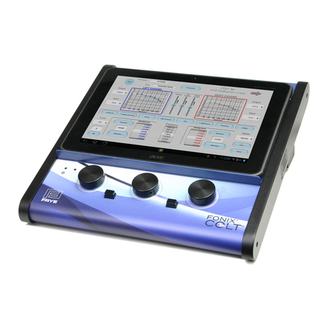
Frye FONIX COLT User manual

MAINTENANCE MANUAL
April 23, 2013
Copyright ©2013 Frye Electronics, Inc.
All Rights Reserved
FONIX® COLT™


Table of Contents
Chapter 1: Overview ............................................................1
1.0 Power on procedure for the Colt Audiometer ...........................................1
1.1 A Description of the Colt audiometer system ............................................3
1.2 The Tablet Operator Interface ...........................................................4
1.3 Microphone channels ...................................................................4
1.4 Digital Operation for Reliability .........................................................4
1.5 Control Simplicity ......................................................................4
1.6 Audio Power ............................................................................5
1.7 Blue Tooth Connectivity allows Operator Freedom ......................................5
1.8 Portability and Data Storage.............................................................6
1.9 RF Shielding.............................................................................6
Chapter 2: Specifications ........................................................7
2.1 General Characteristics..................................................................7
2.2 Pure Tone Signals .......................................................................7
2.3 Attenuators .............................................................................8
2.4 Signal Format............................................................................8
2.5 Channel Inputs..........................................................................8
2.6 VU Meters...............................................................................9
2.7 Channel Outputs ........................................................................9
2.8 Sound Field Speaker . . . . . . . . . . . . . . . . . . . . . . . . . . . . . . . . . . . . . . . . . . . . . . . . . . . . . . . . . . . . . . . . . . . . 9
2.9 Built in Speech Testing ..................................................................9
2.10 Regulatory .............................................................................9
Chapter 3: Specification Test Procedure.........................................11
3.1 Pure Tone Audiometric screen .........................................................11
3.1.1 Testing against a “normal” hearing threshold. ....................................11
3.1.2 A table of audiometric calibration values .........................................11
3.1.3 Reference to ANSI S3.6-2010 and IEC 60645-1 .....................................11
3.2 Speech Audiometric Screen ...........................................................11
3.2.1 Check of Speech Sound Levels ....................................................11
Chapter 4: Circuit Description.................................................. 13
4.1 Introduction............................................................................13
4.2 Block Diagram and Circuit Diagrams....................................................14
4.2.1 Circuit diagram sheets.............................................................14
4.3. CPU and associated circuits ...........................................................15
4.4. DSP Circuits............................................................................16
4.5. Analog input signals ...................................................................17
4.6. Speaker Power Output amplifiers......................................................18
4.7. Monitor Amplifier......................................................................18

4.8. Power Regulators......................................................................19
4.9. Power Supply..........................................................................19
Chapter 5: Calibration......................................................... 21
5.0 General ................................................................................21
5.1 Loading the ColtCal Program ...........................................................21
5.2 Running and Operation of the ColtCal Program ........................................21
5.2.1 Calibration Tables .................................................................21
5.2.2 Transducer Initial Data entry ......................................................23
5.2.3 Calibration Point by Point .........................................................23
Chapter 6: Service and Repair ................................................. 25
6.0 General Notes..........................................................................25
6.1 Fuse Replacement......................................................................25
6.1.1 Line Fuse Replacement ............................................................25
6.1.2 Main Board Fuse Replacement ....................................................26
6.2. Colt Circuit Assembly Removal and Separation ........................................27
6.3. Colt Circuit Reassembly ...............................................................27
Chapter 7: Maintenance ....................................................... 29
7.1 Power ..................................................................................29
7.2 Cleaning................................................................................29
7.3 Solvents ................................................................................29
Chapter 8: Safety Information ................................................. 31
8.0 Rear Panel Layout ......................................................................31
8.1 Rear Panel Safety Markings.............................................................31
8.2 Safety Classification for IEC 60601-1....................................................32
8.3 Connection of peripheral equipment to the Colt .......................................32
8.4 Disposal of the Colt and accessories....................................................32
Chapter 9: Electromagnetic Compatibility ...................................... 33
9.1 The Colt complies with IEC 60601-1-2. ..................................................33
9.2 Cables with which the Colt complies with IEC 60601-1-2 ...............................33
9.3 Accessories with which the Colt complies with IEC 60601-1-2 ..........................34
9.4 Guidance and manufacturer’s declaration – electromagnetic emissions ...............34
9.5 Recommended separation distances between portable and mobile RF communications
equipment and the Colt....................................................................37
Appendix A: Connectivity Chart................................................ 39

Chapter 1: 1
Chapter 1: Overview
1.0 Power on procedure for the Colt Audiometer
The basic Colt audiometer consists of two parts, the tablet and the main Colt base
unit. Both have to be powered and Blue Tooth wireless communication between the
two has to be established before operation. The procedure to follow:
Step 1- Turn on the power to the base colt unit
To turn on the power, plug the Colt line
cord into a suitable source of AC power
(100 to 250 VAC, 50 to 60 Hz) and switch
the power on by moving the rear panel
mounted toggle to the “-” position.
If a monitor headphone is plugged into
the rear panel monitor jack, a tone will
be heard in the monitor after power is
applied. This indicates that the Colt
hardware is operational and ready to be
linked to the tablet.
Step 2- Turn on the Colt tablet.
Press the power switch button
located on the side of the tablet
and hold it down for several
seconds.
A vibration may be felt and the
boot sequence will occur.

2 Maintenance Manual
When the booth sequence ends, a picture of a
lock will appear. Touch the lock and slide it to
the right.
The home screen
will then appear.
Step 3- Select the Colt icon from the home screen
Touch the
FRYE/Colt logo
icon on the
screen to
launch the Colt
application.

Chapter 1: 3
The pure tone Colt app screen will appear. A message will be seen on the screen,
indicating that blue tooth service is being actuated.
When the start-up sequence is complete, the tone from the monitor headset will
stop, indicating that communication and control has been established by the tablet.
Test the control by pressing the Stimulus button on either the right or left channel.
A tone will be heard in the monitor headset for the channel touched.
The Colt audiometer is now operational.
1.1 A Description of the Colt audiometer system
Audiometers are basically calibrated generators of pure tones which are used to
test people's hearing ability. The amplitudes of the tones used are adjusted to ap-
proximate that which people with “normal hearing” can hear. The Colt audiometer
also works in this way. It also allows the hearing professional to perform a variety of
tests, and is comparable in capability with the most complex of audiometers avail-
able today.

4 Maintenance Manual
1.2 The Tablet Operator Interface
But then, how is it different from any other audiometer? The differences and advan-
tages of the Colt lie in its operator interface. Instead of being computer based, it is
actually based on a multiple of computers. And one of these is devoted to handling
the operator interface. Through a tablet-based touch screen, it presents a virtual sys-
tem of keyboard devices to allow rapid and intuitive adjustment of controls, while
presenting an ongoing graph of the test results. The commands from the keyboard
are passed to the Colt Base unit, where digital electronics act on the commands to
produce the sounds and intensities called for.
1.3 Microphone channels
Multiple digital channels also amplify the microphone pickup of voices for talk
forward and talkback functions. A stereo monitor lets the operator know what sound
is being presented to the tested person. These are all standard audiometer functions
and are controlled with the tablet's virtual interface. But very few analog circuits are
involved in the generation, amplification and switching of the audiometer signals.
The complicated work is handled by the millions of digital transistors in multiple
integrated circuits under software control.
1.4 Digital Operation for Reliability
There are no screwdriver/pot adjustments in a Colt audiometer. Gain settings of
virtual amplifier stages are numbers embedded in a memory element, as are signal
generators and pulse and warble (FM) circuits.
Why go to all this trouble? A good reason for going digital is to eliminate a multitude
of moving parts. Adjustment controls like potentiometers wear out and/or become
unstable. The Colt’s calibration factors are stored in memory as numbers that are
stable and long-lived. Rarely does the instrument go out of calibration, because there
are no moving parts to deteriorate or fail, and no switch noise.
1.5 Control Simplicity
The Colt tablet interface works well in the audiometer environment, as it allows
the instrument to present only those controls that apply to the task at hand. In the
case of the pure tone test, the VU meter is not needed and so is not shown. Signal
choices are limited to those that are needed in pure tone testing. Speech noise is not
used. The talkback microphone is a precision calibrated unit that can now be used
to calibrate the sound field in an automatic sequence to allow adjustment to changes
in the acoustic environment.

Chapter 1: 5
In speech mode, the VU meter appears. The frequency dial disappears and is replaced
by a calculator which allows the user to score correct percentages automatically. Sets
of speech signals are selectable and can be played as desired. These are stored in a
miniature SD chip. The talk-forward microphone can now be used as a speech micro-
phone, with the gain set by a separate and adjustable front panel control to suit the
characteristics of the individual operator.
1.6 Audio Power
A high efficiency audio power amplifier is built into the system and allows relatively
high levels of sound intensity for sound field testing. It must be used, however, with
proper shielded cables that can carry both the drive and return signals on the tip and
ring of the ¼ inch plug/jack system. If the power of the Colt base is insufficient for the
intended purpose, an external amplifier can be used to drive the sound field.
Rear Panel
Socket Connector PIN 1
(Tip)
PIN 2
(Ring)
PIN 3
(Sleeve)
External Amp
Left & Right
PIN 1 PIN 2 PIN 3
3.5mm Stereo
Note: 3.5mm Mono
connector may be used.
SIGNAL N/A GROUND
Speaker
Left & Right PIN 1 PIN 2 PIN 3
1/4" Stereo (Required)
SPKR + SPKR – GROUND
Please note: The speaker output is from a class D amplifier. You cannot short out
the ring and sleeve of the stereo speaker connectors on the Colt audiometer. If you
purchase cables and speakers directly from Frye, the proper connections are made
for you.
1.7 Blue Tooth Connectivity allows Operator Freedom
Wireless Blue Tooth connectivity between the controlling tablet and the Colt base unit
allows the operator greater flexibility in the placement of audiometric components. No
longer is the audiologist tied to a fixed position close to the instrument with its key-
board or control panel.

6 Maintenance Manual
1.8 Portability and Data Storage
The instrument's small size and light weight makes it easily transported, so when
used in the field, a series of tests can be saved into the tablet's memory and later
downloaded to a computer at the office. Test data files are linked to the patient num-
ber. Privacy is thus maintained if something should happen to the Colt audiometer
and associated tablet. A NOAH interface is available through the FONIX audiometer
module using an external computer connected by a USB cable to the Colt base unit.
1.9 RF Shielding
Extensive shielding makes the Colt audiometer capable of meeting the toughest in-
ternational standards for RF emissions and susceptibility.
Other manuals for FONIX COLT
1
Table of contents
Other Frye Measuring Instrument manuals


