iii
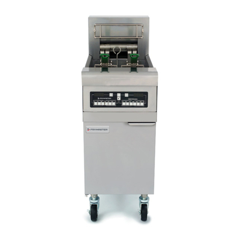
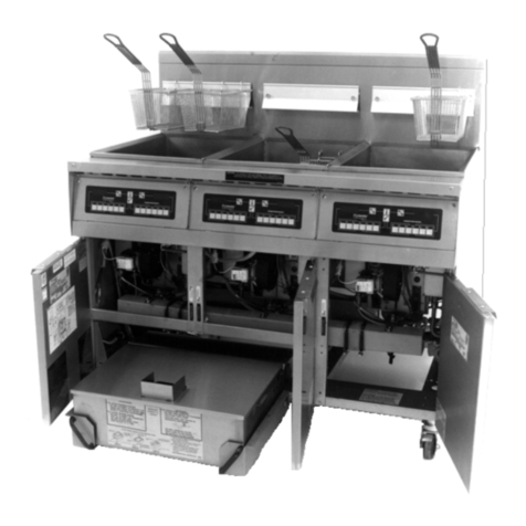
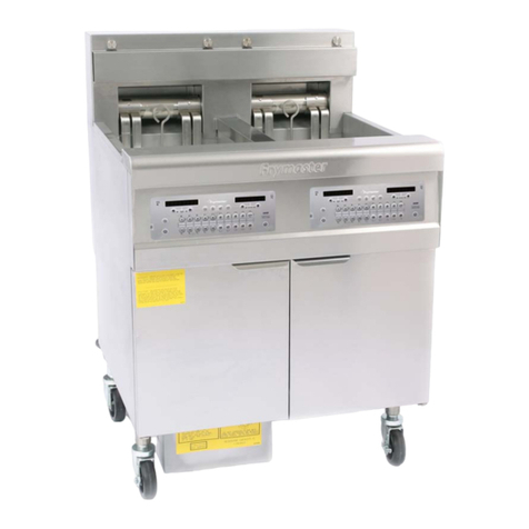
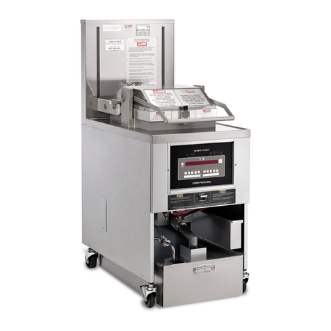
FRYMASTER 1814E SERIES ELECTRIC FRYERS
TABLE OF CONTENTS
CAUTIONARY STATEMENTS........................................................................................................ i
ELECTRICAL POWER SPECIFICATIONS................................................................................. ii
CHAPTER 1: Service Procedures
1.1 General ..............................................................................................................................1-1
1.2 Replacing a Controller.......................................................................................................1-1
1.3 Replacing Component Box Components..........................................................................1-1
1.4 Replacing a High-Limit Thermostat..................................................................................1-3
1.5 Replacing a Temperature Probe........................................................................................1-3
1.6 Replacing a Heating Element............................................................................................1-5
1.7 Replacing Contactor Box Components.............................................................................1-6
1.8 Replacing a Frypot ............................................................................................................1-7
1.9 Built-In Filtration System Service Procedures..................................................................1-9
1.9.1 Filtration System Problem Resolution ...............................................................1-9
1.9.2 Replacing the Filter Motor, Filter Pump and Related Components.................1-10
1.9.3 Replacing the Filter Transformer or Filter Relay.............................................1-11
1.10 Basket Lift Service Procedures .......................................................................................1-12
1.11 Interface Board Diagnostic Chart....................................................................................1-15
1.12 Probe Resistance Chart....................................................................................................1-16
1.13 Wiring Diagrams.............................................................................................................1-17
1.13.1 Basket Lift Wiring 208-250V...........................................................................1-17
1.13.2 Basket Lift Wiring 100-120V...........................................................................1-18
1.13.3 Standard 1814E Control Wiring.......................................................................1-19
1.13.4 BK1814E Control Wiring ................................................................................1-20
1.13.5 Component Box Wiring ...................................................................................1-21
1.13.6 Tilt Switch Wiring............................................................................................1-22
1.13.7 Contactor Wiring – 17kW Full Vat DELTA SSR 208-250V ..........................1-23
1.13.8 Contactor Wiring – 17kW Full Vat DELTA Mechanical 208-250V...............1-24
1.13.9 Contactor Wiring – 17kW Full Vat DELTA Mechanical 480V ......................1-25
1.13.10 Contactor Wiring – 17kW Dual Vat DELTA SSR 208-250V.........................1-26
1.13.11 Contactor Wiring – 17kW Dual Vat DELTA Mechanical 208-250V/480V....1-27
1.13.12 Contactor Wiring – 22kW Full Vat DELTA SSR 208-250V ..........................1-28
1.13.13 Contactor Wiring – 22kW Full Vat DELTA Mechanical 208-250V...............1-29
1.13.14 Contactor Wiring – 22kW Full Vat DELTA Mechanical 480V ......................1-30
1.13.15 Contactor Wiring – 17kW and 22kW Full Vat WYE SSR 208-250V.............1-31
1.13.16 Contactor Wiring – 17kW and 22kW Full Vat WYE Mech 208-250V/480V.1-32
1.13.17 Contactor Wiring – 17kW Dual Vat WYE SSR 208-250V.............................1-33
1.13.18 Contactor Wiring – 17kW Dual Vat WYE Mechanical 208-250V..................1-34
CHAPTER 2: Parts List
2.1 Accessories........................................................................................................................2-1
2.2 Basket Lift Assembly and Associated Parts......................................................................2-2
2.3 Doors, Sides, Tilt Housings, Top Caps and Casters..........................................................2-4
2.4 Drain System Components................................................................................................2-5
2.4.1 Drain Tube Sections and Associated Parts......................................................... 2-5
2.4.2 Drain Valves and Associated Parts (Units with Built-In Filtration) ..................2-7

