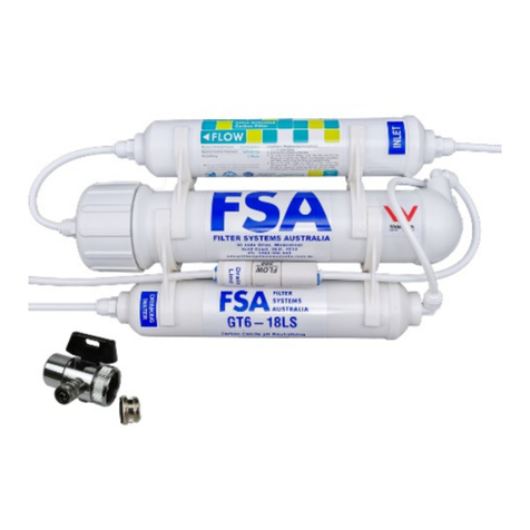
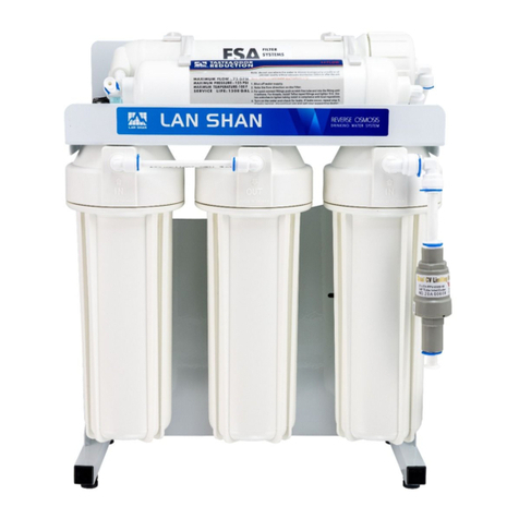
FSA GT1-26-5 User manual

Page | 1
GT1-26-5
5 Stage Undersink RO
Contents
Technical Overview......................................................................................................................................2
I. Important Notes .....................................................................................................................................2
II. Before You Purchase/Open ..................................................................................................................2
III. Space Requirements............................................................................................................................2
IV. Before You Begin Installation...............................................................................................................2
V. What is Reverse Osmosis.....................................................................................................................2
Installation Introduction.................................................................................................................................3
I. Working with Quick Connect Fittings......................................................................................................3
II. Flushing................................................................................................................................................3
Installing Connections ..................................................................................................................................3
I. Feed Water Connection.........................................................................................................................3
II. Drain Clamp..........................................................................................................................................3
III. Drilling Faucet Hole - Stainless Steel Sink) ..........................................................................................3
IV. Mounting the Faucet............................................................................................................................4
.................................................................................................................................................................4
V. Storage Tank Assembly........................................................................................................................4
VI. Assembling the System (Photos Below) ..............................................................................................5
Connecting the RO System ..........................................................................................................................6
I. Tubing....................................................................................................................................................6
System Start Up & Operation........................................................................................................................6
I. Plumber Commissioning Steps ..............................................................................................................6
II. Client can Complete Commissioning.....................................................................................................6
III. Automatic Shut Off...............................................................................................................................7
IV. Turning the System On/Off..................................................................................................................7
Maintenance.................................................................................................................................................7
I. Replacement Parts.................................................................................................................................7
II. Replacement Cartridges .......................................................................................................................7
III. Testing Filters ......................................................................................................................................7
Troubleshooting............................................................................................................................................8
Additional Extras.........................................................................................................................................11
I. Water Hammer Arrester.......................................................................................................................11
II. Leak Shut Off Kit.................................................................................................................................11

Page | 2
Technical Overview
I. Important Notes
For correct operation of this appliance, it is essential to observe the manufacturer’s instructions.
Installation must be carried out by a qualified plumber or authorised technician to comply with Australian
Plumbing Codes. This RO system is certified to WaterMark Standards AS/NZS 3497 Under the Certificate
number 23247. WaterMark certification is the level of certification required by law for a licensed plumber in
Australia to install a water filter system.
You will find most answers to your queries can be found in this instruction manual – please
thoroughly read through this manual from front to back including the troubleshooting page before
contacting customer support.
II. Before You Purchase/Open
The system requires specific working conditions to be met before installation. If these conditions are not
met, the system may not be suitable for the application and may not function as specified.
Feed Water
Conditions
Min
Max
Inlet Pressure
350 kPa
700 kPa
Temperature
4.5°C
38°C
pH Level
2
11
TDS
0 mg/L
2,000 mg/L
Iron
0 mg/L
0.3 mg/L
Manganese
0 mg/L
0.1 mg/L
Hardness
0 mg/L
200 mg/L
III. Space Requirements
System Dimensions (5 Stage)
Height: 43cm
Width: 37cm
Depth: 21cm
Storage Tank Dimensions (12L)
Height (With Stand): 42cm
Height (No Stand): 38.5cm
Width: 27cm
IV. Before You Begin Installation
All components that come pre-assembled will need to be thoroughly checked before installation. Due to
transit, fittings and other components may be loosened or unseated – ensure fittings, tubing and filters are
inspected before continuing.
V. What is Reverse Osmosis
Reverse osmosis is a process that uses a semi permeable, spiral wound membrane to separate and
remove dissolved solids, organics, pyrogens, colloids and bacteria from water. The Feed water is delivered
under pressure at 50psi or above through the permeator where the water permeates the minute pores of
the membrane and is split into purified water which is delivered to the tap, and concentrate (reject) water
which is sent to waste. Reverse Osmosis is capable of removing 85 – 99.99% of a large range of solids
from water (depending on the solid) along with Organics and Bacteria.

Page | 3
Installation Introduction
I. Working with Quick Connect Fittings
If you come across a push-fit fitting, you
need to firmly push the tubing into the
opening until you feel a “click” which
signifies that the tubing has pushed
through the internal O-ring and is seated
correctly. If leaking occurs, it may be due
to roughly cut tubing OR the tubing is not
pushed in far enough. To remove tubing
from push-fit fittings, depress the floating
collet (shown to the right), then pull the tubing out.
II. Flushing
Laws and regulations prevent us from wet-testing these filtration systems prior to sending them out.
Therefore, during assembly of these systems they are not pressure tested so it is possible to have a small
leak in a connection (which is simply fixed by re-seating the tubing or tightening a fitting). As the filters are
dry packed, the systems will require flushing before first use.
Installing Connections
I. Feed Water Connection
Using the supplied Feed Water Adaptor [FWA] (Pictured right), Locate the
connection between the kitchen tap & cold-water line (Usually a flex line). Shut
off the incoming water and bleed pressure from the line by opening the tap.
Disconnect the flex line from the cold-water inlet and install the Feed Water
Adaptor in between.
DO NOT apply thread tape to these connections as they are designed to use the
washers only – Thread tape is only required on the male thread of the FWA if it is
not installing to a flex line.
With the blue handle facing in line with the cold-water line (As pictured) the valve is
in the off position. During this point, you can turn the water back on to check for
leaks in the valve installation.
A pressure limiting valve must be fitted between the FWA and the Filter System to
limit the incoming pressure to a maximum of 500 kPa (70 PSI). Failure to install a
PLV may void warranty.
II. Drain Clamp
The best installation point for the drain clamp is below the S bend
(Trap). The Vertical tailpiece is ideal.
1. Mark the position of the hole on the pipe and drill through using
a ¼” (6mm) drill bit (One side only).
2. Unscrew the clamp and wrap it around the pipe, loosely screw
it back up leaving enough slack so you can position the hole
with the outlet of the clamp.
3. Tighten the clamp to create a seal.
III. Drilling Faucet Hole - Stainless Steel Sink)
1. Drilling through a stainless-steel sink can be achieved by marking the location with a centre punch
and drilling a 3/16” Pilot Hole – When drilling through stainless steel – lower speeds are better with
a sharper bit to avoid burning the surface of the sink.
2. Using a 1/2” or 7/16” carbide or sharp drill bit, enlarge the hole to fit the stem of the faucet (7/16”
Thread)

Page | 4
For installation on other types of sinks – such as stone, it is best to employ a specialist to drill the hole to
ensure it is done correctly – where possible it is best to get the sink manufactured with a pre-drilled hole.
IV. Mounting the Faucet
1. Refer to the below diagram on the components of the faucet
2. Remove the required fixings of the faucet and thread the faucet through the hole.
3. Re-assemble the faucet fixings in the correct order and tighten into place.
4. The Faucet uses a compression fitting to connect to the filtered water tubing. Compression fittings
crimp the tubing around a stem (gasket) to seal the water, the compression ring then prevents the
tubing from being removed. In this instance, thread the Compression nut over the tubing, followed
by the cone washer. Then firmly press the gasket into the end of the tubing. You can then insert the
tubing into the base of the faucet and secure it by fastening the compression nut onto the bottom of
the faucet thread.
V. Storage Tank Assembly
1. Using standard white plumbers’ tape – wrap the stainless-steel port (top of tank) with 6 – 8 even
rounds of tape.
2. Install the 90° Tank Valve Elbow firmly
NOTE: At no point should you need to tamper with the air valve on the tank during new installation –
these tanks are pre-set to ~7psi (while empty). This is a bladder tank and the water will go in/out of
the tank on the same water line.

Page | 5
VI. Assembling the System (Photos Below)
1. Disconnect tubing from the membrane
housing cap, unscrew the cap and
check the o-rings to ensure they are it
working order.
2. Unwrap the Reverse Osmosis
Membrane and install it into the
membrane housing, ensure that
you only handle the membrane by
the end stems as shown. The
membrane is inserted firmly o-rings
first. Replace the membrane cap –
be careful to keep the o-rings lined
up correctly to avoid pinching them if
they fall out while tightening.
3. Firmly hand tightening the cap is usually sufficient, the opening
handle membrane attachment can help nip up the housing further if
required.
4. Unscrew the vertical pre filter housings and unwrap the internal
cartridges – maintain minimal contact with the surface of the carbon
filter, handle by the end caps only to avoid contamination
5. Screw up the housings while they are in a vertical position to ensure
the cartridges remain cantered until you begin to feel resistance. (if
you gently shake the housing you should not be able to feel/hear the
cartridge rattle inside. Hand tightening these housings is generally
enough to seal them due to the dual tapered o-ring seal of the
housings. Only use the opening spanner if the housings need to be
tightened further to avoid leaks. DO NOT over tighten the housings
– doing so causes stress on the caps and may cause a split or crack
causing potential flooding.
NOTE: The rim of the housing and the cap should not be touching –
this is too tight. The gap should be approx. 3 mm – 4 mm between
the cap and the rim of the housing.
You are now ready to connect the system.

Page | 6
Connecting the RO System
I. Tubing
Measure a length of white tubing (Inlet Tubing) to be installed between the FWA and the ‘Inlet’ port on the
filter system. Cut using a sharp Box Cutter knife or tube cutters. When connecting to the system refer to the
‘Quick Connect Fitting’ Instructions. To connect to the FWA, unscrew the lock nut until it hits a stop end.
Push the tubing in firmly until you feel it ‘seat’. Finally, tighten the locking nut to secure the tubing – this will
prevent the tubing from releasing.
Measure a length of blue tubing to go between the Storage Tank & the Tank Tee fitting located on the final
stage filter.
Measure a length of black tubing to go between the Drain clamp & the Flow Restrictor (Labelled Drain
Line).
Measure a length of white tubing to go between the Faucet & the Final Stage filter (Labelled To Faucet)
System Start Up & Operation
I. Plumber Commissioning Steps
When you are confident that the system is correctly installed, do the following steps to start up the system
and commence the flushing procedure.
1. Open the faucet tap – This helps bleed air from the system when you introduce the feed water.
2. Close the Storage tank valve – we want the system & filters to be totally wetted down and full to
allow the air to escape.
3. Smoothly open the FWV allowing water to enter the system, it is common to hear and see sputtering
as the water makes its way through the system forcing out the air.
NOTE: Check for any leaks, if there are leaks, shut off the water, fix them and continue.
4. It will take a few minutes for the water to make its way out the faucet due to the low flow rate of the
membrane. The drain line however should begin to run as soon as water reaches the membrane.
5. When the water first comes out of the tap, it will be grey and discoloured – this is normal as the
carbon fines are flushed out of the dry filters.
NOTE: Air bubbles are also common in the water – it gives the water a ‘milky’ appearance.
This will eventually dissipate as the air is flushed from the system – this can sometimes take
a few days to stop completely. The water is still safe to drink.
6. Once the faucet comes to a steady trickle of water and stops sputtering, close the faucet tap. This
should trigger the systems automatic shut off within 1 minute (Water should stop flowing). If the
water does not shut off within 60 seconds, it could be due to an air lock in the shut off valve which is
common for new installs.
7. Open the tank valve so the tank can begin filling. The tank will take up to 2 hours to fill depending
on several factors.
II. Client can Complete Commissioning
Note for Plumbers: At this point, if you are confident that the system is functioning correctly and
there are no signs of leaks or any concerns, you can finish your portion of the installation at this
point – ensure that the client is aware of the following steps to conduct next. We suggest that you
(As the plumber) understand the remaining portion of the manual in case the client has further
questions or to help basic troubleshooting.
8. When the tank has had long enough to fill, open the faucet tap on the sink and allow all the stored
water to flush out the system. You should notice some discolouration/cloudiness which is normal.
Repeat this process at least 2 times to clear the fines from the system.
The RO membrane has a small amount of food grade anti-bacterial preserve inside it which will be
flushed out during these flushes. Air bubbles are common to remain in the system for up to 2 weeks
but they will disappear quicker if the system is flushed more or used frequently.

Page | 7
9. This system is an alkaline unit which means minerals are dissolved into the water to balance the pH
and ‘alkalise’ the water. When the system is new the pH can be higher than normal (which is still
safe to drink) but you may notice a ‘bitter’ or ‘metallic’ taste in the water which is caused by the pH,
NOT from any harmful chemicals or plastics. If you are not accustomed to drinking RO water or
Alkaline water, you may notice the water may taste ‘strange’ to your individual palate. This is due to
the pH level in the water and once your body adjusts, you will no longer have an issue with taste.
III. Automatic Shut Off
This system is fitted with automatic shut off. It is designed so that while the tank is full of water, the system
is under pressure – this creates back pressure on the shut off valve and closes off the production water
which will stop the water flow to the drain. When you draw water from the system, it will start back up and
begin to produce water. The water is produced @ 8L/Hour +/- so if you take 1L of water, you can expect the
system to run for approx. 5 – 15 minutes. Keep this in mind in case you hear running water and think the
system is ‘leaking’ or ‘not shutting off’.
IV. Turning the System On/Off
If for any reason the system needs to be turned off – for example if leaking occurs or you are going away
for over 48 hrs, follow the below steps to shut down the system.
1. Turn off the Feed Water Connection under the sink by turning the blue valve 90°.
2. Shut off the Storage Tank by turning the blue valve 90°
3. Briefly open the Faucet tap to bleed out excess line pressure and then close it again.
To start the system, open the Feed Water Valve and Storage Tank Valve. If the system has not been used
for over 48 hrs – discard the first 45 seconds of water. If the system has been shut down for over 1 week –
discard a full tank of water.
Maintenance
I. Replacement Parts
Filtration tubing should be replaced periodically (about every 3 – 5 years). There is no specific time. Fittings
should be replaced every 3 – 5 years due to wear & tear.
We suggest replacing the Pressure Limiting Valve every 2 years. If the system is having issues with the
shut off valve and is over 2 years old, the 4-way shut off valve should also be replaced.
II. Replacement Cartridges
Cartridges have a varying life span but generally can be replaced under the following guidelines under
normal working conditions; Stage 1, 2 – Replace Every 6 Months. Stage 4, 5 – Replace once a year. The
Membrane (Stage 3) can vary significantly depending on a range of factors including but not limited to
water quality and usage volumes. We generally find that on poor quality water such as Bore water*, or
Mains Water in areas of WA, NT and SA the membranes generally last between 1 – 2 Years. Other areas
where the water is less harsh the membrane can last anywhere up to 4 years without requiring
replacement.
III. Testing Filters
Reverse Osmosis membranes have a variance in their filter life and this is affected by several things
including water quality, usage, temperature and filter maintenance. As they are the workhorse of the
system, they are the most important filters to monitor and keep maintained.
To measure the effectiveness of the RO membrane you will need a TDS test meter. Draw a sample of tap
water (to get your base reading), then collect a sample of water directly off the membrane outlet (before it
goes through any other filters). This is your ‘pure’ water. On the GT1-26-4 System, you will need to draw
water off the line that would normally plug into the storage tank. To calculate the membrane effectiveness,
you will need to subtract the percentage of contaminant reduction from the feed water. E.g. Feed Water
200mg/L TDS – RO Membrane removes 97% (+/-) Therefore, 200 – 97% = 6mg/L. Factors can influence
the final TDS of the water and it will depend upon what is in the feed water to begin with. A membrane is

Page | 8
deemed to be ‘expired’ if the overall reduction rate is <85% (as a general rule). To apply this to the above
example, 200 – 85% = 30mg/L. So, if your test reading was approaching 30mg/L or higher, it would be time
to change the membrane.
Troubleshooting
Problem
Possible Cause(s)
Solution
Leaking between
fitting & tubing
Unseated Tube
Check all tubing connections by firmly pushing them into the
fitting. Check that there are no kinks or any obvious issues. If
the problem persists, remove the tubing and check for a clean
cut with no burs. Push the tubing back in and try again. If this
does not work please contact customer support.
Leaking from
Feed Water Valve
1. Damaged or
Missing Washer
2. Not Tight
Enough
3. Thread is too
Short
1. Check the valve to see if the washer is inside, if it is
damaged it may need replacing – this is a common size
washer and can be purchased from most hardware/plumbing
stores.
2. If the diverter valve is loose (or you can easily swivel the
fitting without resistance, the fitting is not tightened enough. It
may feel like you can’t tighten it anymore and it just keeps
spinning but if you use a gripping tool (multi grips) to grab the
collar of the fitting and use your hand to hold the valve itself
steady, you will be able to further tighten the valve. The valve
is tight enough when you feel light to moderate resistance
when trying to swivel the valve.
3. If you screw the valve on and the collar ‘bottom’s out’ on the
tap, you may need to add another washer (to bulk up the
space).
The system is
making a loud
humming or
hammering noise
when running.
1. Membrane NOT
installed
2. Air Lock
3. Normal
Operation
1. Usually this noise is caused when the installer fails to install
the membrane into the housing which causes certain parts of
the system to malfunction. Check the box and packaging for
any “leftover” or “spare” filters.
2. When the system is newly installed or you have just
changed the filters, there is a considerable amount of air in the
system. This air can become trapped in air pockets and if they
are sitting in just the right spot, they can lock the valve in
place. Try tilting the system from side to side, back & forth to
shift the air pockets. You can also tap on the 4-way shut off
valve (the cube shape fitting on the back) to try and clear the
air pocket. If this fails, turn the water off, bleed out the
pressure then turn the incoming water back on to try and clear
it.
3. It should be noted that in some instances a slight shudder or
thud/vibration is common when the system “activates”. This
will generally occur in situations such as, Pump kicks in, water
pressure increases, water is drained from the tank and triggers
the valve to refill the tank. If the noise is severe, please contact
support for further assistance
The unit is not
producing any
water?
1. Water Supply is
off or
disconnected.
2. Pre-Filter has a
blockage
3. Insufficient
Water Pressure
4. Water Quality
1. Turn on the water supply and ensure there are no
obstructions to the water flow.
2. Disconnect the tube between the membrane and pre-filters
and run water at full pressure to see if water comes out of the
filter. – If the water does not come out (or is very weak
pressure) the filter may need to be changed.
3. Reverse Osmosis required 50psi (Minimum) to operate –
70psi+ is ideal. If you have lower than 50psi pressure this unit
may not be suitable for you.
4. Ensure that the water quality meets the feed water
requirements outlined previously. High levels of impurity such

Page | 9
as hardness and salt can cause the system to block or not
produce water.
I am getting much
more waste water
than filtered water
1. Water Pressure
2. Water Quality
3. Blockage
1. Our units are designed to run at approx. 1:1 – 1:2 waste
water ratio at 70 psi. If your pressure is lower than 70 psi, the
production rate may decrease and cause more drain water
than filtered water.
2. If your inlet water quality is poor and contains higher salts
and hardness the filter may produce less water than the
specified amount.
3. If you have good pressure, and average water quality it is
possible there is a small blockage somewhere in the system.
Try to follow the water flow along the system, disconnecting 1
tube at a time to try and pinpoint where the water is ‘stopping’
High pH Reading
1. Alkaline Filter
2. GAC Filter
3. Insufficient
Testing Equipment
1. Alkaline Filters are designed to increase the pH of the water.
When the filter is new it will be high but will soon settle to the
advertised levels after adequate flushing.
2. If you have a post GAC filter (Carbon), this will naturally
increase the pH of the water. pH is the measure of Hydrogen
in the water and this hydrogen will vent off the water if you
leave it to stand and the pH will then drop back down to the
normal level.
3. pH testing equipment can range from a cheap test pen right
up to lab grade equipment. Before coming to a conclusion on
pH issues, it is best to ensure the equipment used to measure
the pH of the RO water is of high standards and suitable for
reading pH levels in low EC water (i.e. The guy at the pool
shop is not going to cut it). We have access to high quality
testing equipment and frequently test our units and conduct
research. If you feel that there is an issue with your pH, please
contact us.
Strange taste to
the water (New
System)
1. Alkaline Filter
2. Residue
3. Contamination
1. If you are using an alkaline filter system, the unit requires
adequate flushing before first use. Usually all taste is gone
within a week of use. This taste is normal and in most cases is
your body adjusting to the high pH water (which some people
can describe as a slight metallic taste).
2. The filters are dry packed, the carbons, alkaline filters will
have ‘fines’ on them as they are granular medias, this will go
away with flushing. The membrane has a food grade preserve
inside it to prevent contamination during storage, this will also
flush away quickly.
3. Bacterial contamination is highly unlikely, but not
impossible. If there is a strong ‘foul smell’ or organic taste to
the water, it is possible that there is some form of
contamination. Contact us straight away so we can rectify (or
diagnose) the problem if there is one present.
The TDS Is
Higher than the
inlet water (or the
same).
1. New Filter
2. Alkaline Filter
3. Expired Filters
1. While filters are new, it is normal for the TDS to be elevated
while the system is flushing. Continue flushing the system &
contact support if the high TDS persists longer than 1 week.
2. Alkaline filters will naturally increase the TDS of the water,
especially when new. If you have low TDS water already, it is
possible for the TDS level out of the alkaline filter to be higher
than your inlet water. This is because you are adding minerals
back into the water therefore increasing the TDS and alkalinity.
3. If the filters have not been changed as per the
recommendations, it is likely that the increased TDS is due to
the filters needing replacing.
4. This is common as sometimes the lines may be mixed up.
Make sure that the tubing connected to the ‘Drain Line’ flow

Page | 10
4. Mixed Up Drain
Line and Drinking
Line
restrictor is being run to waste, do not use this water for
drinking. Your drinking water line should be marked with either
‘To Faucet’, ‘Drinking Water’ or ‘Aquarium Water’.
Flow has
suddenly slowed
down to a trickle
1. Tank lost air
pressure
2. Tank Bladder
Rupture
3. Blocked filters
1. Over time, air can slowly leak out of a RO tank. Sometimes
this is more noticeable at the time you change your filters. An
indication that this has occurred is that the tank will be very
heavy (full of water) but no water comes out the tap. The
solution is to disconnect the tank (after shutting down the
system). Then empty all water from the tank, or as much as
possible. Add air pressure into the tank equal to 7psi.
Reconnect the tank and let it fill and try again.
2. Depress the air valve on the side of the tank – if water
comes out the air valve the bladder is ruptured. Or if you add
air to the tank and the air comes out the inlet/outlet valve it is
also ruptured. – The tank will need to be replaced.
3. It is unlikely that the filters would be totally blocked but it is
possible. Check the feed water conditions and replace the
filters if they are passed the recommended change times.
Water constantly
running to waste
1. Air Lock
2. Faulty Shut Off
Valve
3. Still Filling
4. Low
Pressure/Blockage
1. When the system is newly installed or you have just
changed the filters, there is a considerable amount of air in the
system. This air can become trapped in air pockets and if they
are sitting in just the right spot, they can lock the valve in
place. Try tilting the system from side to side, back & forth to
shift the air pockets. You can also tap on the 4-way shut off
valve (the cube shape fitting on the back) to try and clear the
air pocket. If this fails, turn the water off, bleed out the
pressure then turn the incoming water back on to try and clear
it.
2. If it is not an air lock, there may be something wrong with
the shut off valve. These parts are warranted for 2 years from
date of purchase. Outside this time, it is recommended to
replace them.
3. Ensure that you have allowed the system enough time to
replenish the tank. Check with other household members to
see if someone recently drew water from the unit.
4. Low pressure can cause the water to continuously run to
waste without producing filtered water. Ensure your feed water
pressure is > 50psi. Your pre-filters may also be blocked.

Page | 11
Additional Extras
I. Water Hammer Arrester
Sioux Chief shock arresters are designed for use in hydraulic hammer arresting
applications. They are built to reduce or eliminate hydraulic shock, otherwise known as
water hammer. They do this by absorbing pressure surges within water or other fluids
that are suddenly stopped or forced in other directions by fast closing valves. Sioux
Chief shock arresters are best used at the point of shock and should be installed as
close to the valve or piping where the shock originates from. Sioux Chief shock
arresters are designed with the latest diaphragm technology. A high-grade diaphragm
is sealed inside the vessel creating a barrier between fluid and air chambers. The air
chamber acts as a cushion which compresses when system pressure suddenly
increases or surges as a result of hydraulic shock.
The water hammer arrestor is installed either at your washing machine or your
dishwasher inlet.
II. Leak Shut Off Kit
Highly absorbent capsule sits in place under the shut off lever (like a reverse
mouse trap).
It quickly absorbs water causing the capsule to expand in an upward
direction putting pressure on the shut off valve. When sufficient water has
been absorbed, the lever will snap shut, stopping the inlet water flow and
saving any possible water damage. (Plastic outer cover needs to be
REMOVED).
The Shut off valve should be connected between the FWV and the Filter
System inlet.
This system is certified to WaterMark Standards AS/NZS 3497 Under Certificate number 022780.
WaterMark certification is the level of certification required by law for a qualified plumber in
Australia to install a water filter system.

Rev. 21/09/2020
Definitions
¹ Water Filter Systems are defined as systems designed for drinking water under our Water filter Systems, Reverse Osmosis Systems & Ultraviolet
Sanitation Categories – Excluding Cartridges and Shower Filters.
² Other products not manufactured or assembled by FSA are covered under the applicable manufacturer’s warranty.
³ FSA specifies recommended or required filter maintenance – see product information for further details. If a maintenance schedule is not
specified, filter maintenance is required at least once per 12 month period.
* Unsuitable environmental conditions include but are not limited to; Excessive hot or cold, Weather extremes.
Reverse Osmosis Undersink Kits
Twin O-Ring Housings
General Warranty
Water Filter Systems¹ (Excluding consumables) Manufactured or Assembled² by Filter Systems Australia (FSA) are
covered under a 12-month Warranty Against Defects (Manufacturer’s Warranty). This warrants the water filter system
to be free from defects in material and workmanship for a period of 12 months from date of sale.
If applicable, FSA may cover the return freight in the form of a re-imbursement after the system has been inspected
and confirmed it is a valid warranty claim.
FSA will not cover any labour charge incurred by the consumer for the replacement or repair of a product. The
warranty is strictly parts only for the parts supplied by FSA. This warranty only applies to the original consumer of the
product and is non-transferable. If you have purchased the system through a re-seller, please contact them to facilitate
the warranty on your behalf. All replaced or exchanged parts become the property of FSA.
FSA does not cover the workmanship of the plumber who originally installed the system. Responsibility for damages
that occur during installation fall with the plumber.
Qualification for Warranty
As per Australian Plumbing Codes, all filter systems must be installed by a qualified plumber. The consumer is
responsible for keeping record and proof of installation in the form of an invoice and/or receipt.
Filter systems must be maintained as per FSA recommendations³ including the use of replacement filters, fittings and
components supplied by FSA. Failure to maintain the filtration systems using FSA supplied/approved products may
void warranty.
The warranty only applies if the product was used and/or installed in accordance with the user guide and/or installation
instructions. This warranty is given in lieu of all other express or implied warranties and manufacturer shall in no
circumstance be held liable for damages consequential or otherwise or delays caused or faulty manufacturing except
as excluded by law.
Warranties need to be approved by FSA to ensure the product was not incorrectly used, installed or claimed. False
and incorrect claims will be pursued at FSA’s discretion including chargeable inspection and transit costs incurred.
FSA does not take responsibility for retaining customer records, it is the consumer’s responsibility to retain all invoices
or proof of purchase from the original sale and ongoing maintenance records as proof of upkeep.
Warranty Exclusions
FSA Standard Warranty shall be void if the product sustains damage or failure resulting from
any of the following:
•If your system(s) fails to be maintained in accordance with recommended servicing and as per the
manufacturers operating instructions.
•Unauthorised or abnormal use or operation.
•Exposure to unsuitable environmental conditions*.
FSA does not cover the work of the plumber who originally installed the system.
Warranty – Australia
This warranty is given by Filter Systems Australia (Jacknel Pty Ltd ATF The J & N Family Trust). ABN 64 855 305 562
Located at 1/38 Jade Drive, Molendinar QLD 4214. Ph 07 5597 4585 & email info@filtersystemsaustralia.com.au
This warranty is provided in addition to other rights and remedies you have under law. Our products come with
guarantees which cannot be excluded under the Consumer Guarantees Act.

Rev. 21/09/2020
Definitions
¹ Water Filter Systems are defined as systems designed for drinking water under our Water filter Systems, Reverse Osmosis Systems & Ultraviolet
Sanitation Categories – Excluding Cartridges and Shower Filters.
² Other products not manufactured or assembled by FSA are covered under the applicable manufacturer’s warranty.
³ FSA specifies recommended or required filter maintenance – see product information for further details. If a maintenance schedule is not
specified, filter maintenance is required at least once per 12 month period.
* Unsuitable environmental conditions include but are not limited to; Excessive hot or cold, Weather extremes.
Extended Warranty
Filter Systems Australia RO Undersink Systems are eligible for an extended 4-year warranty (commencing no later
than 12 months from sale date), to provide a total warranty of 5 years. This extended warranty is subject to terms and
conditions outlined below. This extended warranty covers the below parts of the system.
•GT8-0S Twin O-Ring Housings
•GT8-31 Reverse Osmosis Housing
•GT35-12 ¼” NPT Stainless Steel Centre Joiner
•GT14-14-DM Inlet Feed Water Adaptor
The following components are also eligible for an extended 12-month warranty (commencing no later than 12 months
from sale date), to provide a total warranty of 2 years. This extended warranty covers the below parts of the system.
•GT9- Faucet Tap Supplied by FSA
•GT13- RO Storage Tank Supplied By FSA
•GT13-4S 4 Way Shut Off Valve
•GT18-13 70 psi Pressure Limiting Valve
Extended Warranty Qualification
Extended Warranty is valid only if the following conditions are met:
•The System was installed by a licenced plumber – proof of installation required in the form of a receipt or
invoice for works.
•The system was maintained in accordance with our recommendations in Maintenance – Section II.
Replacement Cartridges.
oCartridges must be purchased through FSA or participating supplier/reseller of FSA products
oProof of purchase for replacement filters required.

Table of contents
Other FSA Water Filtration System manuals