FSI DAT Series User manual

INSTRUCTION MANUAL
FSI® DAT® SERIES SHELTERS/SHOWERS
& “QE SERIES”® SHELTERS/SHOWERS
ALL FSI® DAT® & “QE SERIES”®
SHOWERS ARE ANSI # 113
COMPLIANT
311 Abbe Road. Sheffield Lake, Ohio 44054
Phone: 440-949-2400
Fax: 440-949-2900
See us on the web at www.fsinorth.com
12/12/19
IN ACCORDANCE WITH NFPA 1851
ALL FSI SHOWERS ARE IDEAL FOR
FIRE FIGHTER WASH DOWN/DECON
IMMEDIATELY AFTER EXITING
FIRE SCENE AND PRIOR TO
REMOVAL OF ANY PPE.
SERVICE TO THE LIFE SAFETY INDUSTRY WORLDWIDE SINCE 1997

2
FSI® DECON SHOWERS AND SHELTERS
OPERATION / MAINTENANCE MANUAL
PLEASE READ THIS INSTRUCTION MANUAL CAREFULLY
BEFORE ASSEMBLING YOUR FSI DECON SHOWER/SHELTER
CONTENTS
INTRODUCTION …...……………………………….…………………………..……3
SAFETY INSTRUCTIONS……………………………………….………………......4
PRINCIPLES OF OPERATION………………………………………………..…….6
FSI SHOWER/SHELTER PACKING LIST & DIAGRAMS……………………......7
UNPACKING FSI SHOWER/SHELTERS…………………………………….…….8
INFLATING FSI SHOWER/SHELTERS – MAKE READY FOR USE……….…..8
OPERATION FSI SHOWER/SHELTERS………………………………………......9
STOWING FSI SHOWER/SHELTERS AFTER USE…………………………..…10
STORAGE & MAINTENANCE………………………………………….…….…11-12
TROUBLESHOOTING………………………………………………….………..12-14
TECHNICAL SPECIFICATIONS……………………………………….………..15-18
DAT®QE® GENERAL SPECIFICATIONS……………………………..…………..19
DAT®QE® SELTER SET-UP INSTRUCTIONS………………...…….……… 31-33
SHELTER/SHOWER ADDITIONAL OPTIONS……………………….………..34-35
DAT®QE® SHOWER SET-UP INSTRUCTIONS……………………………...36-38
WARRANTY…………………………………………………………….……………..39

3
INTRODUCTION
Thank you for purchasing the FSI® DAT® series portable inflatable/framed shelter/shower unit. They have
been designed for rapid deployment and ease of use in emergency situations, offering a top quality multi
use compact inflatable structure. FSI® showers/shelters are offered as complete -SYS Systems, with
multiple optional items available from FSI including HVAC, water heaters and cooling systems, elevation
grids, bladder tanks, waste pumps, air filtration units, lights, conveyors, backboards, etc. FSI® products
provide reliable operation in demanding conditions and situations when used and maintained correctly.
Important Notes
This operation manual should be thoroughly reviewed and understood prior to initial use of the unit.
If you are new to FSI® Shelters/Decon Showers, for your own comfort and safety, we strongly recommend
you obtain handling and operation experience before assuming command of the unit. Your FSI® authorized
distributor will be pleased to advise and assist you.
PLEASE KEEP THIS MANUAL IN A SECURE PLACE AND KEEP IT WITH THE UNIT PERMANENTLY.
If there are any questions or concerns, please contact FSI® prior to operation.
Please note FSI® cannot be held responsible for any damage and/or equipment malfunction, resulting from
the lack of reviewing and following instruction manual instructions, and/or from lack /absence of proper care
and maintenance.
FSI® operates a policy of continual product development, and as such both the product and this manual
may be subject to technical alterations without notice.
This manual should be made available to the operating personnel for reference purposes in the event of an
operating/technical query.
On scene coordinators are responsible at all times for the correct and proper use, movement, carry/lift
weight per person, cleaning & use in various dangerous environments. FSI® merely supplies set-up, care,
use & maintenance guidelines.
The DAT® Series Inflatable structures get their form, strength and stability by means of inflation with air.
The tent is designed as a temporary shower/shelter for multi purpose uses.
ATTENTION: This warning symbol appears in the operating manual next
to operating and safety instructions dealing with rules, regulations and
instructions for the proper operation of your FSI® unit.

4
SAFETY INSTRUCTIONS
This operation manual should be reviewed and thoroughly
understood prior use of the unit.
FSI Pneumatic showers/shelters require a compressed
air/electric inflator/deflator source to inflate them. Operators
should be familiar with the use of the air source utilized, and
aware of any risks associated with it.
The weight of the FSI units vary dependent on the model
purchased. The units are supplied in a carry sleeve/bag* fitted
with handles to permit two or more people to carry the unit. The
carry sleeve/bag* is not to be dragged-but lifted and carried by
the appropriate number of personnel that on-sight coordinators
may deem appropriate.
When used in a hazmat incident, FSI units may come in contact
with substances ‘hazardous to health’. Should this happen, they
should be thoroughly cleaned to prevent contamination of
personnel and any possible cross contamination of equipment
etc. Operators should be aware of this risk, and wear
appropriate personal protection to avoid coming in contact with
these substances. On scene coordinators must manage and be
completely responsible herein.
ATTENTION: FSI Showers/Shelters (as of 09/01/02) are fitted with an
overpressure valve on the inflatable structure, to prevent the
unit from over-inflating and possibly bursting. This valve is fully
automatic in operation, and must not be blocked or adjusted in
any way. If using compressed air to inflate unit, an operator
must stand by at all times and immediately turn off compressed
air source when the overpressure valve is activated as noted by
the “hissing” sound of escaping air. At all times ensure the high
pressure air fill hose is locked to the supplied O/D ring on the air
berm with the supplied locking wire.

5
TEMPERATURE USE GUIDELINES FOR
PNEUMATIC DAT SERIES SHOWERS AND SHELTERS
Hot air expands and cold air compresses and so the weather
impacts the air berms of your DAT series product in use.
COLD WEATHER USE:
Recommended for use in temperatures to -30 C (-22 F)
Fully inflate to the point of the over pressure valve almost being
activated (if activated cease air fill immediately) if being used in
extreme cold weather since the cold air will actually contract
inside the berms and the air berms may feel slightly ‘soft’ to the
touch.
WARM WEATHER USE:
Recommended for use in temperatures to +40 C (+104 F)
When temperatures during use are to exceed 30 degrees C (86 F)
be aware hot air expands and so manually reduce the air
pressure in the air berms or allow over pressure valves to
activate. As the evening shift arrives in continued use, and air
temperature drops re-inflate the unit as colder air causes
internal air pressure to decrease.
AT THE COMMENCEMENT OF EACH SHIFT FSI STRONGLY
ENCOURAGES AND RECOMMENDS THAT THE AIR PRESSURE
INTERNALLY BE CHECKED AND ADDRESSED AS ABOVE, AND
THAT A COMPLETE SYSTEMS CHECK OCCUR ON ALL ITEMS IN
USE WITH THE DAT SERIES SHOWER OR SHELTER SYSTEM.
When removing FSI showers/shelters from the carry sleeve/bag,
ensure there are no sharp objects or glass on the floor that might
tear or puncture the inflatable structure. Avoid dragging the unit
over rough surfaces. The use of a tarp/groundsheet is strongly
recommended for inexpensive protection and maximum
longevity of the floor and berms.
ATTENTION:
ATTENTION:
6
PRINCIPLES OF OPERATION
FSI® Pneumatic showers/shelters are inflated via the use of a compressed air source/electric inflator/deflator
and inflation time is approximately 45 seconds to 5+ minutes (size of unit dependent).
Over-inflation of the structure is designed to be prevented via the inclusion of a pressure relief valve fitted to
the unit. If using compressed air to inflate unit, an operator must stand by at all times and immediately
turn off compressed air source when the overpressure valve is activated as noted by the “hissing”
sound of escaping air. At all times ensure the high pressure air fill hose is locked to the supplied O/D
ring on the air berm with the supplied locking wire.
The structure has reinforced air inflated berms and is usually fitted with two external zipped doors, the first is
the entrance door, and the second is the exit door at the other end as determined by on-scene coordinators.
To deflate the unit an inflation/deflation valve is so equipped to release the air in the structure via a quarter
turn ‘push in’ stem, allowing the FSI® shower/shelter to deflate. Use the supplied inflator/deflator to ’suck’ all
air out of the unit until flat to the naked eye. The unit can then be carefully folded, as it was received, and
packed into the carry sleeve/bag supplied for safe transportation and storage.
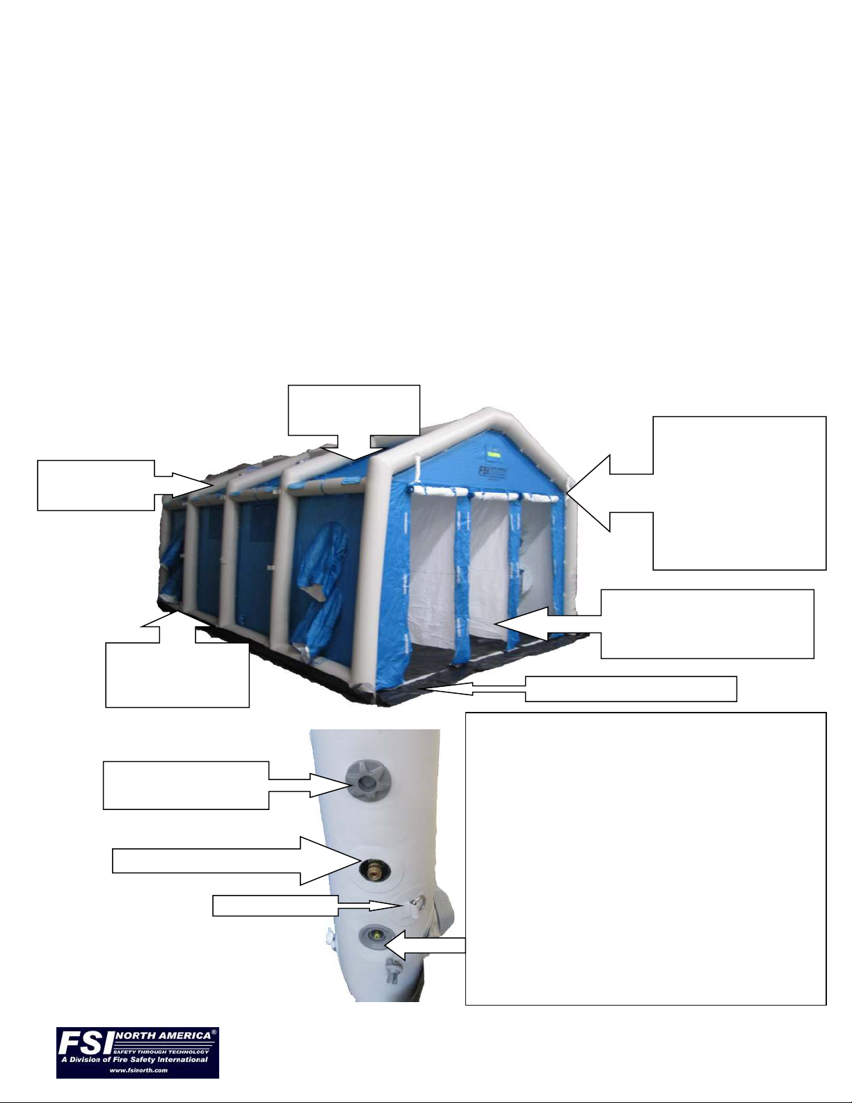
REMOVABLE
CANOPY
TIE DOWN ROPES AT
EACH CORNER TO
TIE FSI® SHELTER
OFF TO FIXED ITEMS
SUCH AS VEHICLES/
FENCES/POSTS/
POLES/OTHER IN
STRONG WINDS
DIRTY ENTRANCE DOOR
(CLEAN EXIT DOOR FROM
SHOWER AT OTHER END)
BUILT IN GROUNDSHEET
ATTACHED YET
REMOVABLE
FLOOR
INFLATABLE
STRUCTURE
FSI SHOWER/SHELTER DIAGRAMS
AIR BOTTLE INLET
ELECTRIC INFLATOR / DEFLATOR
INLET AND DUMP VALVE
INFLATION: Push in and quarter turn clockwise to lock
valve open. When unit fully inflated push in and quarter
turn counter clockwise to allow valve to pop up and
close. Your shower/shelter is now ready for use.
DEFLATION: To deflate, push in and quarter turn
clockwise to lock valve open. Air will rush out and unit
will begin to deflate. Ensure the tie down ropes are used
to assist the unit in returning to the ground by pulling
them toward each other allowing the unit to collapse into
its’ own footprint. Use the deflation end of the electric
inflator/deflator to ‘such’ the remaining air out of the
unit until flat to the naked eye. Then push in and quarter
turn counter clockwise to allow valve to pop up and
close.
SAFETY OVER
PRESSURE VALVE
O/D RING
7
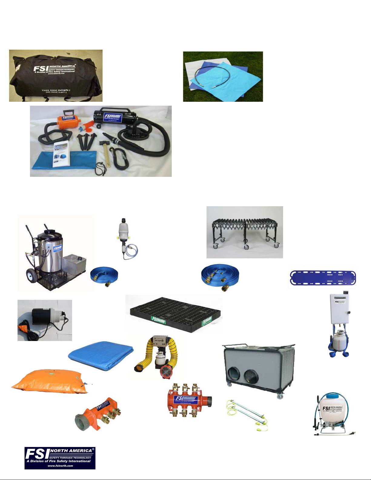
FSI® SHOWER/SHELTER PACKING LIST
FSI showers/shelters consist of the following items:
Showers/Shelters
in carry sleeve/bag
High Pressure Air inlet
hose and SCBA fitting
to fit all known scba air
cylinders and repair
material swatches
Full instructions for use, repair kit,
stakes, tie down ropes, inflator/deflator
(size depends on size of unit), and ham-
mer.
FSI® SHOWERS/SHELTERS
FSI showers/shelters are offered with multiple optional items with
a few examples as below:
Air Heaters
(F-ZHAF and
F-ZHAFD)
Waste Water
Pump
(F-WSP33AA)
Elevation
Grid
(F-TDMSPC)
Conveyor Systems
(F-RS shown)
Detergent Injection
System
(FSI HEAT 201)
Hand Sprayer
(F-HSP)
Water Heater
(FSI Heat 200A)
F-GH (50’) HOSES
F-GH35 F-GH503510
F-GH25 F-GH5025
F-GH10
F-MX1
(Spine Board/
Transfer Board)
HVAC
(F-DI35HP0100CM)
Manifolds
(F-MMU153,
F-MMU253,
F-MMU156,
F-MMU256) Stringable Lights
F-125-0500-STL
Heavy Duty Bladder Tanks
(F-HD150BT,
F-HD300BT,
F-HD600BT)
Ground Tarps
Asst. sizes
Water Heater
(F-ECC150WH)
8
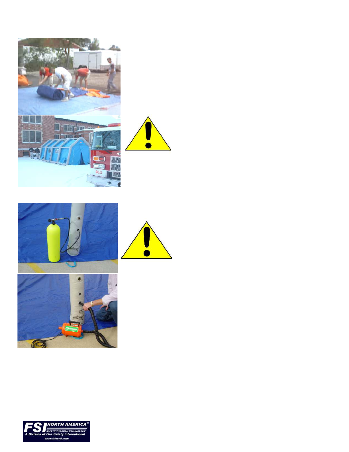
UNPACKING FSI® SHOWERS/SHELTERS
To unpack FSI® shower/shelter and if a pneumatic unit, make ready for inflation
Undo carry bag/sleeve and remove unit. If no groundsheet
or tarp is readily available, the carry sleeve/bag fully
flattened out can be used as a partial emergency
groundsheet to protect the shower/shelter.
Ensure surface is flat and free of sharp objects, place
groundsheet / tarp on ground (FSI® offers as an option),
then unroll FSI® unit either onto groundsheet or onto
ground carefully.
NOTE! LIFT - Do not drag on ground!
Place FSI® unit to suit all site and incident requirements,
ensuring entry/exit doors are aligned in right direction.
On-scene coordinator must make these decisions.
INFLATING FSI® SHOWERS/SHELTERS FOR USE
Follow all instructions located above the fill
valves on every unit EXACTLY.
If using an SCBA cylinder and the
supplied black color high pressure fill
hose with locking clip and fitting please
review those instructions carefully and
follow them exactly.
Follow all instructions located above the fill valves on every
unit EXACTLY.
If using the supplied inflator deflator use in the manner as
shown herein following all instructions located on the berms
of the unit.
Allow a steady, clean flow of air to inflate the unit. It will take approx. 45 seconds to 5+
minutes to inflate the unit (size of unit dependent) from an SCBA cylinder, and slightly
longer if using a compressor or the electric inflator/deflator. Remove/disconnect inflat-
or/deflator once unit is fully inflated.
NOTE! Support roof of FSI shelter as it inflates! (help unit stand) . In deflation mode en-
sure the tie down ropes are used to assist the unit in returning to the ground by pulling
them toward each other allowing the unit to collapse into its’ own footprint.
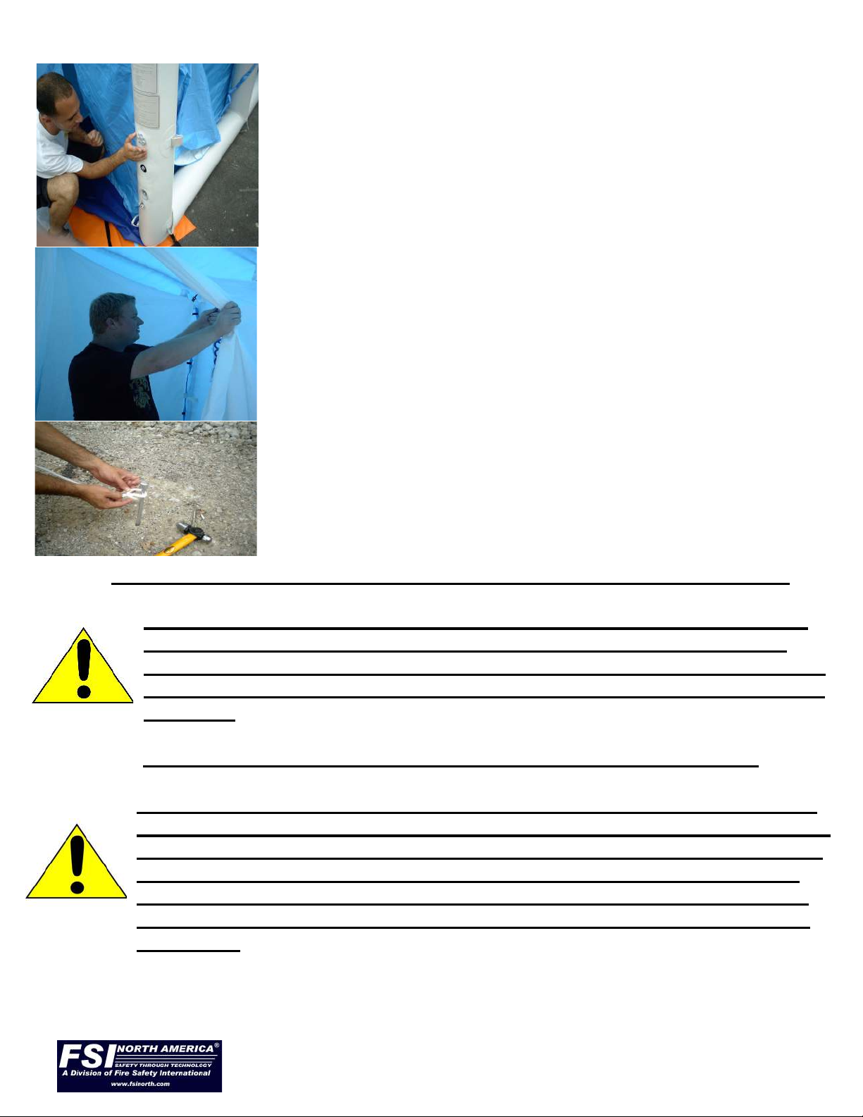
9
With on-scene coordinator oversight, carefully attach hose
to scba/dive air cylinder and lock hose to air berm D ring
using supplied locking clip. Then turn on cylinder air VERY
slowly. Then inflate unit until overpressure valve
operates - indicated by sound of escaping air (escaping air
can also be easily felt by hand. IMMEDIATELY turn off
compressed air supply. The overpressure valve will close
automatically when excess air has escaped from unit.
NOTE! Never cover/block the overpressure valve, as
the unit may become over pressurized and fail.
Make the following final checks:
Check that the unit is upright, that all valves are closed,
and no leaking is occurring. If, in the unlikely event a leak
is discovered, deflate unit and repair before using. (See
instructions for notes on how to repair punctures.)
In the event of/in case of windy conditions, always tie
off unit to the ground using supplied tie down ropes
and stakes, and/or lash to solid objects (e.g., vehicles).
OPERATING FSI UNIT - WATER INLET PRESSURE GUIDELINES
FSI Shower systems have all been designed to handle a maximum
incoming water pressure of approx. 55 psi (3.6 Bar). If the water
pressure coming into the FSI shower unit is unknown or will exceed
55 psi – FSI requires the use of a water pressure reducer – available
from FSI.
** INLET WATER PRESSURES in FSI Decon Shower Systems:
Each and every section of spray nozzle heads and multiple function
trigger guns is equipped with a shut off valve and a quick disconnect
feature. If you find the inlet water pressure is not capable of feeding
all water outlets with sufficient water pressure to provide a proper
shower – then shut off all shower heads not currently being used .
This will best ensure maximum water pressure is available where it
is needed.
INFLATION USING HIGH PRESSURE COMPRESSED AIR:
FSI® DAT® AND DAT® ‘QE SERIES’® DECON SHOWERS ARE ANSI 113 COMPLIANT.

10
FSI units have been designed for use by personnel with some knowledge or training in
decontamination procedures. On-scene coordinators must always determine correct use.
Proceed as follows:
Unzip / separate velcro closure doors at the entrance to the unit. The entrance is normally
the location nearest to the inflation/overpressure valves but this must be as determined by
on-scene coordinator.
At night, the relatively translucent construction and reflective striping above the doors and on
the berms of the FSI unit will allow light from external sources to illuminate the interior and
clearly show the entry and exit points.
STOWING FSI® SHOWER/SHELTERS:
If using Accessories such as air/water heaters/ decon
showers, disconnect and remove all showers, heating , air
cooling units, lights, elevation grids, and so forth from inside
the shower/shelter or in close proximity to.
Wipe up any residual water inside the unit, and make sure
interior is completely dry.
To deflate unit, make sure the entrance and exit doors are
unzipped and rolled up.
Ideally place one person or more at each end of FSI shelter;
then open the deflation/dump valve.
The FSI shower/shelter will rapidly deflate (usually within 1
minute or so). As the unit collapses, each person should pull
inwards on the end pillars, so the roof collapses neatly
on top of the lower part of the unit.
Ideally fold the shower/shelter back up exactly as received.
Failing that, fold the shower/shelter in three or more sections
starting at the end furthest from the deflation/dump valve.
This will further squeeze air from the unit.
HINT: It is best to use the supplied electric/inflator/deflator to
fully remove air from the unit, but not essential.
Place the carry bag/sleeve over the top of the folded unit,
then roll the unit over so the bag/sleeve is now the right side
up. Alternately fold the unit so the final melon roll fold places
the unit largely in the fully laid out carry bag/sleeve. Center
unit in carry bag/sleeve and pull/cinch straps tightly.
The FSI unit is now ready for transport and storage.
This manual suits for next models
22
Table of contents
Other FSI Shelter manuals

Popular Shelter manuals by other brands


Storage Canopy
Storage Canopy C3340R Assembly instructions

Frabill
Frabill ICE HUNTER 195 instruction manual

Shelters4Less
Shelters4Less SR1588 Assembly instructions

Sealey
Sealey Power Products GSS150819SD instructions

Crivit
Crivit 104155 Operation and safety notes

No Butts Bin
No Butts Bin SR1558-F Assembly instructions