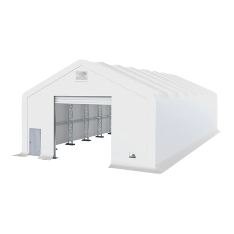
Mytee 3340 User manual

1
Container Shelter
Model 3340
W10.0xL12.0xH3.6m
(1.5m arch space)
Assembly Instructions
RECOMMENDED TOOLS

2
RECOMMENDED TOOLS
Equipment List
Speed Wrench
22#.23#.24#
Hammer (30lb)
Rope (12#)
Long Tape (50m)
Hammer Drill*1
Lifter*2
Crane*1
Forklift*1
Protective
equipment

3
YOU MUST READ THIS DOCUMENT BEFORE YOU BEGIN TO ASSEMBLE THE SHELTER.
Thank you for purchasing our shelter. When properly assembled and maintained, this product will provide years
of reliable service. These instructions include helpful hints and important information needed to safely assemble
and properly maintain the shelter. Please read these instructions before you begin.
If you have any questions during the assembly, contact Local dealer for assistance.
SAFETY PRECAUTIONS
. Wear eye protection.
. Wear head protection
. Wear gloves when handling metal tubes
. Use a portable GFCI (Ground Fault Circuit Interrupter) when working with power tools and cords.
. Do not climb on the shelter or framing during or after construction.
. Do not occupy the shelter during high winds, tornadoes, or hurricanes.
. Provide adequate ventilation if the structure is enclosed.
. Do not store hazardous materials in the shelter.
. Provide proper ingress and egress to prevent entrapment.
ANCHORING INSTRUCTIONS
Prior to assembling this shelter, please read the MUST READ document included with the shipment.
LOCATION
Choosing the proper location is an important step before you begin to assemble the structure.
The following suggestions and precautions will help you determine whether your selected location is
the best location.
. Never erect the structure under power lines.
. Identify whether underground cables and pipes are present before preparing the site or anchoring
the structure.
. Location should be away from structures that could cause snow to drift on or around the building
. Do not position the shelter where large loads such as snow and ice, large tree branches, or other
overhead obstacles could fall.
SITE
After choosing a location, proper preparation of the site is essential. The following site characteristics
will help ensure the integrity of the structure.
. The support structure must be level to properly and safely erect and anchor the frame.
. Drainage: Water draining off the structure and from areas surrounding the site should drain away from
the site to prevent damage to the site, the structure, and contents of the structure.
WARNING: The individuals assembling this structure are responsible for designing and furnishing
all temporary bracing, shoring and support needed during the assembly process. For safety reasons,
those who are not familiar with recognized construction methods and techniques must seek the help
of a qualified contractor.

4
Parts List of SS334012R-9(L12xW10xH3.6m)
Part
Code
Description
Parts Drawings
Q'ty
1
Top arch pipe
9
2
Middle bent arch pipe
18
3
Lower bent pipe
18
4
Purlins
40
5
Bracing pipe
12
6
Mount rail-1
2
6A
Mount rail-1A
2
7
Mount rail-2
2
7A
Mount rail-2A
2
8
Mount rail-3
2
9
Tension pipe
2
10
connection plate for base rails
16
11
Angle seat
36
12
Clamps for fixing base rails
4
13
Channel steel clamps
18
14
Φ75 clips with M10*50 bolt
24
15
M10*90mm bolt for swaged pipe connection
108+1
5
16
M12*100mm carriage bolt for purlins
connection
45+6
17
M12x100 bolt for square pipe connection
32+4
18
40 plastic plug
4

5
19
1.5'' ratchet with tension straps
18
20
75CM Nylon zipper for roof cover
100
21
6# ropes 16m/pcs 4pcs
1
22
Corner bracket of 1.5inch ratchet
4
23
Tech screw M8*25
8+2
24
Tech screw M8*40
36+6
25
Roof cover
1

6
CONTAINERS LOCATION:
Note: The containers must be firmly fastened to the ground before installation
The distance between 2 x 40ft GP container is 32’10’’ , make sure they are level and square to
each othe.
The diagonal distance from corner point to opposite corner point is 51’9’.

7
Instruction for steel frame
1. Connect the square steel tube base rails No.6, No.7, No.8, No.7A and No.6A on left and right
container roofs. Using the connection plates #10 with bolt M12x100 with #17 with 2pcs
WASHERS.
Two kinds of methods to fix base rails as the below drawings for option:
Option A: Using base rail clamps No.13 with tech screws No.24 to fix the square tube rails to the
top of container without any welding works as the below figure, the two ends of base rails is fixed
to the casting corners of container with No.12 corner clamps.
Option B: The two ends of base rails is fixed to the casting corners of container with No.12
corner clamps.Welding angle seat No.11 to fix the square tube rails on the top of container.

8
2. Connect the Bent Joist (No.1, 2, 3) by bolt M10x90 (No.15) to be one arch. Put one end of the
arch into the mount rail spigot and fasten it by bolt M10x90 (No.15), then try to put the other
end to opposite rails.

9
Purlins and Bracing Tubes Installation
3. When 2 arches are in place, connect purlins (No.4) between them by carriage bolt M12x100
(No.16). Please note the direction of the bolt, do not leave the shaft outside where the fabric
will rest. By this way, one arch and purlins between it in turn, frames are installed.
4. Install bracing tube (No.5) by Clip (No.14).
Note: Before install the arch, please install the clip firstly.

10
NOTE: DO NOT install the cover onto the frame of the dome shelter in high wind conditions. A
slight breeze is the most advantageous for cover installation. To take advantage of the breeze, pull
the cover up over the arches with the breeze blowing in the cover like a sail filled with air.
1. Put the cover EVENLY, CAREFULLY AND SLOWLY on the frame. Insert the Tension Tubes
(No.9) into the cover pipe pockets and loosely secure the strap (No.19) in the winch on square
tube rails. DO NOT TIGHTEN. Adjust the cover so that it is square and evenly centered on the
frame.
Note: The end flaps must overhang evenly at both ends.
1. Firstly use nylon tie (No.20) to fix the two ends of roof cover to end arches at intervals. Then
use Rope (No.21) to tighten roof cover to end arches. The rope should be cut as your requirements
when using. When the cover is tidy and ready, drive the winch tie down forth and back and then
roof cover is tightened.
2. Pull the band inside the roof cover (four corners) by Winch (No.22). The winches No.22
should be welded to container or fastened with self-screws No.23.
Note: DO NOT LEAVE COVER UNATTACHED UNDER ANY CIRCUMSTANCES until
the final assembly and tightening has been completed.
The process is quite easy. But some tightening adjustments will be necessary to produce a
flat, tight roof cover.
Instruction for Roof Cover Attached

11
The Installation is completed!
Table of contents
Other Mytee Shelter manuals
Popular Shelter manuals by other brands

Shelters4Less
Shelters4Less SR1556 Assembly instructions

TMG
TMG TMG-DT3081-PRO product manual

TMG
TMG TMG-CP1220F product manual

Kiwi Camping
Kiwi Camping KC074-818 Pitching instructions

Blackrock Microsystems
Blackrock Microsystems 9027301 owner's manual

IAE
IAE LONGTON SMOKING SHELTER Assembly & Maintenance Manual