FSR DV-T6SS4K-41A User manual

2/ 78
Feature List
4 x HDMI video inputs:
HDMI inputs support up to 4Kx2K @60Hz
Supports multiple HDMI output resolutions, such as
4Kx2K @60Hz, 4Kx2K@30Hz and 1080P.
Independent automatic or fixed scaler setting per input.
HDCP 2.2 & 1.4 compliant.
Provides HDMI audio extraction, via 3.5mm jack.
Audio embedding via front panel 3.5mm input jack.
User -friendly web GUI operation and setup.
Simple Front Panel direct input select controls.
Three control modes; Manual, Auto Last Connect and Auto
Input Scan.
Remote Control by switch with lamp feedback, LAN (Web GUI
and TCP), or RS232
Supports CEC, Serial Display control and Custom Screen
Saver im ages and videos.
Compact enclosure, 1U height, rack mountable design

3/ 78
Table of Contents
Getting Started ......................................................................................................................................... 5
Panel Layout ...................................................................................................................................... 5
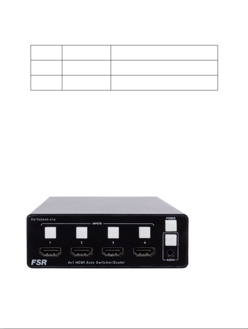
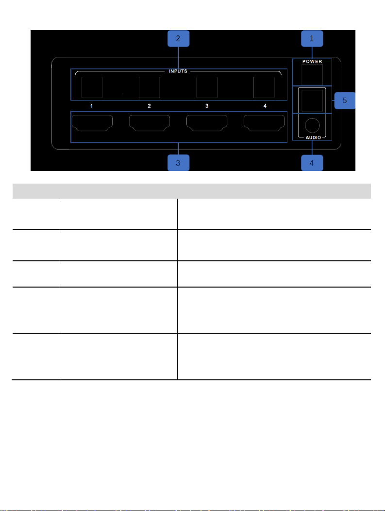
Front Pan el ................................................................................................................................... 5
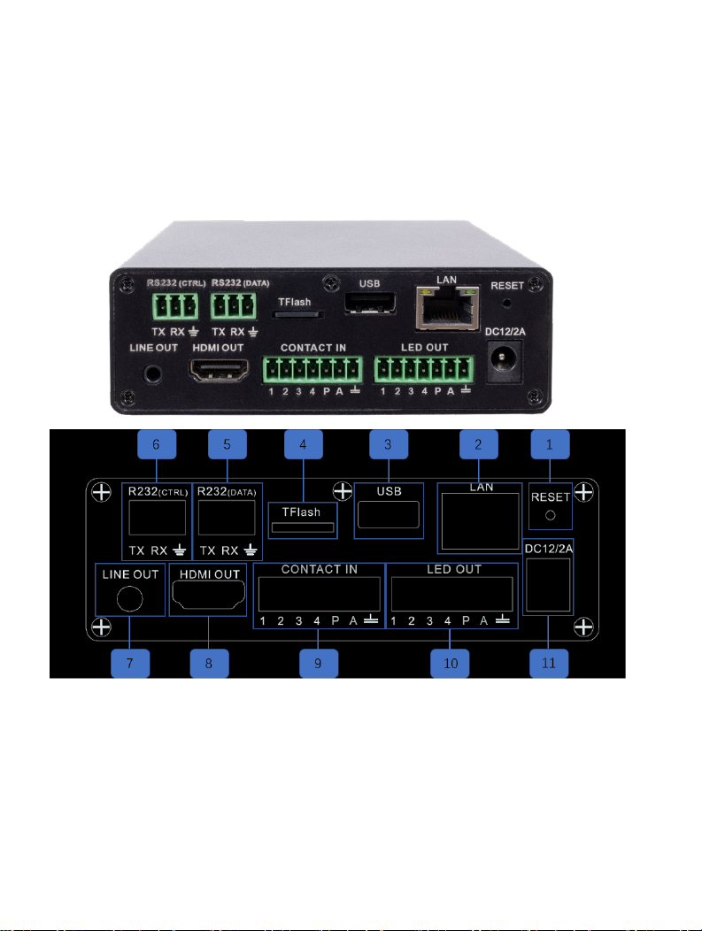
Rear Panel.................................................................................................................................... 7
Power Cord and Adapter .......................................................................................................... 10
Installation......................................................................................................................................... 11
How to Connect the DV-T6SS4K-41A Multi-format Presentation Scal er Switcher ............ 11
Wiring Diagram .......................................................................................................................... 12
Operating ................................................................................................................................................ 12
Display On/Off .................................................................................................................................. 12
Video Source Selection Switch ...................................................................................................... 14
Audio Selection Mode Switch......................................................................................................... 14
Output Resolution ............................................................................................................................ 15
Advanced Settings ................................................................................................................................. 17
RS232 Setting .................................................................................................................................. 17
IP Setting .......................................................................................................................................... 19

4/ 78
Command List .................................................................................................................................. 20
WEB Setting ..................................................................................................................................... 51
Gener al Settings ........................................................................................................................ 53
Advanced Settings ..................................................................................................................... 60
EDID Managemet ...................................................................................................................... 64
St andby Pl ayer ........................................................................................................................... 67
External Control ......................................................................................................................... 69
Update......................................................................................................................................... 74
Other........................................................................................................................................................ 75
Factory Reset ................................................................................................................................... 75
F/W Update ...................................................................................................................................... 76
Electrical Parameters ...................................................................................................................... 77
Version log:
Version Revise time Description
0.1 2018, Mar. 28th Created
0.2 2018, Jun. 1st Updated the Web GUI

5/ 78
1.0 2019, July, 3rd Updated product design pictures
1.1 2020, June, 8th Updated product rear panel design
1.2 2020, June, 11th Updated command list
Getting Started
Panel Layout
Front Panel

6/ 78
ID Name Description
1 Display On/Off
Turns the output on and off, sends out CEC and Serial
display control commands if setup in the GUI.
2 Input Buttons and Indicator
Input select buttons used to select inputs 1~4. The indicators
display the s elected video audio input.
3 HDMI input 1~4 HDMI video input connectors support four 4K 60Hz sources.
4 Line in
Stereo analog audio input, Connect a 3.5mm mini-stereo
cable from the Line Out jack on the audio source device to
this jack.
5 Audio Buttons and Indicator
Audio mode sel ection. The button and indicator allows the
user to r eplace the output HDMI audio with the analog audio
connected to the front 3.5mm jack.

7/ 78
Rear Panel

8/ 78
ID Name Description
1 Reset Restores the unit to the factory default setting.
2 LAN
Connect an Ethernet cable between
this jack and a LAN to use the web GUI or IP control.
Refer to RS-232 and IP Configuration for
more information on setting up IP control.
3 USB USB port for upgrading or charging.
4 T-Flash T-Flash port for standby player.
5 RS232 (Data)
Connect an RS232 cable from this port to an RS232-compliant
device to automatically control the device when the switcher
turns on or off. See RS232 and IP Configuration for information
on setting up RS232 control.
6 RS232 (Ctrl)
Connect an RS232 cable from this port
to a third-party control system to control the scaler switcher. See

9/ 78
RS232 and IP Configuration for more information on setting up
RS232 control.
7 Line Out
Analog stereo audio output, Connect a 3.5mm mini-stereo c able
from this jack to the line-in jack of a multimedia system .
8 HDMI output
Connect an HDMI cable from this port to an
HDMI display.
9 Key - Input Contact closer Input mirrors the front button functions.
10 LED - Output LED Drive Voltage mirrors the front button LEDs.
11
DC Power
Connector
Connect the original AC-DC power adapter to this receptacle.
Connect the included AC power cord to the original power
adapter, then connect the plug to an available electrical outlet.

10 / 78
Power Cord and Adapter
The DV-T6SS4K-41A multi-form at present ation scaling switcher adopts international standard
12V AC-DC power adopter.
Voltage: 12V, Max Current: 4A.
Attention: A variety of different country specific plug adaptors are included with the standard
package.

11 / 78
Installation
How to Connect the DV-T6SS4K-41A Multi-Format Presentation Scaler Switcher
1. Connect four 4K or HD HDMI sources to the input ports (HDMI 1 - HDMI 4) on
the DV-T6SS4K-41A.
2. Connect a 4K or HD display to the HDMI Output port on the DV-T6SS4K-41A.
3. OPTIONAL: Connect analog audio to the audio line-in port on the DV-T6SS4K-
41A.
4. OPTIONAL: Connect an RS-232 cable from the RS-232 (Ctrl) port on the DV-
T6SS4K-41A to the RS-232 connector on the serial controller.
5. OPTIONAL: Connect one 3.5mm mini-stereo cables from the jacks on the DV-
T6SS4K-41A to the line in jack of a multimedia system.
6. OPTIONAL: Connect an RS-232 cable from the RS-232 (Data) port on the DV-
T6SS4K-41A to the RS-232 connector on the device, which is to be controlled by
the DV-T6SS4K-41A.
7. OPTIONAL: Connect an ethernet cable from the LAN port on the DV-T6SS4K-

12 / 78
41A to a Local Area Network (LAN).
8. Connect the AC power cord to the AC-DC adapter and connect the plug to an
available electrical outlet.
Wiring Diagram
Operating
Display On/Off
The “Power” button on the front panel, turns the DV-T6SS4K-41A output on and off and
optionally will send an HDMI CEC turn-on or turn-off command or serial command to the display.

13 / 78
The indicator will turn green when the DV-T6SS4K-41A output turns on and optionally sends a
HDMI CEC turn-on command to the display; this is shown as follows.
This indicator will turn off when the DV-T6SS4K-41A output is shut off and optionally sends an
HDMI CEC turn-off command to the screen; this is shown as follows.

14 / 78
Video Source Selection Switch
1) Use the INPUT buttons on the front panel or web GUI to switch between input source
devices.
2) HDMI 1 s elected for output; this is shown as follows.
Audio Selection Mode Switch
1) Use AUDIO button on the front panel or web GUI to replace HDMI output audio with
Analog source.

15 / 78
2) Analog audio-in mode enabled, this is shown as follows.
3) Embedded HDMI mode, this is shown as follows.
Output Resolution
HDMI output resolutions support multiple modes. Use the Web GUI to configure via the
drop-down menu.
1) Auto

16 / 78
2) 3840x2160@60Hz
3) 3840x2160@50Hz
4) 3840x2160@30Hz
5) 1920x1200@60Hz
6) 1920x1080@60Hz
7) 1920x1080@50Hz
8) 1280x720@60Hz
9) 1280x720@50Hz
10) 1680x1050@60Hz
11) 1600x1200@60Hz
12) 1600x900@60Hz
13) 1400x1050@60Hz
14) 1400x900@60Hz
15) 1366x768@60Hz
16) 1360x768@60Hz
17) 1280x1024@60H
18) 1280x800@60Hz
19) 1280x768@60Hz
20) 1024x768@60Hz
21) 800x600@60Hz

17 / 78
Auto means that it outputs the HDMI resolutions based on the EDID information read
from the display device.
Advanced Settings
RS232 Setting
RS-232 port:

18 / 78
DCD
RXD
TXD
DTR
GND
DSR
RTS
CTS
R1
1
2
3
4
5
6
7
8
9
DCD
RXD
TXD
DTR
GND
DSR
RTS
CTS
R1
1
2
3
4
5
6
7
8
9
RS-232
Device
4x1
Switcher
Connect to RXD, TXD, GND only
RS232 Settings:
Description Setting
Baud rate 115200
Data bits 8
Parity None
Stop bits 1
Hardware flow control None
Notes: For more information about serial command, see the command list chapter.

19 / 78
IP Setting
The DV-T6SS4K-41A supports web control and TCP control. Ther e ar e two methods to obtain
the IP address:
1. Obtain the IP address and port number via the information from the on-screen
display (OSD).
2. Send an RS232 command to obtain the IP address, for example, send RS232
commands like “ #NET-CONFIG-ALL?” or “ #NET-CONFIG-IP?”
The following explains the 1st method:
Obtain the IP address and port number via the information from the OSD (on-screen display).
IP address and port number can always be obtained from OSD. When there is no signal,
the following OSD is shown on the bottom of the screen:
Or when the picture is displayed, the IP information is displayed on the bottom area above the
window.

20 / 78
The IP address is 192.168.1.150 and the port number is 23.
Command List
The DV-T6SS4K-41A c an be controlled or operated through the commands from RS232 or TCP.
Command head: #
Length: <=255
Ending: 0x0D
Band rate: default 115200
,
all commands are added to the end of the "<CR>“ (hex is 0x0D)
Commands Type
Command
Sample
Description Response Sample Remark
General
Control
#HANDSHAKE get
#HANDSHAKE<C
R>
protocol
handshaking
<SUCCESS>
#FACTORY set #FACTORY<CR>
reset to factory
default
configuration
<FACTORY
SUCCESS>
#FW-VERSION get
#FW-VERSION?
<CR>
get device
firmware version
<FW-VERSION
0.01.001>
Table of contents
Other FSR Switch manuals

FSR
FSR DV-HSW-21CEC User manual

FSR
FSR DV-HSW4K-41 User manual

FSR
FSR TN-2105EQA User manual

FSR
FSR Compass Plus CP-100 User manual

FSR
FSR CP-100 User manual

FSR
FSR DV-HSW-21A User manual

FSR
FSR DV-HDSS-41-TX User manual

FSR
FSR RN-410 Series User manual

FSR
FSR Compass 3.0 User manual

FSR
FSR Eagle 200 User manual