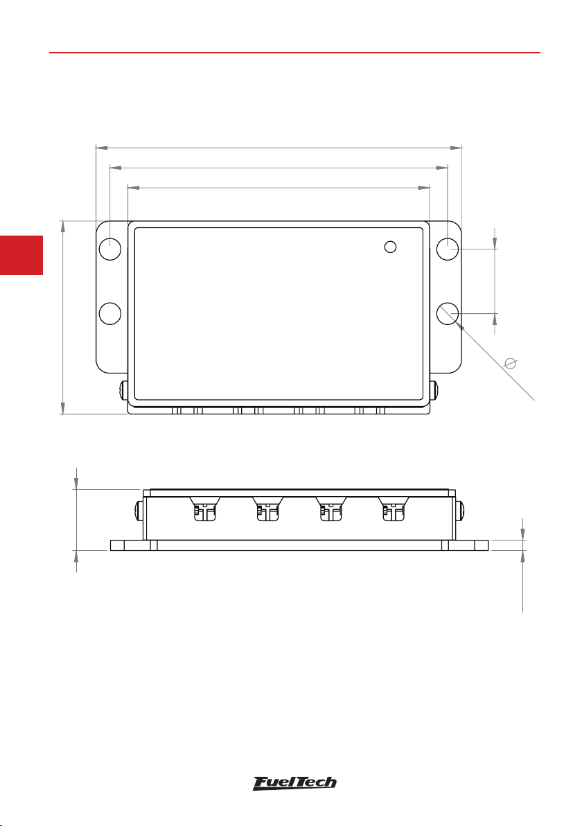
FuelTech EGT-4 CAN User manual

OWNER’S MANUAL
MANUAL DO USUÁRIO
C
M
Y
CM
MY
CY
CMY
K
Manual - EGT-4 CAN v1.01 - Print.pdf 1 7/3/2020 9:58:35 AM


3
EN
EGT-4 CAN
1. Index
2. Presentation .......................................................................................................... 4
3. Warranty terms ...................................................................................................... 5
4. Installation ............................................................................................................ 6
4.1 Dimensions (in)................................................................................................ 6
4.2 Wiring Harness with Power FT line ................................................................... 7
5. Setup.................................................................................................................... 8
5.1 Touchscreen interface setup ............................................................................ 8
5.2 FTManager setup ............................................................................................ 8
6. Mounting template (in).......................................................................................... 10

4
EN
EGT-4 CAN
2. Presentation
The EGT-4 is a 4 channel K type thermocouple conditioner compatible with
FTCAN 2.0 protocol, Which allows it to send the sensor readings to the Power
FT product line.
It is generally used for individual cylinder exhaust gas temperature but can
also be used for air/engine temperature or to replace analog sensors and
free up analog inputs.
Characteristics
• Power Supply: 7 to 32 Volts
• Current draw: 0.05A
• Temperature range reading: 32 - 1830 F
Package contents
• Instructions Manual
• EGT-4 CAN conditioner
Recommended sensor length when the EGT-4 is installed on the rewall.
4 cylinder 6 cylinder V8 Small Block V8 Big Block
1 x 36” 1 x 42” 2 x 36” 2 x 42”
1 x 30” 1 x 36” 2 x 30” 2 x 36”
1 x 24” 1 x 30” 2 x 24” 2 x 30”
1 x 18” 1 x 24” 2 x 18” 2 x 24”
2 x 18”

5
EN
EGT-4 CAN
3. Warranty terms
The use of this equipment implies in total accordance with the terms described
in this manual and exempts the manufacturer from any responsibility regarding
product misuse.
This product must be installed and tuned by specialized auto shops
or professionals with experience on engine tuning.
The oversight of any of the warnings or precautions described in this manual
can cause engine damage and lead to warranty void of this product warranty.
Before starting any electrical installation, disconnect the battery.
This product is not certied for aeronautic purposes or any ying vehicles, as
it has not been designed for such applications.
In some countries where an annual inspection of vehicles is enforced, no
modication in the OEM ECU is permitted. Be informed about local laws and
regulations prior to the product installation.
Important warning for proper installation
Always remove and insulate unused wires. NEVER roll up excess
wiring as this may create an antenna that captures electromagnetic
interference that may generate product malfunction.
Limited Warranty
This product warranty is limited to one year from the purchase date, only
covering manufacturing defects and requiring purchase invoice presentation.
Damages caused by misuse of the unit are not covered by the warranty.
Warranty void analysis is done exclusively by FuelTech technical support team.
WARNING
Tampering or removing the product warranty seal will void the
product warranty.
Manual Version 1.0 – July/2020

6
EN
EGT-4 CAN
4. Installation
Installation must be performed with the wiring and battery disconnected. It’s
very important that the wiring harness be as short as possible and to cut off
all excess wiring. Never roll up unused wiring. These measurements will avoid
problems with electromagnetic interference, common in every electronic
equipment.
The wiring harness must be protected from sharp edges that may damage
wires and cause short-circuits. Pay attention when passing the wiring harness
through holes, always using rubber shields or other kind of wire protection. In
the engine bay, route the wiring through places that aren’t exposed to excessive
heat and won’t get close to moving parts of the engine. Plastic covers are
recommended for the wiring harness.
4.1 Mounting
The EGT-4 must be mounted to a at surface of the vehicle using the holes in
the side aps. The EGT-4 has a safety lock for the thermocouple connectors,
to lock it, follow the steps described below.
a - Loosen the two side screws (1) of the EGT-4 lock (2) and pull it out
b - Insert the K-type thermocouple connector on EGT-4
c - Place thermocouple cable tting in the lock
d - Push the lock until it touches the thermocouple connector and tighten
the two side screws
1
1
2

7
EN
EGT-4 CAN
4.2 Wiring Harness with PowerFT ECU’s
A - Black wire - Ground
B - Red wire - Switched 12V
1 - Male connector (rear view)
2 - Female connector (rear view)
3 - Terminator male connector (rear view)
4 - White/Black wire - CAN LOW - pin 3
5 - White/red wire - CAN HIGH - pin 4
6 - Any other FuelTech CAN device, like WB-O2 Nano or FTSPARK
NOTES
- The use of the terminator (3) is mandatory for the CAN network
correct functioning.
- When assembling the thermocouple, always use compensated
connectors. The yellow from the sensor is the positive terminal (+) (narrow
pin) and the red wire is the negative terminal (-) (wide pin).
IMPORTANT
If longer wires are needed in order to place the thermocouple,
always use compensated connectors (male and female) or pre-
made thermocouple extensions.
Use the same wire type if a longer wire for the sensor is needed.
The splice, the use of a compensate male and female connector
specic for type K thermocouple is mandatory.
4
3
13457
26
10 12 13
8911
14 16 17
15 18 19
20 22 25 26
21 23 24
13457
26
10 12 13
8911
14 16 17
15 18 19
20 22 25 26
21 23 24
2
1
4
3
1
2
3
5
BA
4
FTCAN 2.0
equipment 6
NOTE
Extension Harness sold separately.

8
EN
EGT-4 CAN
5. Setup
The CAN communication can be congured through the FTManager software
or through the touchscreen interface.
5.1 Touchscreen interface setup
Navigate to “sensors and calibration” and then to the “EGT” option. Select the
cylinder or cylinder bank for the installed thermocouple and then specify the
input that is used. For the CAN Network select option “CAN 2.0”. Up to four
EGT-4 units are supported on the same FTCAN network.
5.2 FTManager setup
Click the “CAN Network” (1) button on the top icon bar. A list of all the
equipments connected to the CAN network will be displayed.
1
EGT
Ge ralne
Left Bank Right Bank
Cylinder 1
Cylinder 5
Cylinder 9
Cylinder 2
Cylinder 6
Cylinder 10
Cylinder 3
Cylinder 7
Cylinder 11
Cylinder 4
Cylinder 8
Cylinder 12
EGT
Ge ralne
Left Bank Right Bank
Cylinder 1
Cylinder 5
Cylinder 9
Cylinder 2
Cylinder 6
Cylinder 10
Cylinder 3
Cylinder 7
Cylinder 11
Cylinder 4
Cylinder 8
Cylinder 12
C2/ylinder 13
None
Input selection
White Avaliable4:
White2-2: Step
White Air Conditioning3:
White O2 General1:
Clindrye2 2/3
Select the sensor type
ETM-1
Custom
Clindr 2ye3/3
Input valueOutput value
Sensor offset
+10,7
56,0
°C °C
Reading
Clindr2/ye13
White Avaliable5:
Input selection
CAN 2.0
WhiteAvaliable7:
White Avaliable8:
WhiteAvaliable6:
From
Equipment
CAN EGT
EGT-4 A
2
Channel
Cylinder 2 3/XX
Navigate to the CAN Communication menu under Sensors and Calibrations
menu.
Click on the channel you want to setup, a new window will open with all
available sensors. Select an option, click the OK button, and write to the ECU.
After associating the channels, check the CAN Network menu (1) to see a list
of all the sensors set on the EGT.

9
EN
EGT-4 CAN
5.3 Connecting more than one EGT-4 on the CAN network
Up to four EGT-4s can be connected to the same FTCAN network. However
it is necessary to identify each one on the CAN network. All the EGT-4s come
from the factory set as EGT-4s A. In order to add another EGT-4s on the same
network, follow the procedure described below:
a - Connect all modules on the CAN network
b - Open the CAN Network menu (1) as shown on the previous page
c - Note that on the left of this window there is only one EGT being shown
d - Right below there are settings for this EGT, in the “serial:” box all EGTs that
are on the network will be listed, even those that are not being shown on
the left, select the serial you want to identify and click the identify button,
the LED on the EGT-4 will blink 3 times to identify which EGT-4 selected
e - The next step is to click on the “Change to:” and change the ID of the
EGT-4, and click write button, note that as of now there are more than
one EGT-4 being shown on the left of the screen
f - Repeat this procedure for the other EGTs
5.4 Status LED
On: EGT On and CAN Network connected
Blinking: EGT On and CAN Network Disconnected

10
EN
EGT-4 CAN
6. Mounting template (in)
2.29
0.26
0.76
3.57
4
4.33
0.7
0.12

1
PT
EGT-4 CAN
1. Índice
2. Apresentação........................................................................................................ 2
3. Termo de garantia.................................................................................................. 3
4. Instalação ............................................................................................................. 4
4.1 Dimensões (mm) ............................................................................................. 4
4.2 Conexão elétrica com linha Power FT .............................................................. 5
5. Conguração......................................................................................................... 6
5.1 Através da tela da interface touchscreen .......................................................... 6
5.2 Através do software FTManager: ..................................................................... 6
6. Gabarito de xação (mm) ....................................................................................... 8

2
PT
EGT-4 CAN
2. Apresentação
O EGT-4 CAN é um condicionador para termopar tipo K de 4 canais compatível
com protocolo FTCAN 2.0 que permite enviar as leituras dos sensores para
a linha Power FT.
Em geral utilizado para medir a temperatura dos gases do escapamento
individual por cilindro, mas pode também ser utilizado para medir temperaturas
de ar e temperatura do motor, substituindo sensores analógicos e liberando
entradas analógicas.
Características
• Alimentação: 7 a 32 Volts;
• Consumo: 0,05A;
• Faixas de leitura de temperatura: -50 - 1000 ºC;
Conteúdo da embalagem
• Manual;
• Módulo;
Comprimento de sensores recomendados quando EGT-4 instalado na parede corta fogo
4 Cilindros 6 Cilindros V8 Small Block V8 Big Block
1 x 910 mm 1 x 1066 mm 2 x 910 mm 2 x 1066 mm
1 x 760 mm 1 x 910 mm 2 x 760 mm 2 x 910 mm
1 x 610 mm 1 x 760 mm 2 x 610 mm 2 x 760 mm
1 x 450 mm 1 x 610 mm 2 X 450 mm 2 X 610 mm
2 x 450 mm

3
PT
EGT-4 CAN
3. Termo de garantia
A utilização deste equipamento implica na total concordância com os termos
descritos neste manual e exime o fabricante de qualquer responsabilidade
sobre a utilização incorreta do produto. Leia todo o Manual do produto antes
de começar a instalação.
Este produto deve ser instalado e regulado apenas por ocinas
especializadas ou pessoas capacitadas e que tenham experiência
com regulagem e preparação de motores.
A desobediência a qualquer um dos avisos e precauções descritos neste
manual pode causar danos ao motor e perda da garantia deste produto.
Acerto incorreto do produto pode causar danos ao motor.
Antes de começar qualquer instalação elétrica desconecte a bateria.
Este equipamento não possui certicação para utilização em aeronaves ou
assemelhados, portanto não é prevista para este m.
Em alguns países que realizam inspeção veicular anual não é permitida
qualquer modicação no sistema de injeção original.
Informe-se antes da instalação
Aviso importante para a correta instalação
Sempre corte as sobras de o – NUNCA enrole o pedaço sobrando,
pois isso se torna uma antena captadora de interferências e pode
gerar o mau funcionamento do equipamento.
Garantia Limitada
A garantia deste produto é de um ano a partir da data da compra e cobre
apenas defeitos de fabricação.
Defeitos e danos causados pela incorreta utilização do produto não são
cobertos por garantia.
ATENÇÃO
Esse produto possui lacre de garantia. Qualquer tentativa de
desmontar o produto fora da fábrica causará rompimento do
mesmo, invalidando a garantia de forma permanente.
Manual versão 1.0 – Julho/2020

4
PT
EGT-4 CAN
4. Instalação
A instalação deve ser realizada com o chicote elétrico desconectado do
módulo e com a bateria desligada do veículo. É muito importante que o chicote
seja do menor tamanho possível e sempre que algum o estiver sobrando
deve-se cortar o pedaço excedente. Nunca enrole as sobras de qualquer
o do chicote. Este cuidado evita problemas de interferência, comuns em
qualquer equipamento eletrônico.
O chicote elétrico deve ser protegido de contato com partes aadas da lataria
que possam vir a danicar algum o e causar curto-circuito. Preste atenção
especial na passagem por furos, sempre colocando borrachas ou outras
proteções. No cofre do motor, passe os os por locais onde não recebam
calor excessivo e não obstruam nenhuma peça móvel do motor. Procure
utilizar capas plásticas nos chicotes.
4.1 Fixação
O EGT-4 deve ser xado em uma parte plana do veículo através dos furos nas
abas laterais. O EGT-4 conta com uma trava de segurança para os conectores
dos termopares, para travar execute os passos descritos a seguir.
a - Afrouxe os dois parafusos laterais (1) da trava (2) do EGT-4 e puxe-o
para fora;
b - Encaixe o conector do termopar tipo K no EGT-4;
c - Posicione o cabo do termopar no encaixe da trava;
d - Puxe a trava até encostar no conector do termopar e aperte os dois
parafusos laterais.
1
1
2

5
PT
EGT-4 CAN
4.2 Conexão elétrica com linha Power FT
A - Fio preto - Terra;
B - Fio vermelho - Positivo;
1 - Conector macho (vista traseira);
2 - Conector fêmea (vista traseira);
3 - Conector macho terminador (vista traseira);
4 - Fio amarelo/azul - CAN LOW - pino 3;
5 - Fio vermelho/branco - CAN HIGH - pino 4;
6 - Equipamento Compatível com FTCAN 2.0, WB-O2 Nano ou FTSPARK;
NOTAS
- O uso do terminador (3) é obrigatório para um funcionamento correto
da rede CAN.
- Ao montar o termopar tipo K em um conector compensado, lembre-
se que o o amarelo do termopar vai conectado ao terminal positivo (+)
(pino mais estreito), já o o vermelho vai conectado ao terminal negativo
(-) (pino mais largo).
IMPORTANTE
Caso seja necessário estender os fios dos termopares, use
sempre conectores compensados com o mesmo tipo de o,
ou, use extensões de termopares já prontas, especícas para
termopares tipo K.
4
3
13457
26
10 12 13
8911
14 16 17
15 18 19
20 22 25 26
21 23 24
13457
26
10 12 13
8911
14 16 17
15 18 19
20 22 25 26
21 23 24
2
1
4
3
1
2
3
5
BA
4
Outro equipamento
FTCAN 2.0 6
NOTA
Chicote de extensão pode ser comprado separadamente, solicite em
nosso setor comercial pelo código 6497 (Chicote EGT-4 CAN).

6
PT
EGT-4 CAN
5. Conguração
Pode-se congurar a comunicação CAN através do software FTManager ou
através da interface touchscreen.
5.1 Através da tela da interface touchscreen
Navegue até “Sensores e Calibração” e então até a função “EGT”. Selecione
o cilindro ou bancada que será instalado o termopar, especique a entrada
a ser utilizada. Para rede CAN, selecione a opção “CAN 2.0”. É possível
congurar até 4 módulos de EGT-4 para cada veículo.
EGT 1/3
Geral
Bancada esquerda Bancada direita
Cilindro 1
Cilindro 5
Cilindro 9
Cilindro 2
Cilindro 6
Cilindro 10
Cilindro 3
Cilindro 7
Cilindro 11
Cilindro 4
Cilindro 8
Cilindro 12
Cilindro 2 2/xx
Nenhuma
Selecione a entr
ada desejada
Branco 4: Disponível
Branco 2: Two Step
Branco 3: Botão do ar condicionado
Branco 1: Disponível
Cilindro 2 3/xx
Tipo de sensor de temperatura
ETM-1
Customizado
Cilindro 2 4/XX
Valor de entrada Valor de saída
Ajustar offset do sensor
+10,7
56,0
°C °C
Leitura atual
Cilindro 2 2/xx
Branco 5: Disponível
Selecione a entrada desejada
CAN 2.0
Branco 7: Disponível
Branco 8: Disponível
Branco 6: Disponível
Origem
Equipamento
CAN EGT
EGT-4 A
2
Canal
Cilindro 2 3/XX
EGT 1/3
Geral
Bancada esquerda Bancada direita
Cilindro 1
Cilindro 5
Cilindro 9
Cilindro 2
Cilindro 6
Cilindro 10
Cilindro 3
Cilindro 7
Cilindro 11
Cilindro 4
Cilindro 8
Cilindro 12
5.2 Através do software FTManager:
Clique no botão “Rede CAN” (1) na barra de botões. Ali estarão listados todos
os equipamentos conectados à rede CAN da FT. Se o EGT-4 não aparecer
nesta tela verique a ligação do mesmo.
1
Navegue até o menu Comunicação CAN na função “Sensores e Calibração”,
clique sobre o canal que se deseja congurar, após abrirá uma nova janela
com todos os canais disponíveis para associação, selecione uma opção e
clique no botão OK, feito isso associe os demais canais e grave na ECU.
Após associar os canais desejados verique no menu Rede CAN (1) se esses
canais aparecem na aba detalhes do produto.

7
PT
EGT-4 CAN
5.3 Conectando mais de um EGT-4 na Rede CAN
É possível congurar até 4 EGTs em uma mesma rede CAN, porém é
necessário a identicação deles na CAN. Todos os módulos saem de
fábrica congurados como EGT-4 A, ao conectá-los ocorre um conito e a
mensagem (2) aparece, para colocar outros EGT’s na mesma rede execute
o procedimento descrito a seguir.
a - Conecte todos os módulos na rede CAN;
b - Abra o menu Rede CAN (1) conforme gura na pagina anterior;
c - Note que na esquerda deste tela há somente um EGT sendo mostrado;
d - Logo abaixo há congurações para este EGT, no campo “serial” estarão
listados todos os EGTs que estão na rede, mesmo os que não estão
aparecendo na esquerda, selecione o serial que se quer identicar e
clique no botão identicar, o LED piscará 3x informando qual é o EGT
correspondente;
e - O próximo passo é clicar no campo “alterar para:” e trocar a identicação
do EGT-4, e clique em gravar, note que a partir de agora há mais de um
EGT-4 aparecendo na esquerda da tela;
f - Execute este procedimento para os demais EGTs;
5.4 LED de Status
Aceso: EGT Ligado e conectado na Rede CAN;
Piscando: EGT ligado e desconectado da Rede CAN;
2

8
PT
EGT-4 CAN
6. Gabarito de xação (mm)


FuelTechEMS
BRASIL
Av. Bahia, 1248, São Geraldo
Porto Alegre, RS, Brasil
CEP 90240-552
Fone: +55 (51) 3019 0500
E-mail: sac@FuelTech.com.br
www.FuelTech.com.br
FuelTechUSA
USA
455 Wilbanks Dr.
Ball Ground, GA, 30107, USA
Phone: +1 678-493-3835
Toll Free: +1 855-595-3835
E-mail: info@FuelTech.net
www.FuelTech.net
C
M
Y
CM
MY
CY
CMY
K
Manual - EGT-4 CAN v1.01 - Print.pdf 2 7/3/2020 9:58:36 AM
Table of contents
Languages: