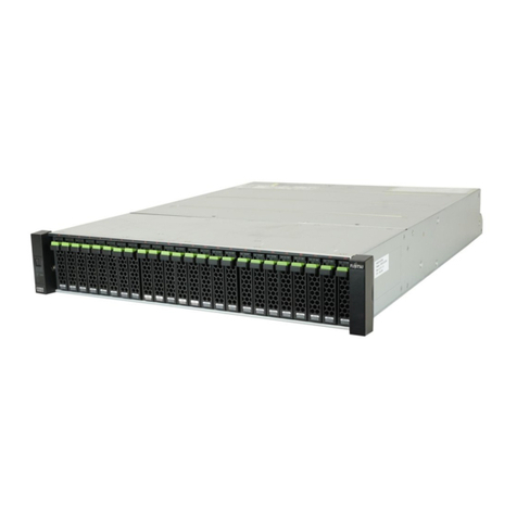
FUJITSU Storage ETERNUS LT270 S2 Tape Library User’s Guide -Panel Operation-
Copyright 2020 FUJITSU LIMITED P3AM-6932-06ENZ0
10
List of Figures
Figure 1.1 Initialization window................................................................................................................................... 14
Figure 1.2 Menu window.............................................................................................................................................. 15
Figure 1.3 Remote panel starting window ................................................................................................................... 16
Figure 1.4 Operator panel (Area configuration) ........................................................................................................... 17
Figure 1.5 Remote panel (Frame layout) ..................................................................................................................... 20
Figure 1.6 Menu layout of the operator panel.............................................................................................................. 21
Figure 1.7 Menu layout of the remote panel................................................................................................................ 22
Figure 2.1 Login window (the [Login] button selected)............................................................................................... 23
Figure 2.2 Login window (password input) .................................................................................................................. 24
Figure 2.3 Selecting the [Information] tab................................................................................................................... 27
Figure 2.4 Reference window for the CAS cell tape cartridge information .................................................................... 28
Figure 2.5 Host interface information reference window (When fabric connection is set)............................................ 30
Figure 2.6 Host interface information reference window (When AL connection and Hard Address are set) ................. 30
Figure 2.7 Host interface information reference window (When AL connection and Soft Address are set)................... 31
Figure 2.8 Library information reference window......................................................................................................... 32
Figure 2.9 Drive information reference window (When the Soft Address is set) ........................................................... 33
Figure 2.10 Drive information reference window (When the Hard Address is set).......................................................... 34
Figure 2.11 Network information reference window (When both IPv4 and IPv6 are enabled) ....................................... 35
Figure 2.12 Network information reference window (When IPv4 is disabled and IPv6 is enabled) ................................ 35
Figure 2.13 Hardware error information display window of the library .......................................................................... 37
Figure 2.14 Hardware error information display window of the drive............................................................................. 38
Figure 2.15 Display of the Alarm button ........................................................................................................................ 38
Figure 2.16 Alarm information display window.............................................................................................................. 39
Figure 2.17 Illumination of the Sign Information button ............................................................................................... 40
Figure 2.18 Information list window .............................................................................................................................. 40
Figure 2.19 Library/drive version information window ................................................................................................... 41
Figure 2.20 Unit information display window ................................................................................................................ 43
Figure 2.21 Selecting the [Setup] tab ............................................................................................................................ 44
Figure 2.22 IPv4 network setup window......................................................................................................................... 45
Figure 2.23 IPv6 network setup window (1/2)................................................................................................................ 46
Figure 2.24 IPv6 network setup window (2/2)................................................................................................................ 47
Figure 2.25 Date and time setting window .................................................................................................................... 48
Figure 2.26 Setup window for screen saver starting time ............................................................................................... 50
Figure 2.27 Password setting window............................................................................................................................ 51
Figure 2.28 Brightness setting window .......................................................................................................................... 52
Figure 2.29 Operation menu window............................................................................................................................. 53
Figure 2.30 Selecting the [CAS Open] button ................................................................................................................. 54
Figure 2.31 Selecting the [Load] button ........................................................................................................................ 56
Figure 2.32 Selecting the [Manual Eject] button............................................................................................................ 57
Figure 2.33 Selecting [Clean] button ............................................................................................................................. 59
Figure 2.34 Selecting [Clean] button ............................................................................................................................. 61
Figure 2.35 Selecting [Clean] button ............................................................................................................................. 62
Figure 2.36 Home window displaying a drive hardware error ........................................................................................ 64
Figure 2.37 Selecting the [Drive Reset] button .............................................................................................................. 65
Figure 2.38 Selecting the [Inventory] button ................................................................................................................. 66
Figure 2.39 Selecting the [Trash Eject] button ............................................................................................................... 67
Figure 2.40 Selecting the [Operator Mode] button ........................................................................................................ 68
Figure 2.41 Selecting the operator mode ....................................................................................................................... 69

