Full Spectrum Laser Muse User manual


Introduction 3
Section I. Safety 4
Fire Safety . . . . . . . . . . . . . . . . . . . . . . . . . . . . . . . . . . . . . . . . . . . . . . . . . . . . . . . . . . . . . . . . . . . . . . . . . . . . . 4
Setup Precautions . . . . . . . . . . . . . . . . . . . . . . . . . . . . . . . . . . . . . . . . . . . . . . . . . . . . . . . . . . . . . . . . . . . . . . . 4
Safety During Operation . . . . . . . . . . . . . . . . . . . . . . . . . . . . . . . . . . . . . . . . . . . . . . . . . . . . . . . . . . . . . . . . . . 5
Electrical Safety . . . . . . . . . . . . . . . . . . . . . . . . . . . . . . . . . . . . . . . . . . . . . . . . . . . . . . . . . . . . . . . . . . . . . . . . . 5
Harmful Materials . . . . . . . . . . . . . . . . . . . . . . . . . . . . . . . . . . . . . . . . . . . . . . . . . . . . . . . . . . . . . . . . . . . . . . . . 6
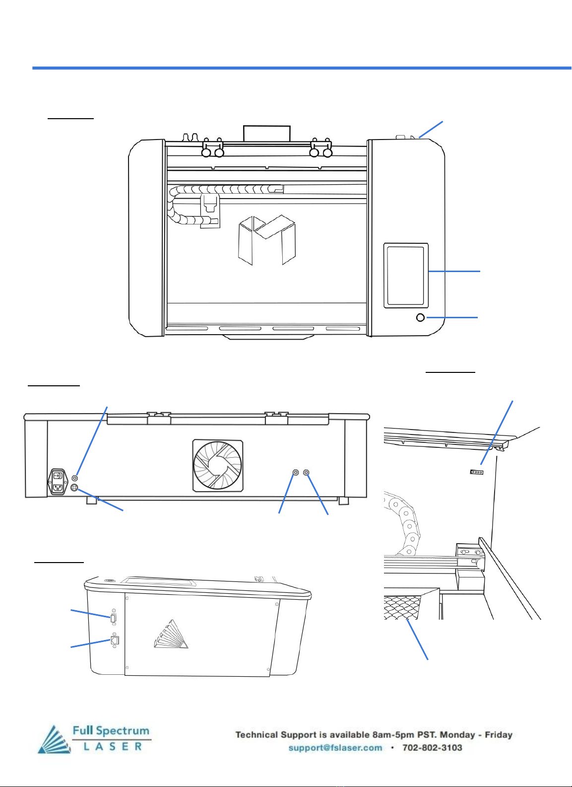
Diagrams . . . . . . . . . . . . . . . . . . . . . . . . . . . . . . . . . . . . . . . . . . . . . . . . . . . . . . . . . . . . . . . . . . . . . . . . . . . . . . . 7
Section Review . . . . . . . . . . . . . . . . . . . . . . . . . . . . . . . . . . . . . . . . . . . . . . . . . . . . . . . . . . . . . . . . . . . . . . . . . . 8
Section II. Unboxing Your Muse Core 9
Unboxing Steps . . . . . . . . . . . . . . . . . . . . . . . . . . . . . . . . . . . . . . . . . . . . . . . . . . . . . . . . . . . . . . . . . . . . . . . . . 9
Checklist . . . . . . . . . . . . . . . . . . . . . . . . . . . . . . . . . . . . . . . . . . . . . . . . . . . . . . . . . . . . . . . . . . . . . . . . . . . . . . 12
Section Review . . . . . . . . . . . . . . . . . . . . . . . . . . . . . . . . . . . . . . . . . . . . . . . . . . . . . . . . . . . . . . . . . . . . . . . . . 13
Section III. Setting Up Your Muse 14
Locate & Remove Zip Ties . . . . . . . . . . . . . . . . . . . . . . . . . . . . . . . . . . . . . . . . . . . . . . . . . . . . . . . . . . . . . . . . . 14
Connect the Exhaust System . . . . . . . . . . . . . . . . . . . . . . . . . . . . . . . . . . . . . . . . . . . . . . . . . . . . . . . . . . . . . . . 15
Preparing Water System . . . . . . . . . . . . . . . . . . . . . . . . . . . . . . . . . . . . . . . . . . . . . . . . . . . . . . . . . . . . . . . . . . 16
Connect the Air Compressor . . . . . . . . . . . . . . . . . . . . . . . . . . . . . . . . . . . . . . . . . . . . . . . . . . . . . . . . . . . . . . . 18
Connect the Electrical Power . . . . . . . . . . . . . . . . . . . . . . . . . . . . . . . . . . . . . . . . . . . . . . . . . . . . . . . . . . . . . . . 19
Section Review . . . . . . . . . . . . . . . . . . . . . . . . . . . . . . . . . . . . . . . . . . . . . . . . . . . . . . . . . . . . . . . . . . . . . . . . . . 20
Section IV. Touchscreen Interface 21
Touchscreen Interface . . . . . . . . . . . . . . . . . . . . . . . . . . . . . . . . . . . . . . . . . . . . . . . . . . . . . . . . . . . . . . . . . . . . 21
Machine Indicator . . . . . . . . . . . . . . . . . . . . . . . . . . . . . . . . . . . . . . . . . . . . . . . . . . . . . . . . . . . . . . . . . . . . . . . . 22
Speed Indicators . . . . . . . . . . . . . . . . . . . . . . . . . . . . . . . . . . . . . . . . . . . . . . . . . . . . . . . . . . . . . . . . . . . . . . . . . 23
Section Review . . . . . . . . . . . . . . . . . . . . . . . . . . . . . . . . . . . . . . . . . . . . . . . . . . . . . . . . . . . . . . . . . . . . . . . . . . 24
Section V. Internet Connection 25
Connect to the Internet . . . . . . . . . . . . . . . . . . . . . . . . . . . . . . . . . . . . . . . . . . . . . . . . . . . . . . . . . . . . . . . . . . . 25
Connect to Software . . . . . . . . . . . . . . . . . . . . . . . . . . . . . . . . . . . . . . . . . . . . . . . . . . . . . . . . . . . . . . . . . . . . . 26
Section Review . . . . . . . . . . . . . . . . . . . . . . . . . . . . . . . . . . . . . . . . . . . . . . . . . . . . . . . . . . . . . . . . . . . . . . . . . 27
Section VI. Tests & Adjustments 28
Alignment Test . . . . . . . . . . . . . . . . . . . . . . . . . . . . . . . . . . . . . . . . . . . . . . . . . . . . . . . . . . . . . . . . . . . . . . . . . . 28
Mirror Alignment . . . . . . . . . . . . . . . . . . . . . . . . . . . . . . . . . . . . . . . . . . . . . . . . . . . . . . . . . . . . . . . . . . . . . . . . 29
Section Review . . . . . . . . . . . . . . . . . . . . . . . . . . . . . . . . . . . . . . . . . . . . . . . . . . . . . . . . . . . . . . . . . . . . . . . . . . 36
Section VII. Focusing Your Laser 37
Focus Procedure . . . . . . . . . . . . . . . . . . . . . . . . . . . . . . . . . . . . . . . . . . . . . . . . . . . . . . . . . . . . . . . . . . . . . . . . . 37
Section Review . . . . . . . . . . . . . . . . . . . . . . . . . . . . . . . . . . . . . . . . . . . . . . . . . . . . . . . . . . . . . . . . . . . . . . . . . . 39
Table of Contents
1

Section VIII. Operations 40
Creating a Design . . . . . . . . . . . . . . . . . . . . . . . . . . . . . . . . . . . . . . . . . . . . . . . . . . . . . . . . . . . . . . . . . . . . . . . . 40
Mouse Control . . . . . . . . . . . . . . . . . . . . . . . . . . . . . . . . . . . . . . . . . . . . . . . . . . . . . . . . . . . . . . . . . . . . . . . . . . 41
Section Review . . . . . . . . . . . . . . . . . . . . . . . . . . . . . . . . . . . . . . . . . . . . . . . . . . . . . . . . . . . . . . . . . . . . . . . . . . 42
Section IX. RetinaEngrave V3 43
Starting on RE3 . . . . . . . . . . . . . . . . . . . . . . . . . . . . . . . . . . . . . . . . . . . . . . . . . . . . . . . . . . . . . . . . . . . . . . . . . . 43
Compound Shapes & Objects . . . . . . . . . . . . . . . . . . . . . . . . . . . . . . . . . . . . . . . . . . . . . . . . . . . . . . . . . . . . . . . 46
Passes . . . . . . . . . . . . . . . . . . . . . . . . . . . . . . . . . . . . . . . . . . . . . . . . . . . . . . . . . . . . . . . . . . . . . . . . . . . . . . . . . 47
Stopping Your Laser . . . . . . . . . . . . . . . . . . . . . . . . . . . . . . . . . . . . . . . . . . . . . . . . . . . . . . . . . . . . . . . . . . . . . . 48
Section Review . . . . . . . . . . . . . . . . . . . . . . . . . . . . . . . . . . . . . . . . . . . . . . . . . . . . . . . . . . . . . . . . . . . . . . . . . . 50
Section X. Maintenance 51
Removing the Laser Tube . . . . . . . . . . . . . . . . . . . . . . . . . . . . . . . . . . . . . . . . . . . . . . . . . . . . . . . . . . . . . . . . . . 51
Setting Up New Tube . . . . . . . . . . . . . . . . . . . . . . . . . . . . . . . . . . . . . . . . . . . . . . . . . . . . . . . . . . . . . . . . . . . . . 53
Belt Replacement . . . . . . . . . . . . . . . . . . . . . . . . . . . . . . . . . . . . . . . . . . . . . . . . . . . . . . . . . . . . . . . . . . . . . . . . 54
Lens & Air Assist Cone Replacement . . . . . . . . . . . . . . . . . . . . . . . . . . . . . . . . . . . . . . . . . . . . . . . . . . . . . . . . . 55
Pass-through . . . . . . . . . . . . . . . . . . . . . . . . . . . . . . . . . . . . . . . . . . . . . . . . . . . . . . . . . . . . . . . . . . . . . . . . . . . . 57
General Maintenance . . . . . . . . . . . . . . . . . . . . . . . . . . . . . . . . . . . . . . . . . . . . . . . . . . . . . . . . . . . . . . . . . . . . . 58
Section Review . . . . . . . . . . . . . . . . . . . . . . . . . . . . . . . . . . . . . . . . . . . . . . . . . . . . . . . . . . . . . . . . . . . . . . . . . . 59
Section XI. Add-ons 60
Coolbox . . . . . . . . . . . . . . . . . . . . . . . . . . . . . . . . . . . . . . . . . . . . . . . . . . . . . . . . . . . . . . . . . . . . . . . . . . . . . . . 60
Warranty 62
Customer Support 63
Table of Contents
2

Thank you for purchasing your new Muse Core. Our high quality products will provide years of service simply by
following proper usage and upkeep. With proper usage and upkeep your machine will be a key part in any design
work.
This user manual will guide you through the safety guidelines and operation of your machine. We recommend that
you familiarize yourself with this manual before using your laser engraver. Remember to be safe and have fun!
For more information and product selection, please visit www.fslaser.com
Introduction
Safety Symbols & Meanings
This icon warns of potential fire hazards and fire risks.
Warning about power surges and electrical risks.
This icon indicates potential eye damage.
Warning about glass or cutting hazards.
This icon warns of potential risks of chemical inhalation.
Important information to keep in mind when running you laser.
3

Laser cutting and engraving systems can present a significant fire hazard due to the extremely
high temperatures generated when the laser beam is in use.
Some material are extremely flammable, catching fire quite easily and damaging the machine and
its surroundings.
Vector cutting has been shown to have the most potential for igniting material due to its direct and steady output
of current. However any function can cause fires due to negligence.
Please read the following warnings and recommendations before using your machine. These instructions should
be followed closely at all times.
●Always keep a properly maintained and inspected 5lbs. or larger fire extinguisher on hand. We
recommend a Halogen or multipurpose dry chemical fire extinguisher.
●Always keep the area around the machine clean and free of clutter. Never stack materials near or in your
work area. Clean the surrounding area regularly to avoid dust getting into the machine.
●Never store any flammable materials in or near the machine.
●Never operate your machine unattended.
●Always use the air assist, especially while vector cutting.
●Never attempt to run a laser with the lid open.
Fire Safety
4
Setup Precautions
Follow all safety protocols and procedures before operating any machinery. It is the responsibility
of the operator to ensure all safety precautions are correctly followed, and that the machine is
properly assembled and in working order.
●Always inspect your machine for damage or breakage before each use. Do not operate machinery
that is damaged or defective in any way.
●Always have a clean, level, and open work space to unbox and place your laser system. Never leave
the laser system unattended during operation.
●Never modify, disassemble, or in any way alter the construction of the laser and never start up a
system that has been modified or disassembled.
●Never operate the machine with any of the panels removed.
●Always have a first-aid kit designed for the initial treatment of burns and smoke inhalation.
●Never place hands or fingers into moving parts such as cooling fans.
Section I. Safety

The output of the CO2 laser is fully contained in a Class 1 enclosure during normal operation. However, the
output beam of the Alignment Laser (visible red diode laser) is accessible to the operator during normal operation, giving
the total system an overall rating of Class 3R. Class 3R lasers have minimal safety concerns when used properly and
handled with care. No special precautions are necessary to operate the high power laser safely. However we recommend
following these Safety Guidelines:
Section I. Safety
5
●Never engrave or cut any unknown material. Never run a laser with the lid open.
●Never operate the machine without a properly operating ventilation system.
●Never look or stare into the visible red diode laser.
Operation Safety
The power supply is capable of releasing a current up to 20mA. This power is sent to the discharge
terminals on the laser tube itself. In order to prevent access to bare wiring your laser shipped with
silicone terminal covers. Please notify Full Spectrum Laser support and immediately cease operations
if the covers ever slips and exposes the bare wires.
Electrical Safety
Note: When performing any replacement procedures, make sure the machine is off for at least an hour.
●Do not open any of the machine’s access panels while the unit is plugged in.
●Never make or break any electrical connections to the system while the unit is turned on. Never
access any electrical areas with hands or tools. The unit should be disconnected from the power for
at least one hour.
●POWER ON/OFF is controlled by the switch at the back of the machine, with (-) being ON and (o)
being OFF.
●Never replace the installed 20 amp fuse with one of a higher rating.
●In case of a blown fuse always contact Technical Support before replacing anything.
Compliance Statement:
The standard for laser safety is the American Standard for the Safe Use of Lasers, Z136.12000. Developed by the American National Standards
Institute (ANSI) it is the basis for many federal regulations and Occupational Safety and Health Administration (OSHA) guidelines for laser and
laser system manufacturers. It contains detailed information concerning the proper installation and use of laser systems. While the ANSI
standard is not a law, its recommendations, including warning signage, training, and the designation of a laser safety officer, may be mandatory
under local regulations. It is the operator's responsibility to ensure that the installation and operation of the Full Spectrum Desktop Laser System
are performed following applicable laws. Copies of ANSI Standard Z136.12000 are available from:
LASER INSTITUTE OF AMERICA 12424 RESEARCH PARKWAY, SUITE 125 ORLANDO, FL 32826 (407) 3801553.

Material DANGER! Issues
PVC (Poly Vinyl Chloride)/Vinyl/
Pleather/Most Artificial Leather
Emits Chlorine gas fumes This material can ruin the optics as well as cause the metal of the
machine to corrode. PVC can also ruin the motor system.
Thick ( >1mm )
Polycarbonate/Lexan
Catches fire Polycarbonate is used in the window of varies laser cutters
because it absorbs infrared radiation. Therefore, it cannot be cut
with laser engravers. Trying to do so will create soot that can ruin
the optics and mess up the machine.
ABS plastic Melts, Emits Cyanide
fumes
ABS tends to melt creating melted deposits in the workspace and
is subsequently a high fire risk. It can also release lethal amounts
of hydrogen cyanide.
HDPE/Milk Bottle Plastic Catches fire and melts HDPE can melt creating melted deposits in the workspace and is
subsequently a high fire risk.
PolyStyrene Foam Catches fire Foam can ignite quickly and spread flames rapidly.
PolyPropylene Foam Catches fire Foam can ignite quickly and spread flames rapidly.
Epoxy Emits fumes Epoxy is a resin made out of carbon. Therefore, a CO2 laser can't
cut it. Attempting to do so will result in toxic fumes.
Fiberglass Emits fumes It is made of glass and epoxy. Do not attempt.(Refer to epoxy)
Coated Carbon Fiber Emits fumes Cannot be cut and will emit toxic fumes.(Refer epoxy)
Any food Toxicity Our machines are not designed to be used with food as they
possess no safe food contact surfaces. There are also risks
involved with debris in the workspace polluting any food placed in
the interior. Do not put food in or around the machine.
Material with Sticky Glue or
Adhesive Backing
Coats lens or cracks lens Items that can normally be cut become uncuttable when the
manufacturer adds a layer of peel-off glue on the bottom to
attach them to surfaces.The glue will vaporize forming a coating
on the lens that will coat, cloud, heat, and potentially crack the
lens. It can't be removed without damaging to the lens, requiring a
lens replacement.
DO NOT CUT MATERIALS THAT HAVE THIS BACKING!
HARMFUL MATERIALS:
WARNING!! TRYING TO CUT THESE ITEMS WILL VOID WARRANTY!!
CUT AT YOUR OWN RISK!
6
Section I. Safety

The following diagrams will help you locate all of the machines components.
Section I. Safety
7
Top View:
Side View:
Back View:
Side View:
Power Switch
Play/ Pause
Button
Exhaust
Water
In/out
Touchscreen
Power Switch Water
In
Water
Out
Air Inlet
Machine
Control
Ethernet
Port
USB Port
Rotary Port
Honeycomb Tray

Section Review:
Do’s:
●Remember to make sure your work area is nice an clean. Keep your laser system clean.
●Always keep an eye on your machine.
●Always inspect your machine for damage or breakage before each use.
●Always keep a fire extinguisher and a first-aid kit (preferably one designed for the initial
treatment of burns and smoke inhalation) on hand.
Don’ts:
●Do Not stack items on or near your work area.
●Do Not leave your machine unattended.
●Never operate the machine with any of the panels removed or without a properly operating
ventilation system.
●Never access any electrical areas with hands or tools unless the unit is disconnected from
the power for at least one hour.
●Never place hands or fingers into moving parts such as cooling fans.
Section I. Safety
8

Section II. Unboxing
The Muse Core has a weight of 54 lbs. To avoid the potential of injury, two people are needed to lift
and unbox the machine. Lift At Your Own Risk.
Unboxing Steps
Follow these instructions for best results:
1. Prepare Work Space: You will need an open, level work space to place your laser cutter. A sturdy table with
room for the machine ( 32.5”x 20.3”x 8.5” for the workspace) is recommended. Be sure the table is free of
clutter and can support a minimum of 200lbs (the machine itself weighs 54 lbs).
2. Place Box: Place your box on or near your table before opening it, using either a pair of scissors or a box cutter.
13.7”
36.7”
25.55”
9

Section II. Unboxing
3. Open the box. Carefully remove the Honeycomb tray.
4. Remove the foam layer to access the machine.
10
5. Two people should carefully remove the Muse Core
from the box.

Section II. Unboxing
6. Inspect the outside of your machine.
7. Open the Muse and remove the Coolbox package.
11
8. Remove the Accessory box.
9. Remove the Foam from under the Gantry.
10. Remove the Foam from under the side panels.

Checklist
Your laser should come with the following included parts and accessories:
● Never use unapproved ducting in the exhaust system as it is potentially
flammable.
●Never operate your laser without a working exhaust. Full Spectrum Laser
recommends exhaust systems capable of AT LEAST 500CFM. Keep in mind that
exhaust systems with high flow rates may require a particle filter for materials with
significant particulates such as wood.
Additional Items
You will also need the following tools(not included in your purchase):
1 gallon of
distilled water
Small Scissors
Section II. Unboxing
12

Section II. Unboxing
13
Section Review:
Do’s:
●Remember to Lift Your Box with a partner. Remember to lift with your knees.
●Check your 3D for any damage prior to use.
●Make sure to check that your machine came with all the items on the checklist.
Don’ts:
●Do Not lift the box alone. Do Not lift using your waist, back or arms as it can lead to injury.
●Do Not use your machine if you see any damage. Contact Support immediately.

This assembly is a simple process that should take less than half an hour to complete. For simplicity we divided the
assembly into five easy steps.
1. Locate & Remove Zip Ties
2. Connect the Exhaust System
3. Assemble the Water System(Hobby Kit)
4. Assemble the Air Compressor(Hobby Kit)
5. Connect Electrical Power
Fig. 1
Or
Section III. Setting Up Your Muse
Please note: Zip Ties may vary in color. Refer to the provided pictures on which zip ties are cuttable.
WARNING!! Do not cut zip ties holding other wires unless instructed to do so by support. Do not cut belts by accident.
1. Locating & Removing Zip Ties
The machine was secured during shipping with zip ties to hold the laser head assembly and the x-gantry. Remove zip ties
before operating your laser cutter for the first time.
14

2. Connecting the Exhaust System
An exhaust fan is required to be connected and on whenever a job is run on your laser. A properly installed exhaust fan
removes smoke and fumes from the case and exhausts them to the outside of the building or a fume extractor.
1. Install Exhaust Flange: Use the provided flange bolts to install the ducting collar on the rear of the machine as
shown in Fig. 3.
Fig. 2 Fig. 3
2. Position Ducting: Place your 4” ducting over the Exhaust Port located at the back of the machine and hold.
Secure with 4” ducting clamp. (See Fig. 3)
Fig. 4
3. Attach Exhaust Fan: Secure the free end of the ducting to the exhaust fan. Repeat the ducting and clamping
process in the other side of the exhaust fan and plug in the fan into the bottom power plug marked “exhaust”
on the back of your Muse Core machine. (see Fig. 4).
4. Ventilate Outside or to Fume Extractor: Set the open end outside of a window or to a fume extractor. Check
your system for leaks and be aware that the protective housing is not designed to be airtight; the front grill is
designed to allow an exhaust system to draw fresh air though the work area.
5. Connect to Power: Plug the power cord from the exhaust fan power into the plug marked “exhaust fan” on the
back of your Muse Core.
Note: Accessories plugged into the back of your 3D will only turn on when the laser is fired (as intended).
FROM MUSE
TO OUTSIDE VENTILATION/
FUME EXTRACTOR
Section III. Setting Up Your Muse
15

Section III. Setting Up Your Muse
3. Water System Assembly
The Muse Core comes with an optional Hobby Kit that contains both the Air Compressor and Water Pump. If the
Coolbox option was selected instead, then proceed to the “Add-on” section on pg 62.
Muse Core uses a water-cooled continuous beam CO2 laser tube. The tube requires a flow of room temperature
water to help regulate the temperature of the laser tube. Your purchase includes a water chiller for cooling the
laser tube.
Never Fire the Laser without a correctly connected and powered water chiller. Firing the
laser without turning the pump on or with no water in the system will severely degrade or
destroy your laser tube and void your warranty.
2. Attach Water Pump Fitting: Remove the water pump from its packaging. Attach the plastic fitting to the
water pump and screw on.
1. Remove Water Cap: Remove the short silicone tubing, capping the water inlet and outlet on the back
off the machine.
Fig. 6
Fig. 5
Fig. 7
16

NOTIC ●We recommend that you attach the laser and water pump to a power strip and use that to
control the main power to the unit, ensuring that the water pump is always on when the
laser is powered.
●Make sure that there are no air bubbles inside of the water jacket of the laser tube as it
can reduce the lifetime of your tube. If present, water bubbles typically migrate to the
electrodes on either end of the tube. Visually inspect the laser tube to make sure that
bubbles are not present. If bubbles persists completely drain the tube of water then turn
the chiller back on and check once more.
NOTICE!
3. Prepare the Water Bucket: Fill a 5 gallon bucket(not included) by about 2/3rd using distilled water.
Make sure to only use distilled water and replace often. If you live in a cold climate you can use a 1:2
Propylene Glycol and Distilled water mix to prevent freezing. Generally Muse Titan systems should not be
run in temperatures less than 20°F (-6°C).
Note: We recommend a bucket with a lid be used to prevent debris from falling in. Make holes for
tubing if needed.
4. Attaching the Water Outlet Tubing: Connect one end of a water tube to the Water Out tube on the
back of your machine. Place the other end of the tubing into the bucket of water.
5. Attaching the Water Inlet Tubing: Connect the second tube to the Water In tube and place the
other end on the plastic filling on the pump.
6. Place the water pump into the bucket and plug in for use.
Fig. 9
Fig. 8
Section III. Setting Up Your Muse
17

4. Connect the Air Compressor
Air is used as a pressurized gas to assist in cutting and engraving operations. This pressurized air is critical to safe and
efficient cutting operations as it not only helps cut through material more quickly, but also helps prevent the formation
of flames.
3. Connect to Power: Plug the air compressor power cord into the marked “Air Assist” on the back of your 3D.
1. Tubeing: Remove the air compressor from its packaging and attach the silicone tube on the air compressor.
2. Attach Air Hose to Laser Cutter: Insert the other end of the hose into the “air inlet” nozzle in the back of the
laser cutter through the barbed air connect.
Fig. 10
Fig. 11
Section III. Setting Up Your Muse
18

The Muse Core and its accessories are configured to accept 110VAC at 60Hz. For international purposes we offer an
optional single-phase 220VAC converter.
1. Prepare Power Cord: Remove the electrical cord from its packaging.
2. Plug in Power Cord To Laser Cutter: The power cord plugs into the C14 slot located on the back of the machine.
Ensure the red power switch is turned on.
3. Plug in Power Cord to Outlet: Plug the power cord into any proper outlet socket in your workspace.
NOTICE!
Section III. Setting Up Your Muse
●Please be aware that the accessories will increase circuit load
The most significant power draw usually comes from the blower/exhaust
system. Consult the manufacturer’s information and manual for the operating
parameters of your exhaust system.
●The power inlet is equipped with a fuse to protect the machine from surges or
short circuits in case of emergencies. If this fuse ever needs replacement,
please contact Full Spectrum Laser technical support.
Fig. 12
AIR
EXHAUST
MAIN POWER
CORD
C-14 POWER
RECEPTACLE
AIR
COMPRESSOR
OUTLET
19
Other manuals for Muse
6
This manual suits for next models
1
Table of contents
Other Full Spectrum Laser 3D Printer manuals