1. Important safety instructions
WARNING
Before installing and using the charger, read all instructions and
cautionary marking on the charger, the batteries and all
appropriate sections of this guide.
General safety precautions
Do not expose the charger to rain, snow, spray, or bilge water. To reduce risk of fire hazards,
do not cover or obstruct the ventilation openings. Do not install the inverter in a zero-
clearance compartment. Overheating may result.
The charger is designed to be permanently connected to your AC and DC electrical systems.
Never use chagers at a location where there is a danger of gas or dust explosions.
Use only attachments recommended or sold by the manufacturer. Doing otherwise may result
in a risk of fire, electric shock or injury to persons.
Do not disassemble the charger. Attempting to service the unit yourself may result in a risk of
electric shcok of fire. Internal capacitors remain charged after all power is disconnected.
The charger must be provided with an equipment-grounding conductor connected to the AC
input groung.
To reduce the risk of electrical shock, disconnect both AC and DC power from the charger
before attempting any maintenance or cleaning or working on any circuits connected to the
charger. Turning off controls will not reduce this risk.
Do not operate the charger if it has received a sharp blow, been dropped, or otherwise
damaged in any.
To avoid a risk of fire and electric shock make sure that existing wiring is in good electrical
conditions and the wire size is not undersized. Do not operate the inverter with damage or
substandard wiring.
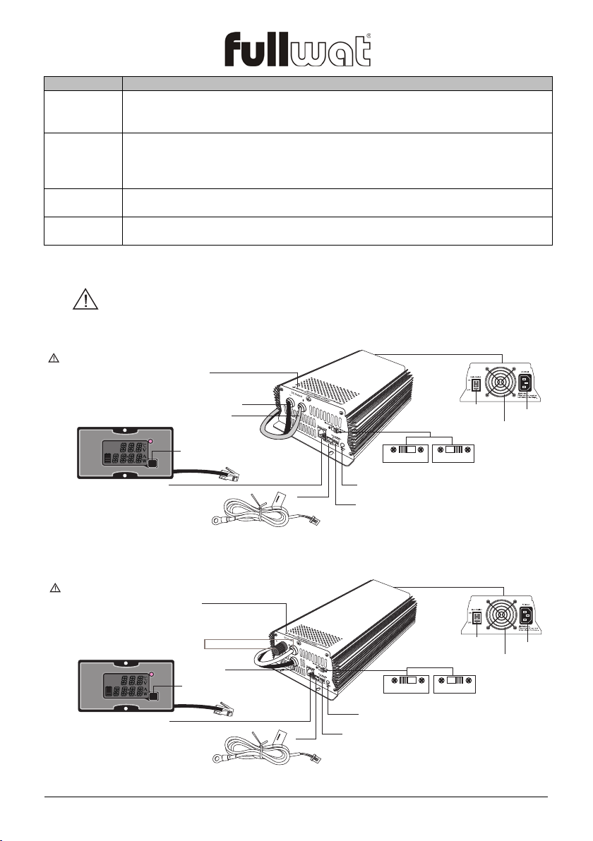
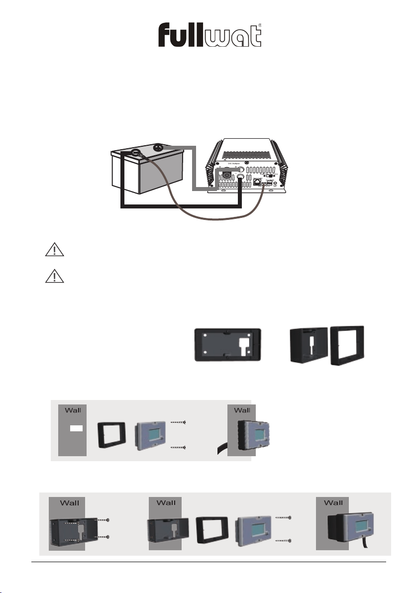
2. Installation location; physical requirements for installation
IMPORTANT
This product is best mounted in a horintal position. If unit is mounted in a vertical position the
cooling fan must be at botton of the unit.
Do not expose the charger to metal filings or any other form of conductive contamination.
The presence of conductive contamination can cause damage and void your warranty.
For best performance, the ambient air temperature should be between -15°C (5°F) and
45°C (113°F) – the cooler the better. At higher ambient temperatures, the output current
will be automatically reduced to protect the charger from high internal temperatures.
The unit is intended for use in a dry location. Do not allow water or other fluids to drip or
splash on the charger. Do not mount the charger in an area subject to rain, spray or
User’s manual - 1 - FUM-12xxCBPH/24xxCBPH