NZ eSTOP™ Operations & Service Manual
Page | 6
Fulton Hogan Signs & Graphics |signs@fultonhogan.com | P: 0800 274 463
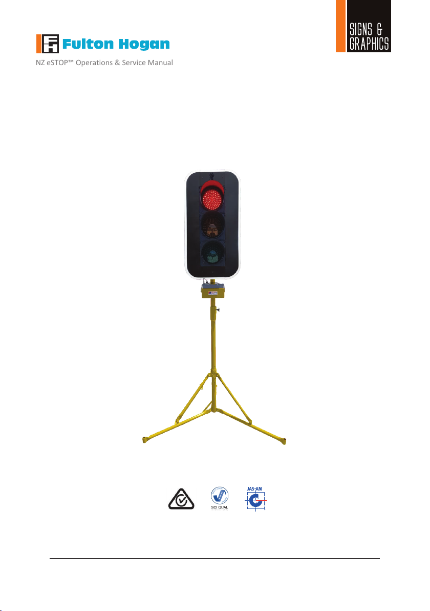
The eSTOP™has beendeveloped as a response to aneed for safer working conditions foroperators
controlling alternating flow situations on job sites. It is designed to remove operators from the hazard
zones, butstill allowing the operators to manage traffic movement within the worksite from a safe
distance. In order to reduce the risk to road workers, traffic controllers and road users, the unit must at
all times be operated effectively and consistently by authorized and trained operators.
The eSTOP™must be operated in accordance with all safety, operation and service instructions contained
in the manufacturer's operation and service manual. It is recommended that all operators read and
understand the manual before operating the eSTOP™. Operators must understand and comply with the
manufacturer's instructions as printed in the manual accompanying each eSTOP™in conjunction with the
respective Company’s (User’s) Safe Work Method Statement.
The eSTOP™should only be operated by a designated, competent operator within the scope of on-site
operation parameters (such as the Company’s Safe Work Method Statement).
The eSTOP™shall be installed in a suitable location clear of obstructions. An appropriate risk assessment
shall be conducted to ensure the safe and suitable use of the eSTOP™. Examples of factors to consider
when assessing suitable location are: a safe distance from the traffic path, so that wide loads or turning
vehicles will not impact the unit, length of worksite, volume of traffic and topography. The eSTOP™should
be installed on a stable surface.
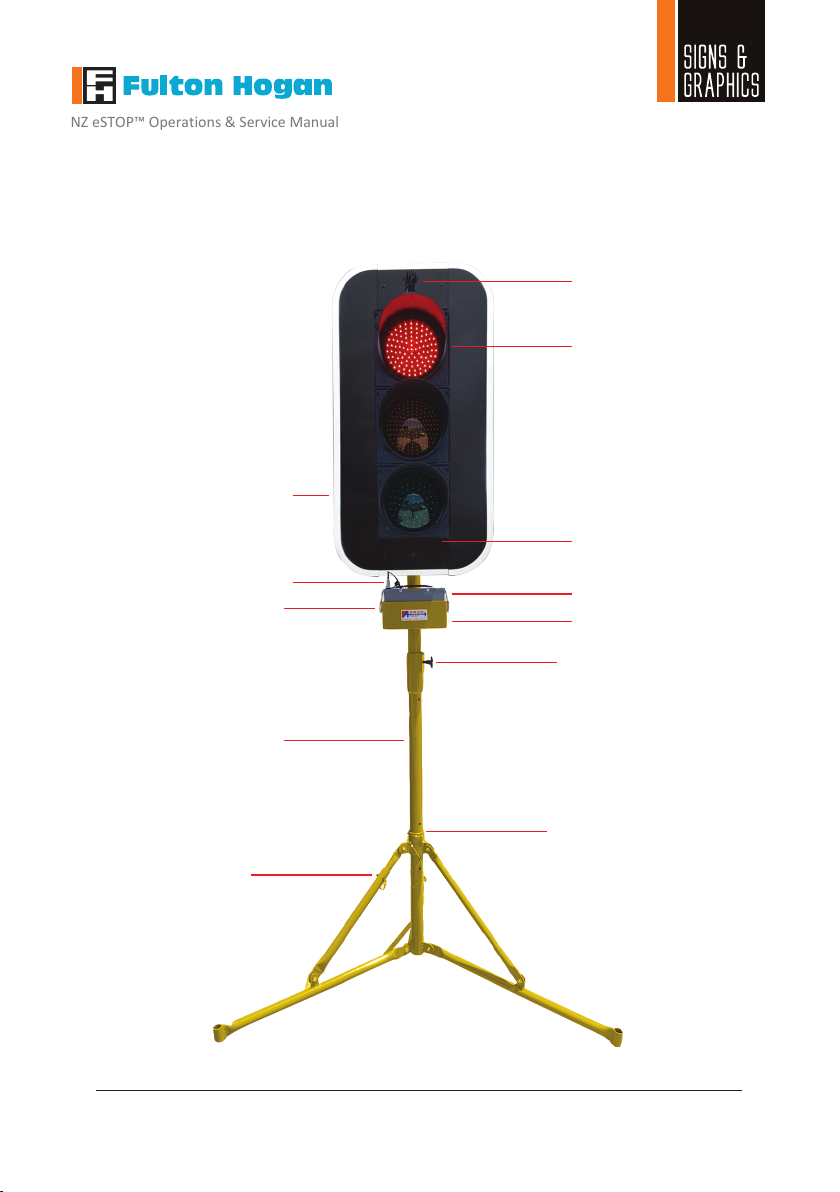
The unit including the lanterns (red, yellow and green), yellow light indicator and battery box shall be kept
clean. The equipment shall be handled with care.
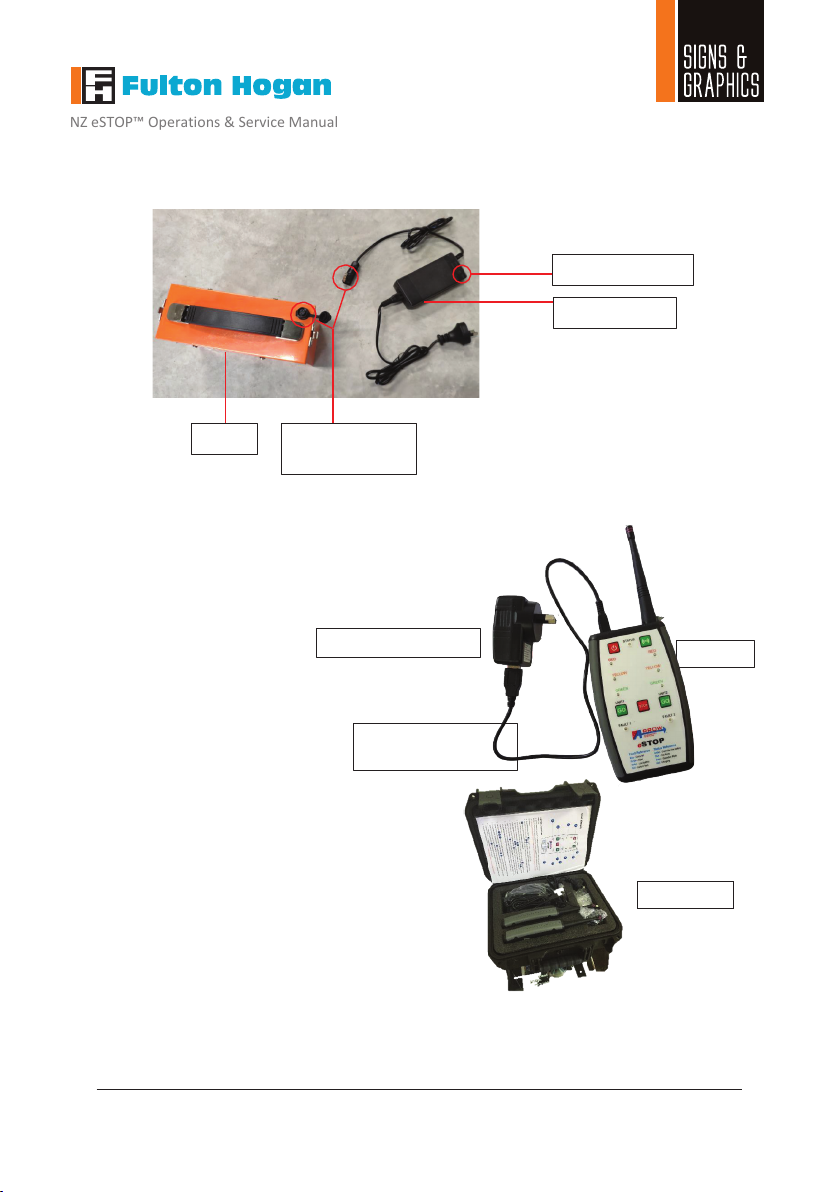
The eSTOP™batteries (both for the hand remote control and the lanterns) shall be fully charged before
operating the unit.
The eSTOP™has been tested and certified compliant in accordance with the New Zealand Transport
Agency (NZTA) Technical Note –Portable Traffic Signal Systems, Version 3 : November 2015. The
eSTOP™ is included in the NZTA Code of Practice for Temporary Traffic Management (CoPTTM) Register
of TTM equipment approved for use on NZ roading network (Section I-19). The application of the
eSTOP™shallbe in accordance to these guidelines/standards as well as the respective company’s
worksite risk assessment and approved Traffic Management Plan (TMP).
It should be noted: the eSTOP is a remote control MANUAL operated system, designed to
remove operators from exposure to LIVE traffic. The maximum distance from the HRC and therefore the
operator to the lantern heads is 400m. However, the site distance which the eSTOP can be deployed
varies from site to site and must be deployed in accordance to the worksite risk assessment and
therefore must be set up in accordance to the respective site Traffic Management Plans.
Any modifications madeto the eSTOP™(unless byor approved by ArrowES) could compromise the function
of the eSTOP™and therefore the safe application of the units and voids the warranty of the eSTOP™.
Fulton Hogan Signs & Graphics |signs@fultonhogan.com | P: 0800 274 463
™
eSTOP™ Unit
Operating life of cluster: 100,000 hours
View angel of cluster: 12⁰
Lantern IP rating: IP45
LED Optics IP rating:IP65
Voltage: 12v
Operating amperage: 1.2 A
Battery (rechargeable) 26 A/H Lithium Iron phosphate
Operating Hours (80% DoD) ~16 Hours
Charging time: 4-5 Hours
Operating Temperature Range: -20 to 90⁰Celsius
Lantern Compliancy AS2144
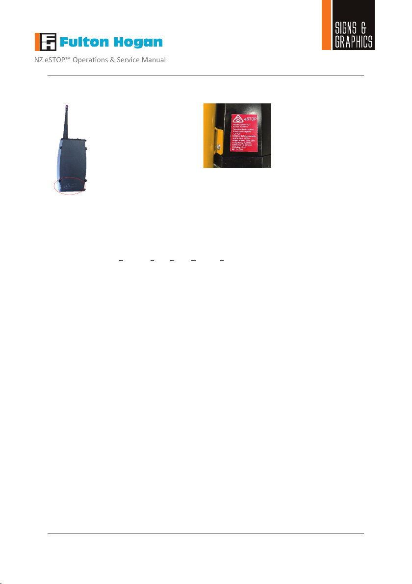
Hand Remote Controller (HRC)
RF operating frequency: 2.4GHz
Configuration: Single unit or dual unit control
IP rating:IP65
Battery (rechargeable): 3 A/H Lithium Polymer
Operating Hours (50% DoD) ~15 Hours
Charging time: 4-6 Hours
Operating Current: (Transmitting) 120mA
Sleeping Current: 1mA
Operating Temperature Range: -20 to 85⁰Celsius
OverallDevice
Total mass per device (incl. batt,Target Board): 24kg (allocated to 3 components)
Top lantern weight (max lifting weight): 14kg
Tripod leg footprintradius: 0.80m
Wind loading–no sandbag base: ~40km/h
Wind loading–3 sandbag/leg ~50kg: ~100km/h
Dimensions
Maximum working height: 2900 cm
Minimum working height: 2600 cm
Dimensions when stored: 1710 mm x 480mm x 370mm
Base width, fully extended: 1600 mm diameter
Lantern height: 770 mm
Lantern width: 270 mm
Lantern depth: 170 mm
Target Board: 562x1063mm