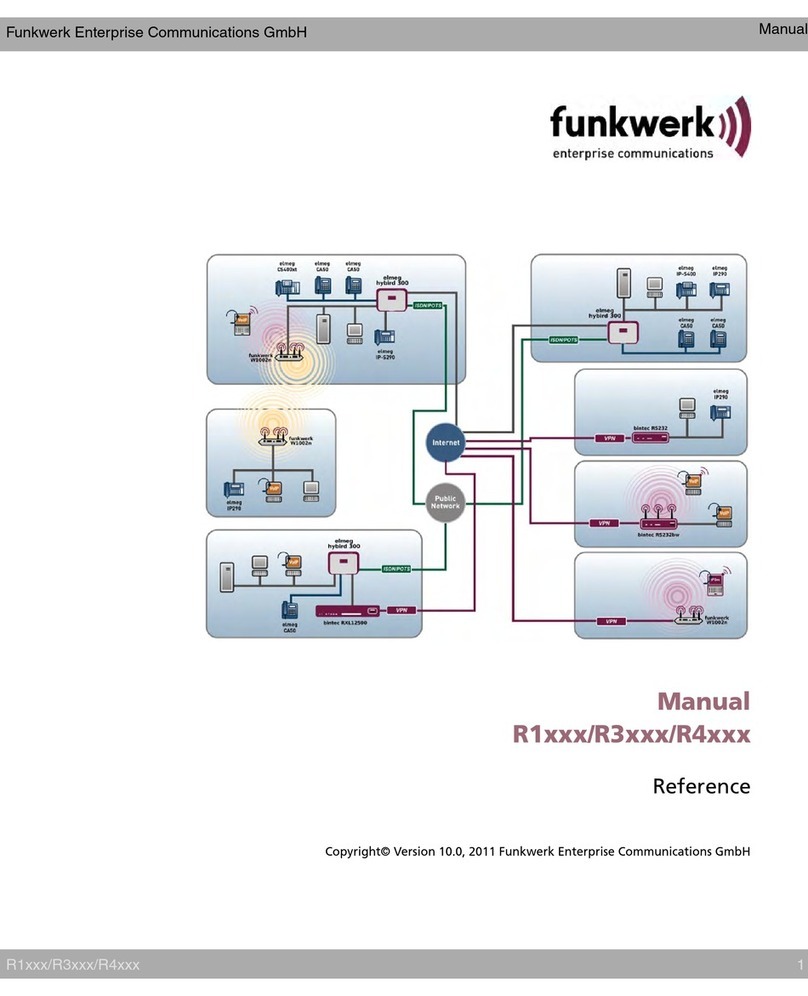
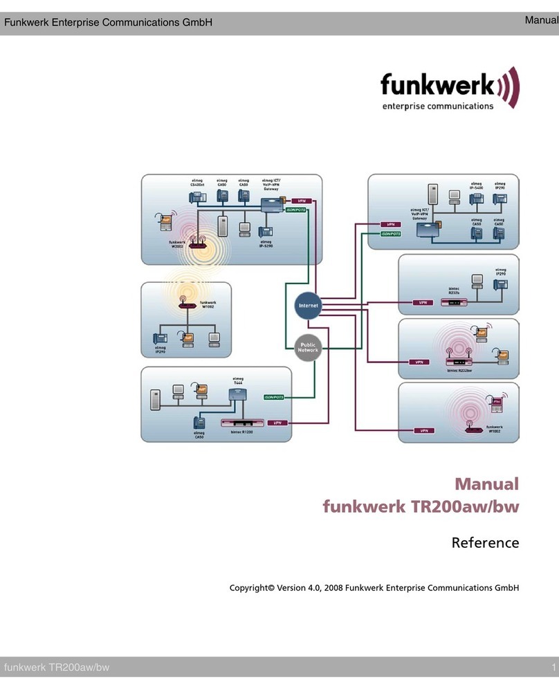
Funkwerk bintec R230aw User manual

Copyright ©April 26, 2006 Funkwerk Enterprise Communications GmbH
Version 2.0
User’s Guide
bintec R230a / R230aw / R232b / R232bw
System

Purpose This document is part of the user’s guide to the installation and configuration of bintec gateways run-
ning software release 7.2.10 or later. For up-to-the-minute information and instructions concerning the
latest software release, you should always read our Release Notes, especially when carrying out a
software update to a later release level. The latest Release Notes can be found at www.funkwerk-
ec.com.
Liability While every effort has been made to ensure the accuracy of all information in this manual, Funkwerk
Enterprise Communications GmbH cannot assume liability to any party for any loss or damage caused
by errors or omissions or by statements of any kind in this document and is only liable within the scope
of its terms of sale and delivery.
The information in this manual is subject to change without notice. Additional information, changes and
Release Notes for bintec gateways can be found at www.funkwerk-ec.com.
As multiprotocol gateways, bintec gateways set up WAN connections in accordance with the system
configuration. To prevent unintentional charges accumulating, the operation of the product should be
carefully monitored. Funkwerk Enterprise Communications GmbH accepts no liability for loss of data,
unintentional connection costs and damages resulting from unsupervised operation of the product.
Trademarks bintec and the bintec logo are registered trademarks of Funkwerk Enterprise Communications GmbH.
Other product names and trademarks mentioned are usually the property of the respective companies
and manufacturers.
Copyright All rights are reserved. No part of this publication may be reproduced or transmitted in any form or by
any means – graphic, electronic, or mechanical – including photocopying, recording in any medium,
taping, or storage in information retrieval systems, without the prior written permission of Funkwerk En-
terprise Communications GmbH. Adaptation and especially translation of the document is inadmissible
without the prior consent of Funkwerk Enterprise Communications GmbH.
Guidelines and standards bintec gateways comply with the following guidelines and standards:
R&TTE Directive 1999/5/EG
CE marking for all EU countries and Switzerland
You will find detailed information in the Declarations of Conformity at www.funkwerk-ec.com.
How to reach Funkwerk
Enterprise Communications
GmbH
Funkwerk Enterprise Communications GmbH
Suedwestpark 94
D-90449 Nuremberg
Germany
Telephone: +49 180 300 9191 0
Fax: +49 180 300 9193 0
Internet: www.funkwerk-ec.com
Bintec France
6/8 Avenue de la Grande Lande
F-33174 Gradignan
France
Telephone: +33 5 57 35 63 00
Fax: +33 5 56 89 14 05
Internet: www.bintec.fr
System bintec User’s Guide 1
1System Menu . . . . . . . . . . . . . . . . . . . . . . . . . . . . . . . . . . . . . . . . . . . 3
2Submenu
External Activity Monitor . . . . . . . . . . . . . . . . . . . . . . . . . . . . . . . . . 7
3Submenu
External System Logging . . . . . . . . . . . . . . . . . . . . . . . . . . . . . . . . . 9
4Submenu Schedule & Monitor . . . . . . . . . . . . . . . . . . . . . . . . . . . . 13
4.1 Submenu Keepalive Monitoring
(Hosts & Ifc) . . . . . . . . . . . . . . . . . . . . . . . . . . . . . . . . . . . . . . . . . . . . . . . 13
4.2 Submenu Event Scheduler
(Time & SNMP) . . . . . . . . . . . . . . . . . . . . . . . . . . . . . . . . . . . . . . . . . . . . 18
4.2.1 Configuration of triggers (Events) . . . . . . . . . . . . . . . . . . . . . . . . 19
4.2.2 Configuration of the Action (Command) . . . . . . . . . . . . . . . . . . . 26
5Submenu Password Settings . . . . . . . . . . . . . . . . . . . . . . . . . . . . . 33
6Submenu Time and Date . . . . . . . . . . . . . . . . . . . . . . . . . . . . . . . . . 35
Index: System . . . . . . . . . . . . . . . . . . . . . . . . . . . . . . . . . . . . . . . . . 39

2 bintec User’s Guide System

System bintec User’s Guide 3
System Menu 1
1 System Menu
The fields of the SYSTEM menu are described below.
The SYSTEM menu is used for e.g. entering the basic system data of your gate-
way.
The SYSTEM menu consists of the following fields:
R232bw Setup Tool Funkwerk Enterprise Communications GmbH
[SYSTEM]: Change System Parameters MyGateway
System Name r232bw
Local PPP ID (default) r232bw
Location
Contact BINTEC
Syslog Output on Serial Sonsole no
Message Level for the Syslog Table info
Maximum Number of Syslog Entries 20
Maximum Number of Acctlog Entries 20
External Activity Monitor >
External System Logging >
Schedule & Monitor >
Password Settings >
Time and Date >
SAVE CANCEL
Field Description
System Name Defines the system name of your gateway; is
also used as PPP host name. Appears as input
prompt when logging in to the device.
The device type is entered as default value.
Local PPP ID (default) This entry is necessary to identify your gateway
if the remote gateway requests the PPP ID
before the gateway has identified itself to the
remote terminal.
The device type is entered as default value.

1
4 bintec User’s Guide System
System Menu
Location Indicates where your gateway is located.
Is shown, for example, on the HTML system
information page or in the login message.
Contact Indicates the responsible contact person. Here
you can enter the e-mail address of the system
administrator, for example.
Default value: BINTEC.
Is shown, for example, on the HTML system
information page.
Syslog Output on Serial
Console
Enables the display of syslog messages on the
PC connected to the serial interface of the
gateway. Use this setting only if you make a
fault analysis, as a very large output over the
serial console adversely affects the throughput
of the other interfaces.
You should normally use EXTERNAL SYSTEM
LOGGING. Possible values:
■yes
■no (default value)
Field Description

System bintec User’s Guide 5
System Menu 1
Table 1-1: SYSTEM menu fields
Message Level for the
Syslog Table
Specifies the priority of the syslog messages to
be recorded internally. Possible values:
■emerg: emergency messages (highest pri-
ority)
■alert: alert messages
■crit: critical messages
■err: error messages
■warning: warning messages
■notice: notice messages
■info (default value): info messages
■debug: debug messages (lowest priority)
Syslog messages are only recorded internally if
they have a higher or identical priority to that
indicated, i.e. all messages generated are
recorded at syslog level debug.
Maximum Number of Sys-
log Entries
Maximum number of syslog messages saved
internally in the gateway (possible values: 0...
1000).
Default value: 20.
You can show the saved messages in the
Setup Tool under MONITORING AND DEBUGGING
➜MESSAGES.
Maximum Number of
Acctlog Entries
Maximum number of accounting messages
saved internally in the gateway (possible val-
ues: 0... 1000).
Default value: 20.
Field Description

1
6 bintec User’s Guide System
System Menu

System bintec User’s Guide 7
Submenu External Activity Monitor 2
2 Submenu
External Activity Monitor
The fields of the EXTERNAL ACTIVITY MONITOR submenu are described below.
The SYSTEM ➜EXTERNAL ACTIVITY MONITOR menu contains the settings neces-
sary for monitoring your gateway with the Windows Activity Monitor tool (part of
BRICKware for Windows).
Purpose The Activity Monitor enables Windows users to monitor the activities of the
gateway. Important information about the status of physical interfaces (e.g.
ISDN line) and virtual interfaces (e.g. WAN partner) is easily obtained with one
tool. A permanent overview of the utilization of the gateway is possible.
Method of operation A Status Daemon collects information about the gateway and transfers it in the
form of UDP packets to the broadcast address of the first LAN interface (default
setting) or to an explicitly entered IP address. One packet is sent per time inter-
val, which can be adjusted individually to values from 1 - 60 seconds. Up to 100
physical and virtual interfaces can be monitored, provided the packet size of
4,096 bytes is not exceeded. The Activity Monitor on your PC receives the pack-
ets and can display the information contained in them in various ways according
to configuration.
Activate the Activity Monitor as follows:
■Configure the relevant gateway(s) to be monitored.
R232bw Setup Tool Funkwerk Enterprise Communications GmbH
[SYSTEM]: [ACTIVMON]: External Activity Monitor MyGateway
Client IP Address 255.255.255.255
Client UDP Port 2107
Type off
Update Interval (sec) 5
SAVE CANCEL

2
8 bintec User’s Guide System
Submenu External Activity Monitor
■Start and configure the Windows application on your PC (see BRICKware
for Windows).
The EXTERNAL ACTIVITY MONITOR menu consists of the following fields:
Table 2-1: EXTERNAL ACTIVITY MONITOR menu fields
Field Description
Client IP Address IP address to which the gateway sends the
UDP packets.
The default value 255.255.255.255 means that
the broadcast address of the first LAN interface
is used.
Client UDP Port Port number for the bintec Activity Monitor
(default value: 2107, registered by IANA - Inter-
net Assigned Numbers Authority).
Type Type of information sent in the UDP packets to
the Windows application. Possible values:
■off: Deactivates the Activity Monitor (de-
fault value)
■physical: Only information about physical
interfaces
■physical_virt: Information about physical
and virtual interfaces
Update Interval (sec) Update interval in seconds. Possible values: 0
to 60 (default value: 5).
The value 0deactivates the function.

System bintec User’s Guide 9
Submenu External System Logging 3
3 Submenu
External System Logging
The fields of the EXTERNAL SYSTEM LOGGING submenu are described below.
The SYSTEM ➜EXTERNAL SYSTEM LOGGING menu shows the log host settings.
Events in the various subsystems of the gateway (e.g. ➤➤ PPP) are logged in
the form of syslog messages (system logging messages), see “System Menu”
on page 3. The number of messages visible depends on the level set (eight
steps from emerg and info to debug).
In addition to the data logged internally on the gateway, all information can and
should also be passed to one or more external PCs for storage and processing,
e.g. to the system administrator’s PC. The syslog messages saved internally on
the gateway are lost on a restart.
Syslog Daemon All Unix operating systems support the recording of syslog messages. For Win-
dows PCs, the Syslog Daemon included in the DIME Tools can record the data
and distribute to various files depending on the contents (see BRICKware for
Windows).
R232bw Setup Tool Funkwerk Enterprise Communications GmbH
[SYSTEM][LOGGING][ADD] MyGateway
Log Host
Level info
Facility local0
Type all
Timestamp none
Method udp
SAVE CANCEL
Warning!
Make sure you only pass syslog messages to a safe computer. Check the data
regularly and ensure that there is always enough spare capacity available on the
hard disk of your PC.

3
10 bintec User’s Guide System
Submenu External System Logging
The settings for saving syslog messages externally are made in SYSTEM ➜
EXTERNAL SYSTEM LOGGING ➜ ADD/EDIT.
The menu consists of the following fields:
Field Description
Log Host ➤➤IP address of the host to which syslog
messages are passed.
Level Priority of the syslog messages to be sent to
LOG HOST. The possible values correspond to
those in “Message Level for the Syslog Table”
on page 5.
Only syslog messages with the same or higher
priority than indicated are passed to the LOG
HOST, i.e. all the messages created are passed
to the LOG HOST in syslog LEVEL Debug.
Facility Syslog facility at LOG HOST. Only required if the
LOG HOST is a Unix computer.
Possible values: local0 - 7 (default value
local0).
Type Message type. Possible values:
■all: All messages (default value)
■system: Syslog messages except
➤➤ accounting messages.
■accounting: Accounting messages
Timestamp Format of the system time of the R Series gate-
way in the syslog. Possible values:
■all: System time with date
■time: System time without date
■none: No system time shown (default value)

System bintec User’s Guide 11
Submenu External System Logging 3
Table 3-1: EXTERNAL SYSTEM LOGGING menu fields
Method Protocol for sending syslog messages.
Possible values:
■udp (default value)
■tcp
Field Description

3
12 bintec User’s Guide System
Submenu External System Logging

System bintec User’s Guide 13
Submenu Schedule & Monitor 4
4 Submenu Schedule & Monitor
The fields of the SCHEDULE & MONITOR submenu are described below.
The SCHEDULE & MONITOR menu offers access to other submenus:
■KEEPALIVE MONITORING (HOSTS & IFC)
■EVENT SCHEDULER (TIME & SNMP)
4.1 Submenu Keepalive Monitoring
(Hosts & Ifc)
The SYSTEM ➜SCHEDULE & MONITOR ➜KEEPALIVE MONITORING menu contains
settings for the "Keepalive Monitoring" feature.
Keepalive Monitoring cannot be configured in the gateway for WAN partners
that are authenticated via a RADIUS server!
SYSTEM ➜SCHEDULE & MONITOR ➜KEEPALIVE MONITORING lists the hosts and
interfaces monitored by Keepalive Monitoring. The reachability of the hosts is
listed under STATE: alive if the host was reachable on the last check, down if the
host was not reachable.
The WHAT TO MONITOR: menu is used to set whether the configuration is made
for hosts or interfaces.

4
14 bintec User’s Guide System
Submenu Schedule & Monitor
WHAT TO MONITOR: hosts
If hosts has been selected, the KEEPALIVE MONITORING ➜ ADD/EDIT menu con-
sists of the following fields:
R232bw Setup Tool Funkwerk Enterprise Communications GmbH
[SYSTEM][KEEPALIVE MONITORING][ADD]: Host Monitoring MyGateway
Group 0
IPAddress
Interval 300
Trials
Source IP
DownAction down
FirstIfIndex 10001
Range 4999
SAVE CANCEL
Field Description
Group Defines a group of hosts, whose reachability is
to be monitored by the gateway. Each host to
be monitored is assigned to a group. A total of
256 groups can be created.
Possible values: 0(default value) ... 255.
IP Address Defines a host that is to be monitored by the
gateway.
Interval Defines the time interval in seconds to be used
for checking the reachability of hosts. Possible
values: 1 ... 65536 (default value: 300 s).
The smallest INTERVAL of the group members is
used within a group.
Trials Defines the number of pings, that are sent to
check the availability of hosts.
Possible values: 1... 65536 (default value: 3).

System bintec User’s Guide 15
Submenu Schedule & Monitor 4
Source IP The IP address that the gateway uses as
source address of the packet sent to the host to
be monitored.
DownAction Defines how the status of the gateway inter-
faces selected in FIRSTIFINDEX and RANGE is set
if all hosts in a group are not reachable. Possi-
ble values:
■down: Interfaces are deactivated, i.e. ad-
min status is set to down. (Default value)
■none: No action, i.e. admin status is set to
up.
■up: Interfaces are activated.
The status of the interfaces is set to the original
value again when at least one host in a group
can be reached again.
Note: DOWNACTION must be configured identi-
cally within a group!
FirstIfIndex Defines the first interface of an interface range
in the gateway, for which the action (down or
up) defined under DOWNACTION is to be exe-
cuted.
Possible values: 100 .. 65536
Default value: 10001
Interfaces with indices from 10001 to 14999 are
provided for dialup connections to WAN part-
ners. You can find the indices of the interfaces
with, for example, the command ifstat.
Field Description

4
16 bintec User’s Guide System
Submenu Schedule & Monitor
Table 4-1: Fields in KEEPALIVE MONITORING hosts menu
WHAT TO MONITOR: Interfaces
Range Defines the range of interfaces in the gateway,
for which the action defined under DOWNACTION
is to be executed.
Default value: 4999
If you set FIRSTIFINDEX = 10001 and RANGE = 1,
only the interface with the index 10001 is
affected.
If you set FIRSTIFINDEX = 10001 and RANGE =
19, the interfaces with the indices 10001 to
10020 are affected.
VR232bw Setup Tool Funkwerk Enterprise Communications GmbH
[SYSTEM][KEEPALIVE MONITORING][ADD]: Interface Monitoring MyGateway
Interface 0
Trigger down
Action none
SAVE CANCEL
Field Description

System bintec User’s Guide 17
Submenu Schedule & Monitor 4
If WHAT TO MONITOR:interfaces has been selected, the KEEPALIVE MONITORING
➜ ADD/EDIT menu consists of the following fields:
Field Description
Interface Defines the interface to be monitored in the
gateway.
Enter the interface INDEX here. The INDEX can
be determined, for example, with the command
ifstat.
Default value: 0.
Trigger Defines the status of INTERFACE, which initiates
a certain ACTION.
Possible values:
■down: Interface is deactivated (default val-
ue)
■up: Interface is activated
Action Defines the action that is to follow the status
defined in TRIGGER. The action is executed on
the interface range from FIRSTIFINDEX and
FIRSTIFINDEX + RANGE.
Possible values:
■none: No action (default value)
■down: Deactivation of interface(s)
■up: Activation of interface(s)

4
18 bintec User’s Guide System
Submenu Schedule & Monitor
Table 4-2: Fields in KEEPALIVE MONITORING interfaces menu
4.2 Submenu Event Scheduler
(Time & SNMP)
Your gateway is equipped with an event scheduler, which makes it possi-
ble to modify existing MIB variables as soon as a certain event (e.g. time-
dependent) occurs.
In general, any event in the MIB can be defined as the trigger.
FirstIfIndex Defines the first interface of an interface range
in the gateway, for which the action (down or
up) defined under DOWNACTION is to be exe-
cuted.
Possible values: 100 .. 65536
Default value: 10001
Interfaces with indices from 10001 to 14999 are
provided for dialup connections to WAN part-
ners. You can find the indices of the interfaces
with, for example, the command ifstat.
Range Defines the range of interfaces in the gateway,
for which the action defined under ACTION is to
be executed.
If you set FIRSTIFINDEX = 10001 and RANGE = 0,
only the interface with the index 10001 is
affected.
If you set FIRSTIFINDEX = 10001 and RANGE =
4999 (default value), the interfaces with the
indices 10001 to 14999 are affected.
Field Description
Other manuals for bintec R230aw
1
This manual suits for next models
3
Table of contents
Other Funkwerk Gateway manuals

Funkwerk
Funkwerk R1202 User manual

Funkwerk
Funkwerk bintec R230a User manual

Funkwerk
Funkwerk TR200aw User manual

Funkwerk
Funkwerk bintec R4100 User manual

Funkwerk
Funkwerk bintec R230a User manual

Funkwerk
Funkwerk Bintec R41000 Service manual

Funkwerk
Funkwerk bintec R1200 User manual

Funkwerk
Funkwerk artem ComPoint Butterfly User manual

Funkwerk
Funkwerk bintec R230a User manual

Funkwerk
Funkwerk R3000w User manual