Installation
In this chapter, all PABX system ports are described regardless of the expansion of your PABX. The actual expansion will be
described on the special pages for the respective PABX.
Terminals
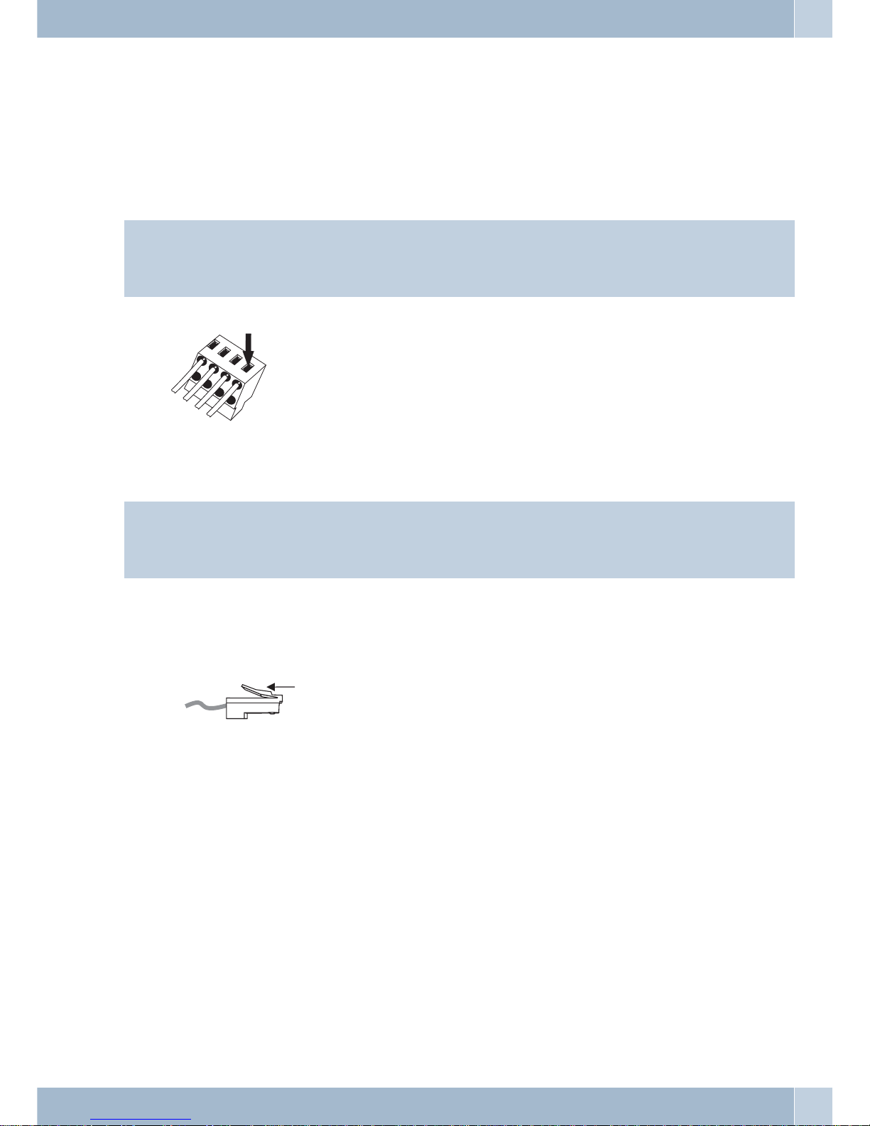
Terminals can be removed from the pins of the cable terminal bay.
Hinweis
In all work on the PABX system ports, you must first turn off the PABX electricity supply and put the external sys-
tem ports out of operation!!
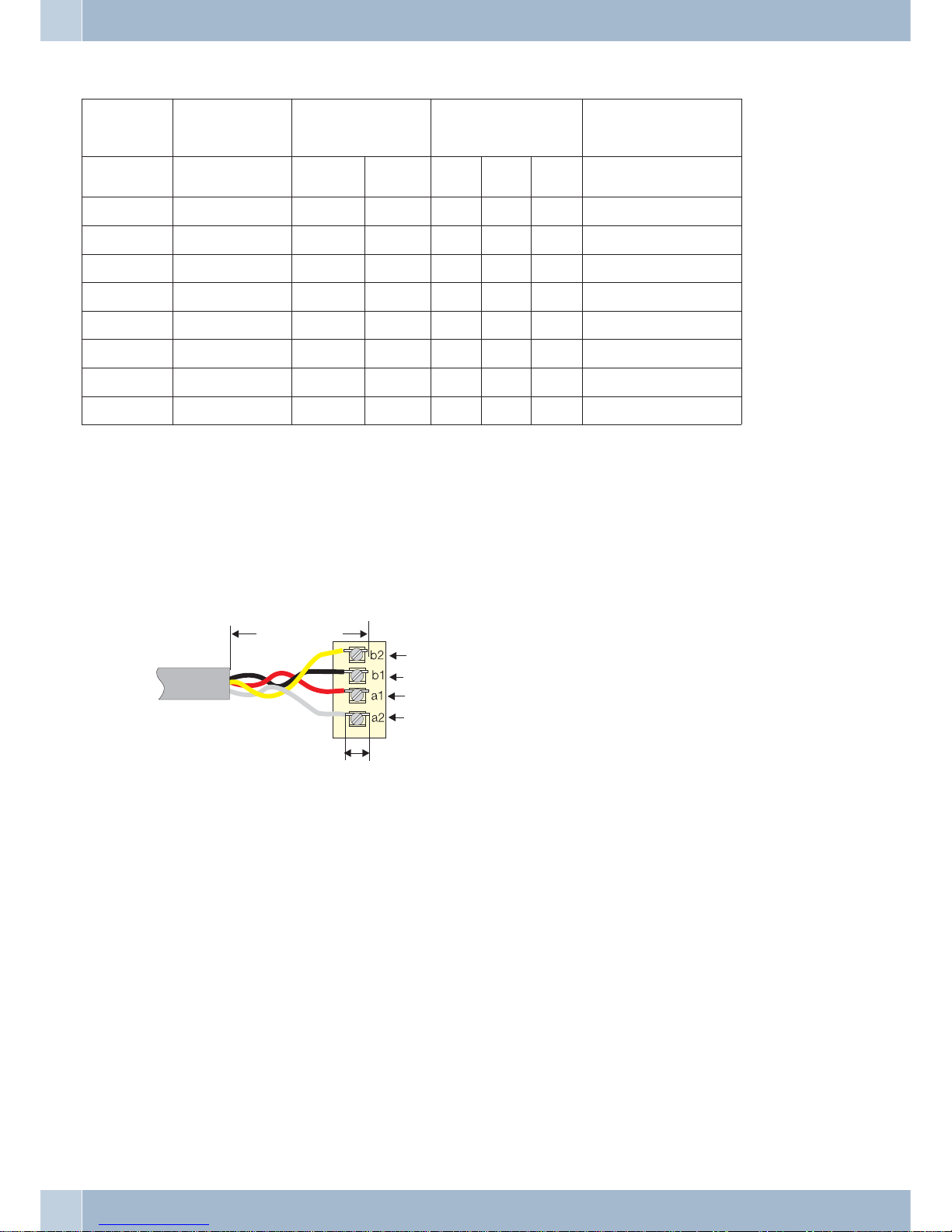
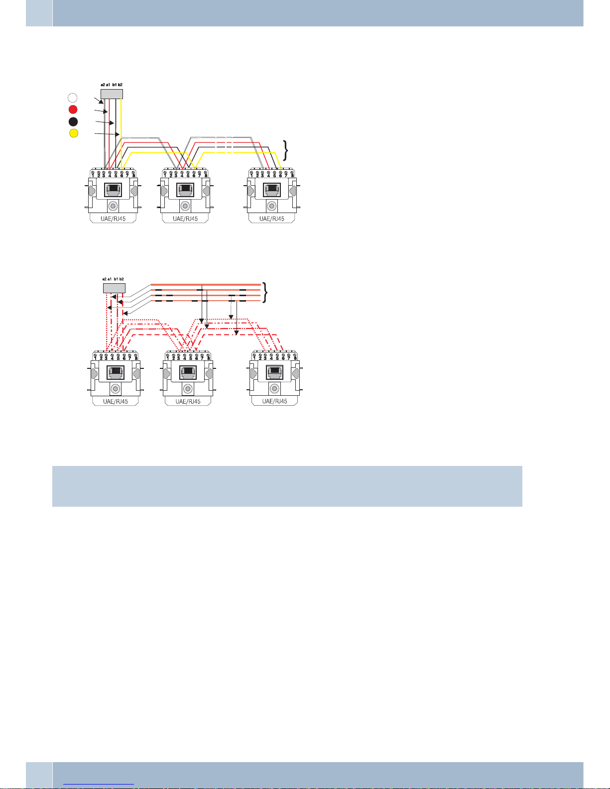
These terminals are for use with ISDN and analog connections. 2 wires can be connected to
every connection. Wire diameters can range from 0. 4 to 0. 8 mm. The wire end to be inserted
must be stripped of 6 to 7 mm of its insulation. The wires can be removed if pressure is ap-
plied with a screwdriver to the terminal bay area designated with an arrow and the wires are
removed by pulling lightly .
RJ45 connector
Hinweis
The RJ45 connectors are locked after being plugged into the ISDN jack to prevent them from being pulled out. The
lever points up after being plugged into the PABX.
Plug the RJ45 connector into the ISDN jack until you hear an audible »Click«, indicating that it is securely locked in.
To unlock press on the small lever on the RJ45 connector while pulling the connector out.
Lever.
Connecting leads
For the function of the PABX terminal devices, the installation lines are veryimportant. Operational safety, disruption sensitivity and range
are dependent upon the type of line and how it is laid. Please only use the prescribed types of lines and comply with the manufacturer’s in-
stallation instructions for the jacks. To the extent that such is possible, you should use the connecting cord supplied. The lines for the PABX
connections may not be laid out in the open as this represents a power overload danger as can occur during thunderstorms.
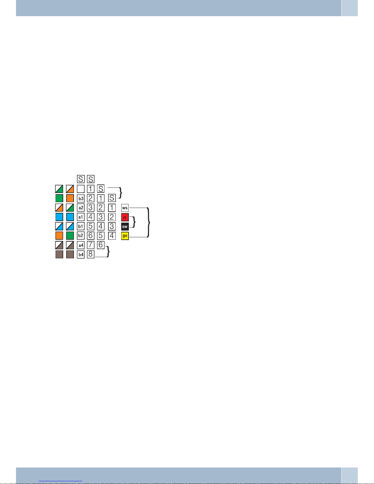
Line types for firm cabling
Installation-grade cable
This cable is sold in two-pair (4-wire) and multi-pair models. Both cables can be used shielded or unshielded. For the connection, one (ana-
log connection or UP0-connection) or two cable pairs (ISDN connection) must always be connected. The cable pairs are »twisted« together
Terminals Installation
1
1