Funn Ripper Quick start guide

INSTALLATION AND USE
Pedals have 9/16" x 20T threaded axles. The right pedal is installed in a clockwise
direction. The left pedal is installed in a counter-clockwise direction.
1.Lightly lubricate axle threads with grease or oil.
2.Thread axle into the crank hole with your fingers. From the other side of the crank,
insert 8 mm Allen key into the recess of the axle. Screw pedal axles onto crank
arms.
3.Tighten to 34 Nm (300 lb-in) torque and avoid excessive force.
ATTACH PEDALS TO CRANKS
GRIP PINS
You can remove the pins on the pedals to fine tune the grip. Damaged or worn grip
pins can be replaced using 4 mm socket wrench.
8mm Hex Key
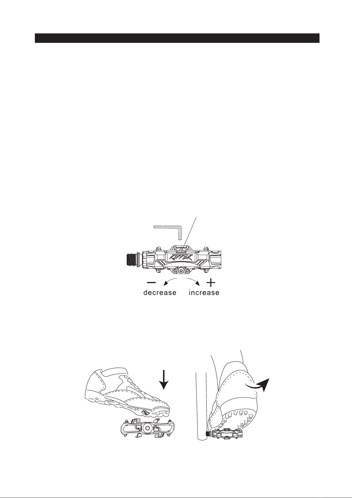
SHOE/PEDAL USE
The tension adjuster is located on the rear binding. To adjust binding tension, use a
3 mm Allen key to turn tension adjuster.
1.Increase tension in a clockwise direction
(+) (for a more secure shoe/pedal bind, but more difficult engagement and
disengagement).
2.Decrease tension in a counter-clockwise direction
(-) (for less secure shoe/pedal bind, but easier engagement and disengagement).
Engage cleated shoes in pedals by aligning the cleat between front and rear
bindings while pushing down. Disengage by twisting heel outwards (away from
bicycle). Cleat will also release by twisting heel inwards if necessary (for emergency
situations only).
Binding adjustment range
8-14 Nm(69–121 lb-in)
Adjustable
rear binding
tension
3mm Hex Key

ATTACH CLEATS TO CYCLING SHOES
Left and right cleats are identical.
1.Lightly lubricate cleat bolt threads with oil.
2.Using the 4 mm Allen key to attach cleat bolts and cleat washers loosely to shoe
soles. The lateral center line of the cleat should be aligned with the center of the
ball of the shoe sole. Adjust vertically via slots in shoe sole. Adjust horizontally via
play between cleat washer and cleat.
3.Tighten the cleat to 5-8 Nm (44–70 lb-in) and avoid excessive force. Cleat position
can be fine-tuned to preference after trial rides. It may take several rides to find
your optimum cleat set-up.
Tightening torque
5-8 Nm(43–69 lb-in)
Insole
Flat nut
Insole
washer
Adjust cleat vertically
and horizontally 4 mm Allen key
Cleat
Cleat bolts
Cleat washers
( Remove rubber sole cover )

1.Pedals should be serviced if: rotating pedal emits noise, rotation by hand feels
rough, there is play in the bearings.
2.Bearings should be cleaned and regreased at least once every 12 months, or
at least once every 6 months if riding predominantly in wet conditions.Damaged
bearings should be replaced.
3.Replace pedals with fractures in body.
This product is warranted under normal usage against defects in workmanship
and materials to the original purchaser for one year from purchase date.
1.User assumes all risk of personal injury, damage to or failure of the product when
it is used in stunt or ramp jumping, acrobatics or similar activities.
2.Pedals are warranted for use by an individual rider only. Use by multiple riders, or
in a fitness center will void warranty.
3.This warranty does not cover any incidental or consequential damages, such as
personal injury or any other losses due to accident, neglect, misuse, abuse,
modification, normal wear and tear, improper assembly or maintenance.
4.When returning a defective product for warranty purposes, the claimant must
provide proof of purchase and a written description of damages.
5.There are no other warranties implied except this express limited warranty.
MAINTENANCE
IMPORTANT NOTES

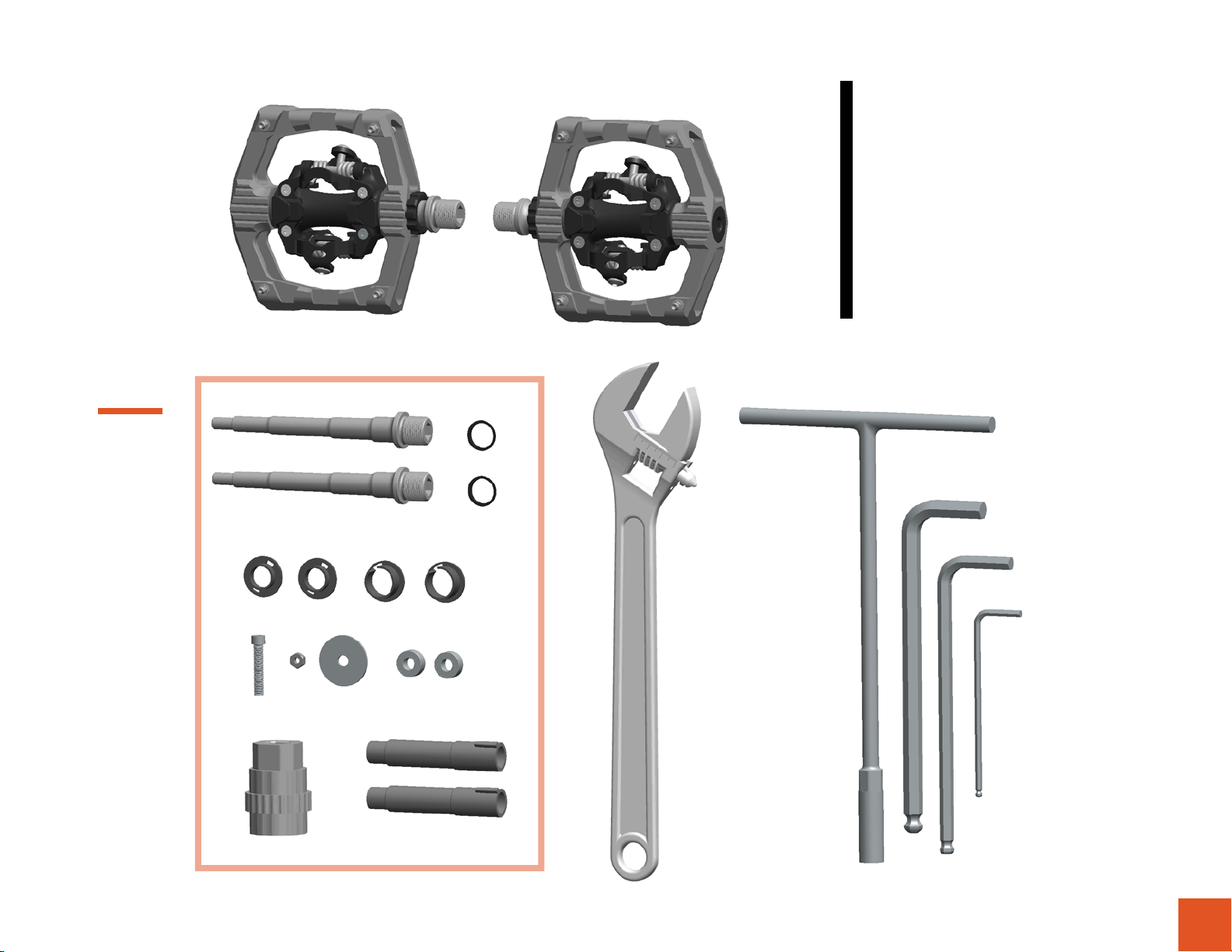
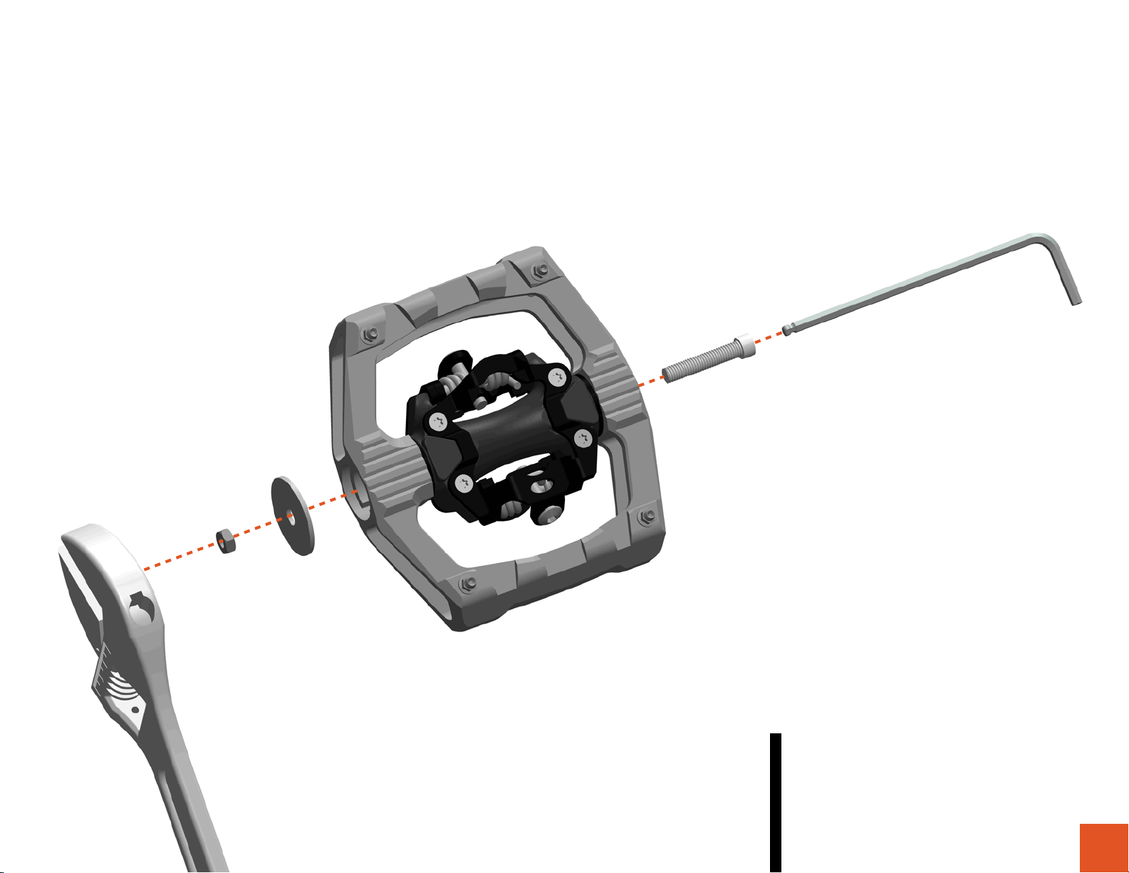
Bearing / Axle Replacement
RIPPER
PEDAL
( Disassembly )
1
1. Use good quality tools to avoid stripping
screw sockets.
2. When servicing your pedals, work on
one side at a time to prevent parts from
mixing up.
3. Reverse threads are indicated by
drawings from both sides of the pedal.
Please pay special attention when
working on these pats.
8mm Hex Key
6mm Hex Key
3mm Hex Key
8mm Socket Wrench
New Axle
New Dust Seal
New Bearing
4mm screw
Nut
Spacer
New Washer A New Washer B
New Bushing
Special Tool Adjustable Wrench
Axle Kit
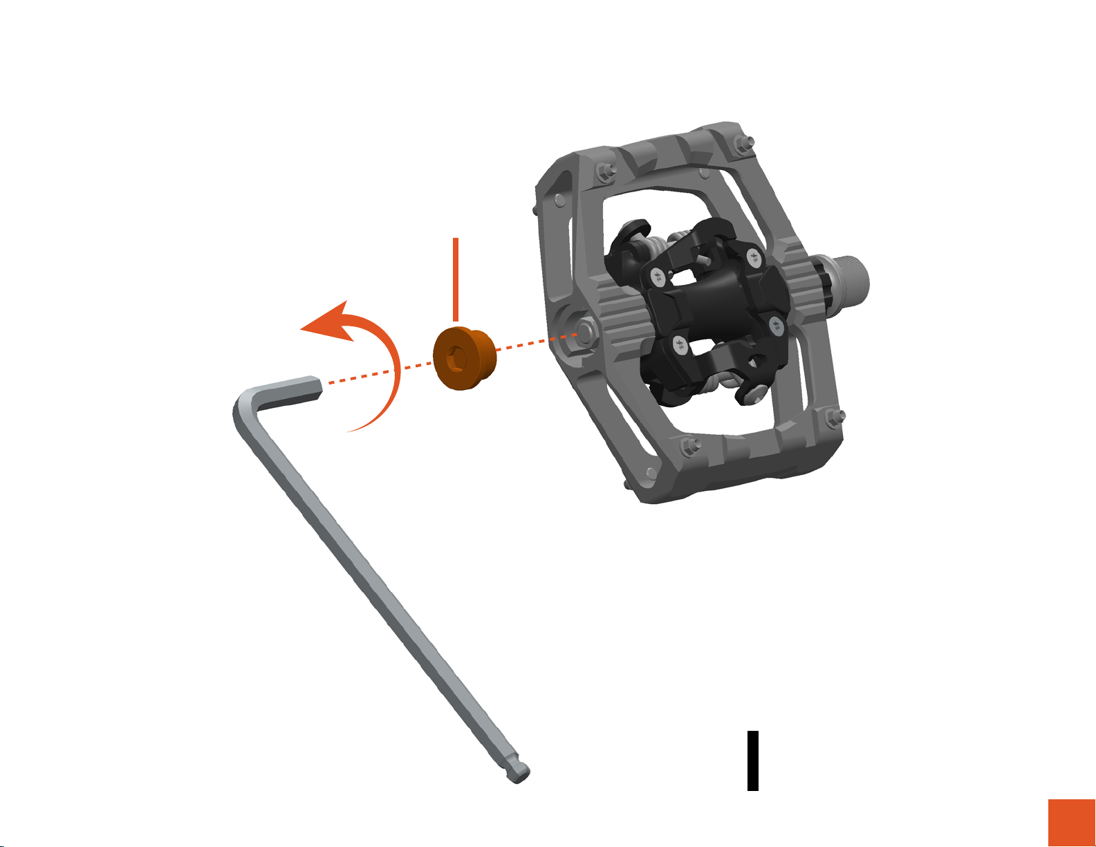
6mm Hex Key
Cap
2
Unscrew side cap with 6mm hex key.
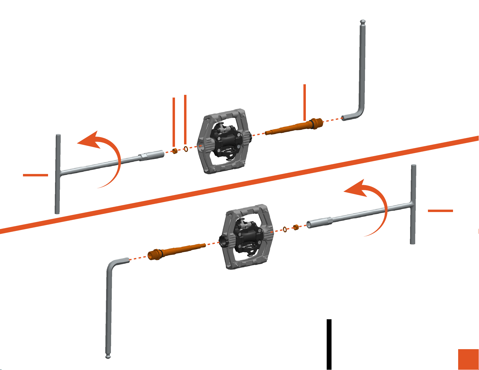
Right
Left
Axle
Spacer
Nut
8mm Hex Key
3
Use 8mm hex key to hold the axle in place;
then unscrew the hex nut by using the
8mm socket wrench. Please note the
thread direction on each side of the pedal.

4
Bushing Screw
Unscrew the bushing cap with the special
tool included in the axle kit or Shimano
TL-PD40 tool.
5
3mm Hex Key
In this step we will remove the bearing from
inside the pedal. First, insert the M4 screw
into the pedal with the 3mm hex key, and
assemble the washer and nut onto the M4
screw.
Other manuals for Ripper
1
Table of contents
Other Funn Bicycle Accessories manuals


