Furman ASD-120 User manual

Owner’s Manual
MODEL ASD-120
1-9842 © 1998 FURMAN SOUND, INC. 960126-2294
Sequenced
Power Distro,
120A

ASD-120 SEQUENCED POWER DISTRO
2
Quick Start ..................................................................... 3
Introduction .................................................................... 4
Features ......................................................................... 4
Description ..................................................................... 4-5
Wiring Instructions.......................................................... 5-8
Controlling On/Off Sequence ......................................... 8-10
Remote Operating Modes .............................................. 11-12
Setup for Remote Operation .......................................... 12-15
Compatibility with other Furman Products ..................... 15
Specifications ................................................................. 16
ASD-120 Block Schematic Diagram .............................. 17
Limited Warranty ............................................................ 18
Service ........................................................................... 18
Other Furman Products ................................................. 19
SAFETY WARNINGSAFETY WARNING
SAFETY WARNING
The instructions provided here are insufficient for completing a working
ASD-120 installation. While the subject of attaching a supply cable to the
ASD-120 is covered, the connection of the far end (pigtail end) of that cable to a
power source is not. Because of the many configurations that 120 amp or larger
electrical services can take and the numerous connector types that may be used,
it is not possible to adequately describe every situation that may be encountered.
Therefore, it is strongly recommended that the selection of the ASD-120
supply cable, and the connections to both ends of it, be done by a licensed
electrician who is familiar with the available electrical service.
Contents

ASD-120 SEQUENCED POWER DISTRO 3
STATUS
START
REM
FORCE
ON
REM
COM
GND
RELAY
COM
MOMENTARY
REMOTE SWITCHES
F
B
C
D
E
+12V FORCE
OFF A
STATUS
START
REM
FORCE
ON
REM
COM
GND
RELAY
COM
F
B
C
D
E
+12V FORCE
OFF A
ON OFF
LATCHING (MAINTAINED)
REMOTE SWITCH
Quick Start
The illustrations below show several of the most common hookup methods for
the ASD-120. There are many other methods and features, however, so please
refer to the rest of this manual for more details if necessary.
For single unit operation with turn on from local or one remote location. Default
is maintained contact closure.

ASD-120 SEQUENCED POWER DISTRO
4
Introduction
Congratulations on your purchase of a Furman ASD-120 Sequenced Power
Distro. Please read this manual completely before installing your ASD-120.
Features
●120 amp total load
●Six 20 amp, 120 volt circuits, each with a STATUS indicator
●Four buss design accommodates 120/240V single phase, or 208V three
phase power
●Six 20A duplex outlets on rear panel
●Outlets are powered up and down in sequence
●Three position ON/SEQ/OFF switch per circuit allows each circuit to be part of
the power sequencing, or to be switched on/off independently
●Sequence on/off can be initiated from unit or remotely
using almost any type of control wires
●Six separate, low level relays provide contact closure (or opening) to control and
sequence other units, such as additional ASD-120’s, Furman PowerPorts,
MiniPorts, PowerLinks and the PS-8R and PS-PRO Power Sequencers
●Front panel key switch for security
●Six LEDs on the front panel show status of each circuit
●STATUS indicators for each incoming phase
●Basic MOV spike and surge suppression
●Compact two rack space package
Description
The ASD-120 is an extremely compact, low cost rackmount power distribution
system that is ideal for touring PA systems, touring musical and theatrical acts,
mobile recording facilities, on-location film and video shoots, etc.—any situation
where AC power must be distributed to multiple circuits and a hard-wired, built-in
system is missing, inadequate, or impractical. Use of a Power Distro is cost-effec-
tive, both in terms of the convenience it offers and the elimination of bulky and
expensive parallel feeds and related connectors.
The ASD-120 is a Sequenced Power Distro. It can handle up to 120 amps of
incoming power, distributing it to six 20 amp, 120V circuits. Each circuit has a front
panel STATUS indicator that lights up when it is turned on, and a 20 amp duplex
outlet on the rear panel. The ASD-120 allows you to sequentially power up and
down its six rear panel duplex outlets, each of which is protected by a 20-amp
thermal breaker. The delay interval is user-adjustable via an internal trimpot.
Power sequencing is needed whenever various kinds of equipment must be
powered up or down in groups, rather than all simultaneously. In audio systems,
sequenced powering is often necessary to allow turn-on transients from low level
amplifiers and processors to settle down before any power amps are turned on,
because simultaneous powering would result in a loud, annoying, and potentially

ASD-120 SEQUENCED POWER DISTRO 5
destructive “pop” reaching the speakers. And in any large system whose compo-
nents present a large inrush load to the AC line (including electric motors, power
supplies, and power amplifiers of all kinds), sequenced powering can avoid exces-
sive inrush currents that cause circuit breakers to trip even though the steady-state
currents are not excessive.
The ASD-120’s front panel provides a three-position ON/SEQ/OFF switch
for each circuit that allows each circuit to be part of the power up/down sequence,
or to remain on or off independent from the sequence. An LED adjacent to the
ON/SEQ/OFF switch indicates when either the power-up or power-down sequence
is in progress.The sequence can be initiated with either momentary or maintained
switches, locally or remotely. A duplex outlet is provided for each delay step. A
locking switch with a removable key is provided for maximum security.
The sequence can also be controlled by input terminals on the rear panel,
so one or more ASD-120’s may be installed in remote locations and operated
via low-voltage control wiring.As the ASD-120 sequences on, it turns on high power
relays that allow power to flow to the rear panel outlets, and, in the same sequence,
it turns on low level relays that provide contact closures (or openings) that can be
used to control Furman PowerPorts, MiniPorts, PowerLinks, PS-PRO and PS-8R
Power Sequencers, or any other circuits that need to know when their particular
time delay has elapsed. Using one or more ASD-120’s can provide the capability of
controlling power and power sequencing for an entire system. Detailed information
is provided in the Remote Control section of this manual.
The ASD-120 has no line cord or master breaker, and is designed to be perma-
nently wired to a single phase 120/240V source with 60 amps per side capacity, or
to a three phase 120V source with at least 40 amps per phase capacity.
The ASD-120's design incorporates four busses, allowing wiring for 120/240V
single phase, or 208V three phase power. A strain relief clamp is provided that can
accommodate a cable or wire bundle up to 1.5 inches in diameter. Cable termina-
tion is a simple process of breaking out and stripping the individual conductors and
connecting them with set screws, and then tightening the strain relief clamp.
The user-supplied mains supply wiring connects to an internal buss assembly.
As shipped, the unit is configured for 3-phase power. Outlets A and D are supplied
by the Xphase input, outlets B and E are supplied by the Yphase input, and outlets
C and F are supplied by the Zphase input. 120/240V input can be accommodated
by connecting outlets A, C, and E to X, and B, D, and F to Y.The Zinput is not used.
Fast-on connections to the power input buss allow easy reconfiguration.
Please read the Wiring Instructions section of this manual to guide you through
the process of selecting and terminating the supply cable.
Wiring Instructions
Prior to use, the ASD-120 must be fitted with a proper supply cable, which must
then be connected to an adequate power source and disconnect. The following
instructions will guide you through the selection and connection process. All steps
should be done while the unit is disconnected from power and is not mounted in a
rack. Begin by removing the four screws that hold the top cover in place and put the
screws and cover aside.
1. Determine the power source. In North America, there are generally two

ASD-120 SEQUENCED POWER DISTRO
6
possibilities: 120/240V single phase, or 208V three phase. The first alternative re-
quires only four* conductors, but they will need to be heavy to avoid voltage drop in
the cable, making the cable less flexible. 120/240V power is available in most resi-
dential and some commercial sites. The second alternative, three phase, will re-
quire five* conductors which can be lighter gauge, but 3 phase power may not be
available in every building.
2. Select a cable and determine its length. If the ASD-120 is installed in a
permanent or semi-permanent location, it is possible to connect it with flexible metal-
jacketed conduit. However, rubber-jacketed (type S) or neoprene-jacketed (type
SO) cable will usually be preferable in portable use because of its flexibility and
ease of coiling for storage. Another possibility is to use individual wires (such as
welding cable) bundled together every foot or two with plastic ties. The gauge and
number of conductors depends on the supply voltage and cable or wire bundle
length.
Consult Table 1 below to select the cable type best suited for your application:
# Conductors Current Carrying Ground
Including Ground Conductors Conductor
240V ** 4 6 AWG 10 AWG
208V 3-ph *** 5 8 AWG 12 AWG
The “Current Carrying Conductor” and “Ground Conductor” columns give the
minimum recommended AWG size for cable lengths of 100 feet or less. Note that
while it is acceptable for the ground conductor to be a smaller gauge than the
current-carrying conductors, many cables have all conductors the same size. If
they are all the same size, it must be the size specified in the table for the current-
carrying conductors.
The ASD-120’s strain relief clamp can accommodate a cable up to 1.5 inches in
diameter. For reference, a 4 conductor, 2 AWG type S or SO portable cord’s diam-
eter is 1.28 inches.
If the cable is to be moved from location to location frequently, we suggest you
make it at least a few yards longer than the length needed for the most distant
location. This is because the source end will often be left as “pigtails”—that is, with
the outer jacket stripped off a few feet and no connectors attached.When the elec-
trician makes the connection to the power source, he or she will often cut a few
inches off each conductor to expose clean copper to assure a reliable connection.
In this way, the cable will become slightly shorter with each use.
3. Prepare and connect the cable: The supply cable will be connected to the
ASD-120’s buss bars via terminals that secure the individual conductors with set
screws. These can accept wires as large as 2 AWG. Strip one end of the cable to
expose the wires. When removing the outer jacket, be careful not to nick or cut into
*Including ground, assuming the system neutral must be kept separated from the
safety (chassis) ground.
** Assumes three 20-amp loads on one conductor and three 20-amp loads on the
other conductor.
*** Assumes two 20-amp loads on each of the conductors.
Table 1, Required Wire Gauges

ASD-120 SEQUENCED POWER DISTRO 7
ASD-120 Buss Bar Block
the insulation of the individual conductors. When stripping the individual conduc-
tors, be careful not to cut through any of the copper strands. All of the individual
conductors should be stripped one-half inch. Please see table below for individual
wire lengths.
For 3 phase wiring, the following conductors are needed: Ground = Green or
Green with Yellow Stripe. X, Y, Zphases: There is no standard that matches colors
to letters, but X = Black, Y = Red, and Z = Blue can be used as a reference. W=
Neutral and is always white. For 240V Single phase, Ground = Green or Green with
Yellow Stripe, X = Black (hot), Y = Red (hot), W = White (neutral). 120V/120A
service is not expected to be used much, if at all, with this product, however, Ground,
X, and W are used just as in 240V Single phase.
After threading the cable end through the strain relief clamp, connect the stripped
conductors to the buss bar block. Be sure to put each wire in the lower part of its
terminal, so that it is compressed above and below by copper rather than by the set
screw itself. Tighten the set screws securely.
4. Divide the load: Since there is more than one hot wire, the six 20 amp loads
must be split among them and balanced as well as possible.This is done by recon-
necting the wires from the buss bars to the six circuits.There are two wires to each
circuit, a hot (black) and a neutral (white). Only the black wires may be moved. All
white wires must connect to the NEU (neutral) buss bar.
Each black wire is labeled with a letter (A, B, C, D, E, or F) corresponding to the
circuit it goes to.The connections are made by Fast-On terminals on the buss bars.
Table 2, Suggested Cable Strip Lengths
Color of Wire Wire End Stripped Total Length of Wire
WHITE (NEU) .5 inch 6.0 inches
BLUE (Z) .5 inch 5.0 inches
RED (Y) .5 inch 4.0 inches
BLACK (X) .5 inch 4.0 inches
GREEN (Ground) .5 inch 4.0 inches

ASD-120 SEQUENCED POWER DISTRO
8
To reconnect a wire, grasp it by the terminal and pull straight up. Then reposi-
tion it over an unused Fast-On male terminal on the appropriate buss bar and push
down firmly. Wire the loads in accordance with Table 3.
5. Tighten clamp and close unit: Tighten the cable strain relief clamp firmly. If
you are using a cable, make sure about a half inch of the outer jacket extends
beyond the clamp into the unit. If you are using a wire bundle, it is a good idea to
wrap the bundle with several layers of heat shrink tubing or other sturdy material at
the point where the clamp tightens, to minimize the likelihood that the clamp will cut
into the insulation of the individual wires. Review your remote control options and
set control jumpers as required (see Table 3). Replace the top cover. This com-
pletes the internal wiring of the ASD-120.
6. Terminate source end of cable or wire bundle: As mentioned in item 2
above, the most common cable termination is to break the ends out as pigtails and
leave its hookup to the house electrician in each venue. In some circumstances, a
suitable connector may be provided at the power source and the cable can be
terminated with a mating connector. Often these will be Cam-Lok® or similar con-
nectors for each individual conductor.
If you want to provide a way to disconnect the cable from the ASD-120 for
separate storage or shipment, one good way is to permanently attach a very short
cable to the ASD-120 and terminate it with Cam-Lok, Meltric, or similar high-current
connectors. A long cable with mating Cam-Loks would then be prepared which
could easily be disconnected and stored. A good source for custom made high
power cables is “J” Custom Supply, telephone 1-800-226-5657 (1-800-CAM-LOKS).
7. Set internal jumpers to suit your application: See Table 4 on page 10.
Controlling On/Off Sequence
A normal, time-delayed on or off sequence may be initiated in either of two
ways: locally, via the front panel key switch, or remotely, via a remotely located
maintained or momentary switch connected to the ASD-120’s rear panel terminal
strip. In addition, the behavior of any individual circuit may be overridden by its
corresponding front panel ON/SEQ/OFF toggle switch.
The ASD-120’s control circuits turn on the outlets in order from A to F when
sequencing on, and turn the outlets off in the reverse order from F to A when se-
quencing off. The time for each step is internally adjustable with a trim pot, with a
range of 0.2 to > 12 seconds per step. (Total time for the entire sequence is from 1
second to > 1 minute).
Local control: Turning the key to the ON (or possibly REM) position initiates an
Table 3, Dividing The Load
Input Color Cable Buss Bar Circuits
120V or 240V Black XA, C, E
Red YB, D, F
208V 3-ph Black XA, D
Red YB, E
Blue or Orange ZC, F

ASD-120 SEQUENCED POWER DISTRO 9
on sequence. Please note that in the absence of any signal applied to the remote
input, the REM position defaults to on. (If the ASD-120 has been changed from the
factory-preset Maintained Mode to Momentary Mode, you must also press the START
ON/OFF SEQUENCE button. However, for purely local control, you should leave
the mode set to Maintained.)
When the unit is turned on with the key switch, the ASD-120 will stay on if all
outlets are already on, or, if all outlets are off, will begin turning on outlets starting
with outlet A, then B, etc. until all outlets are on. If the unit was in the middle of
sequencing off and had not yet turned off all outlets, the lowest outlet that was
currently off will go on, so the sequence reverses without ever deactivating the
outlets that had not yet gone off. The lowest off outlet turns on within 0.2 seconds,
regardless of the setting of the delay time trimpot. The next and all following outlets
turn on at intervals controlled by the trimpot. The factory default setting is approxi-
mately 1 second per step.
When the unit is turned off with the key switch, the ASD-120 will stay off if all
outlets are already off, or, if all outlets are on, will begin turning off outlets starting
with outlet F, then E, etc. until all outlets are off. If the unit was in the middle of
sequencing on and had not yet turned on all outlets, the highest outlet that is cur-
rently on will go off, so the sequence reverses without ever activating the outlets
that had not yet turned on. The highest on outlet turns off within 0.2 seconds, re-
gardless of the setting of the internal delay time trimpot. The next and all following
outlets turn off at intervals controlled by the trimpot.
Remote Control: In the REM (center) position, an on or off sequence is initi-
ated by one or more switches connected to the rear panel inputs, or, in Momentary
mode, also by the START ON/OFF SEQUENCE button. The ASD-120 responds
exactly as it does as described in the preceding section on local control. See the
next section for a discussion of Remote Operating Modes.
When the key is in either the ON or OFF position, the ASD-120’s sequencing
circuits will not respond to the rear panel remote control inputs. If the key switch is
later returned to the REM position, the signals supplied to the rear panel remote
inputs will again control the unit.
Overriding a sequence: The ASD-120 outlets are turned on and off by high
power relays. The relays are controlled by drivers that can be activated either by
the internal control circuits, or directly by a three-position toggle switch.The six ON/
SEQ/OFF toggle switches (one per outlet) can override the sequencing circuits,
and are intended as a secondary means of control to allow individual on/off control
of each outlet for diagnostic purposes. Following are the three positions of each
ON/SEQ/OFF toggle switch. Up: Outlet is on regardless of state of sequence con-
trol circuits. Center: Outlet is controlled by the sequence circuits (the normal posi-
tion). Down: Outlet is off regardless of state of sequence control circuits.The center
position is the normal operating position, and allows control by the sequencing
circuits.
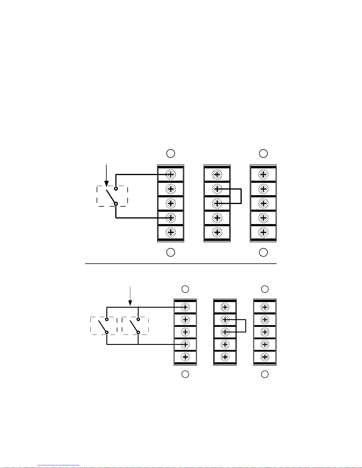
Signal relays: The ASD-120 also has six low level signal relays, accessible by
the rear panel terminals labeled A through F, that are powered by the same drive
that turns on the AC power relays for the six duplex outlets. These signal relays
have an isolated common (labeled RELAY COM) that is independent of the chassis
and signal grounds of the ASD-120, for easy interfacing to virtually any other de-
vice that could act as a slave to follow the ASD-120.
There is an internal jumper for each signal relay that allows selection of the

ASD-120 SEQUENCED POWER DISTRO
10
normally closed or normally open contacts between each of the A to F terminals
and RELAY COM. The factory default is that the contacts are open when the asso-
ciated outlet is off (normally open).
The relay contacts may be easily converted to normally closed operation by
moving six “suitcase” jumpers on the ASD-120’s circuit board. To do this, first dis-
connect the unit from AC power. Remove the four screws that secure the top cover.
There are twelve small two-pin connectors labeled J1 through J12, located near
the left side of the largest circuit board. Six of the twelve are joined by small black
suitcase jumpers. To change the mode, gently pull them up and reposition them in
accordance with Table 4 below. Replace the top cover and screws.
Table 4: Internal User Settable Jumpers
JMP1 Momentary Mode
JMP2 Maintained Mode, Normally ON (Factory Default)
JMP3 Maintained Mode, Normally OFF
NOTE: Connect only one jumper of the JMP1-JMP3 group at a time.
J1,2,5,6,9,10 Normally Open jumper positions for signal (low level)
relays A,D,B,E,C,F respectively (factory default)
J3,4,7,8,11,12 Normally Closed jumper positions for signal relays
A,D,B,E,C,F respectively
NOTE: Connect one set of six jumpers of the J1-J12 group at a time
ASD-120 front panel (top) and rear panel (bottom)
120 VAC
60HZ
MAX LOAD
20A
INPUT 120 / 3 208 / 240 VAC
14400 WATTS
120 AMPS MAX
WARNING! ELECTRIC SHOCK HAZARD.
CONNECTION OF A POWER INPUT CABLE
TO THIS DEVICE AND TO A POWER SOURCE
MUST BE DONE BY QUALIFIED PERSONNEL
ONLY.
AVIS:
RISQUE DE CHOC
ELECTRIQUE -- NE PAS OUVRIR
RISK OF ELECTRIC SHOCK.
DO NOT OPEN. REFER
SERVICING TO QUALIFIED
SERVICE PERSONNEL. TO
REDUCE THE RISK OF FIRE
OR ELECTRIC SHOCK DO NOT
EXPOSE THIS EQUIPMENT TO
RAIN AND MOISTURE.
CAUTION!
MADE IN THE USA
AB
C
FED
B

ASD-120 SEQUENCED POWER DISTRO 11
Remote Operating Modes
If the ASD-120 will be controlled locally only, you may skip this section and the
next section of the manual.
There are three remote operating modes available: Maintained Mode/Normally
On, which is the default, Maintained Mode/Normally Off, and Momentary Mode.
The Momentary Mode on the ASD-120 shares the same characteristics as the
Momentary Mode on the Furman PowerPort, MiniPorts, PowerLink and PS-PRO
and PS-8R Power Sequencers. Remote inputs (REM, FORCE ON, FORCE OFF)
are controlled by applying at least 5 VDC or 6 VAC between the input and the REM
COM terminal.
This is the default control logic on all of our existing and past power products.
However, the ASD-120’s inputs are enhanced in the following ways: (1) They are
polarity independent, and work with positive, negative or AC control signals.
(2) They are optically isolated. The remote control inputs have a floating common.
(3) They safely accept up to 130 VAC, for direct control from mains supply.
Maintained Mode/Normally On (Default)
In the absence of any signal applied to the remote input, the ASD-120 will se-
quence on as soon as power is applied, and the key switch is turned to REM
or ON. This is Maintained Mode/Normally On. In this mode, voltage must be con-
tinually applied to the REM input to keep the ASD-120’s outlets off, when the key
switch is in the REM position. This mode is compatible with all other Furman prod-
ucts’REM inputs.
ASD-120 front panel (top) and rear panel (bottom)
+12V
STATUS
START
REM
FORCE
ON
FORCE
OFF
REM
COM
GND
RELAY
COM
F
A
B
C
D
E
LOAD
0
AAVIS:
RISQUE DE CHOC
ELECTRIQUE -- NE PAS OUVRIR
RISK OF ELECTRIC SHOCK.
DO NOT OPEN. REFER
SERVICING TO QUALIFIED
SERVICE PERSONNEL. TO
REDUCE THE RISK OF FIRE
OR ELECTRIC SHOCK DO NOT
EXPOSE THIS EQUIPMENT TO
RAIN AND MOISTURE.
CAUTION!
MADE IN THE USA
AB
ED

ASD-120 SEQUENCED POWER DISTRO
12
Internal jumpers allow selection of either of two other optional modes, as de-
scribed below. Please also see Table 4, Internal User Settable Jumpers, on page
10.
Maintained Mode/Normally Off
This mode is just the reverse of the Maintained Mode/Normally On mode. The
ASD-120’s outlets stay off until voltage is applied to the REM input. Voltage must
be continually applied to keep the unit on, when the key switch is in the REM posi-
tion. This setting will be useful to interface to other brands of controller that have
positive control logic (i.e. they put out a signal to indicate that attached gear should
turn on). In addition, since the REM inputs are optically isolated, and designed to
accept up to 130 VAC, this mode allows the ASD-120 to sequence on if some other
source of AC line voltage is turned on.
Momentary Mode
In Momentary Mode, the ASD-120 has “memory”—it only needs a momentary
signal to change its state from on to off, or off to on.When first plugged in (or after
power is lost and reapplied for any reason) the “memory”state is off. It will stay off
until sequenced on by the front panel START ON/OFF SEQUENCE pushbutton or
a momentary connection of the REM IN terminal to a voltage source of at least ± 5
VDC or 6 VAC (130V max). The sequence starts on the rising edge of the signal.
The rear panel +12V output may be used as a trigger source. This is further ex-
plained in the section “Setup for Remote Operation”below.
Once the ASD-120 is on (or is sequencing on), applying voltage momentarily to
the REM input starts switching the ASD-120 off, in descending sequence. Pushing
the START ON/OFF SEQUENCE button on the front panel is effectively the same
as applying a signal to the REM input (although the actual connection is applied to
an internal node, not to the REM terminal on the rear barrier strip).
In Momentary Mode there are two additional inputs that are not required, but
may be useful where multiple ASD-120’s are controlled from remote locations. Please
see the section “Compatibility with Other Furman Products”later in this manual.
Setup for Remote Operation
The barrier terminal strip on the ASD-120 rear panel allows a switch (or switches)
to be connected to turn the unit on and off at a distance, and provides various
power, status and relay closure outputs. In the most basic configuration, only two
Class 2 wires and an SPST switch are needed to initiate an on or off sequence.The
switch may be either a momentary or maintained-contact type. An LED may also
be installed at the remote end to indicate power is on, but will require a third wire.
Momentary vs. Maintained Contact Switching
An on-off switch of either kind may be used to actuate the ASD-120’s remote
operation. Maintained switches, such as most toggle switches and push-on/push-
off button switches, and including the Furman RS-1 wall mount key lock switch, are
open until actuated, then stay closed until actuated again. Momentary switches,

ASD-120 SEQUENCED POWER DISTRO 13
including the Furman RS-2 switch, are usually pushbutton types that are normally
open and stay closed only as long as the button is pressed.
Maintained switches are generally most convenient when there is only one
remote location. When more than one location is required, momentary switches
offer the advantage that either the turn-on or the turn-off sequence may be started
from any location.
The ASD-120 is shipped factory-set for maintained operation. It may be easily
converted to momentary operation by moving a jumper plug on the ASD-120’s
circuit board. To do this, first disconnect the unit from AC power. Remove the four
screws that secure the top cover. There are three small two-pin connectors near
the center of the largest circuit board. A small black suitcase jumper can be moved
to set the mode. (Please see Table 4 on page 10 for jumper numbers and function
description.)
Maintained Mode/Normally On
A simple connection of the REM IN terminal to the +12V terminal initiates an
OFF sequence. Disconnecting it initiates an on sequence. If the cable run is long,
it is recommended that the REM IN wire be tied to the ASD-120’s GND terminal
during on operation rather than leaving it floating.This will require the use of a third
conductor and a double-throw switch. NOTE: The REM COM is floating with re-
spect to the ground of the +12V source. To use the +12V with the REM input, the
REM COM terminal must be connected to the adjacent ground terminal on the rear
barrier block. In Maintained Mode, do not use the START ON/OFF SEQUENCE
button on the front panel.If you do press the button, the ASD-120, if on, will start an
off sequence that will last only until you release the button.
Maintained Mode/Normally Off
A simple connection of the REM IN terminal to the +12V terminal initiates an on
sequence. Disconnecting it initiates an off sequence. The other instructions are
identical to those in the Maintained Mode/Normally On section above. Again, do
not use the START ON/OFF SEQUENCE button on the front panel. If you do press
the button, the PowerLink, if off, will start an on sequence that will last only until you
release the button.
Momentary Mode
A momentary connection of the REM IN terminal to the +12V terminal will start
the ASD-120’s on/off sequence. The +12V output on the rear barrier strip can be
used to trigger the REM input. As in Momentary mode, the REM COM must be
connected to the adjacent GND terminal.This mode also requires only two wires in
the simplest case, +12V and REM.You may wire any number of momentary switches
in parallel. In this mode the START ON/OFF SEQUENCE button can also be used
to trigger an up/down sequence.
Status Output
In all models, the STATUS terminal is an output that may be used to illuminate
an LED at the remote location to indicate that power is available at the ASD-120’s
outlets. If it is high (+12V), the unit is on (or at least in the process of sequencing

ASD-120 SEQUENCED POWER DISTRO
14
on); if low, the unit is off (or sequencing off). Simply connect the indicator LED
between STATUS and GND (a series resistor is not required). If the LED does not
light when the switch is in the ON position, check the polarity and reverse the LED
leads if it is wrong. If a Furman RS-1 is the controlling switch, contact Furman’s
Tech Support department for the proper wiring diagrams. The STATUS output is a
12V source, current limited to 10 mA. If you wish to use the STATUS output as a
voltage signal to some monitoring device, and also wish to light a status LED on a
remote panel, put a 1 K Ohm 1/4-watt resistor in series with the LED.
Multiple Units
You can use more than one ASD-120 to handle loads that exceed 120 amps.To
control them remotely with one or more remote switches, connect the REM and
REM COM terminals of all units together.You might need to connect the +12V or
GND terminals. Be sure that the mode (momentary or maintained) of all units is set
the same. Connect a single maintained switch or one or more momentary switches
to the nearest ASD-120, as discussed in the sections above.To avoid tripping house
breakers, the power input for each ASD-120 should come from a separate service.
If you are unsure whether your building wiring can accommodate multiple fully-
loaded ASD-120’s, consult a qualified electrician.
Because the trigger sources provided on the rear of the ASD-120 (START and
+12V) have a GND that is isolated from the REM COM, it may be necessary to
connect GND to REM COM on all units.This will usually be needed.The GND and
REM COM would be left isolated if the ASD-120(s) are to be signalled by some
other source of voltage, such as the AC line, or a third party controller. The +12V
output or the START output on a single ASD-120 has enough output current to
switch dozens of REM inputs simultaneously, however, it is harmless to parallel the
+12V outputs.
If multiple ASD-120’s are controlled by one or more momentary remote switches,
they will all change state (from on to off or vice versa) on each rising edge of
the voltage on the REM input terminal. Pushing the START ON/OFF SEQUENCE
button will affect only the local ASD-120 unless the START terminal on the rear
barrier strip of each unit is connected to the REM terminal directly below it.To keep
all units in sync, please be sure to make this connection on all units. Once the
START and REM terminals are connected on all units, any remote switch and any
of the START ON/OFF SEQUENCE button on any unit's front panel will toggle all
the units.The key switch on each unit’s front panel will turn off (or on) any individual
unit without affecting the other units.
The STATUS lines work the same in either mode. Each reflects the true state of
the sequence control circuit of its unit, and is affected by both the “memorized”
state and by the front panel key switch. A separate LED must be used to indicate
the status of each ASD-120.NOTE:The STATUS line will not reflect changes caused
by the ON/SEQ/OFF mini-toggle override switches. The STATUS output only indi-
cates if the sequencing control circuits are set to on or off.
To take care of the special (hopefully rare) case of having several ASD-120’s in
parallel that somehow get out of sync such that every time a remote button is pushed,
some units turn on and others turn off, there is a special feature of the REM signal
line: Pushing the “START ON/OFF SEQUENCE”button and holding it down for
four seconds, or holding the REM line high for at least 4 seconds will force all units
to the off state, which will put them back in sync. This may be the only way to re-
sync units other than disconnecting AC power to all the units. Remember —oper-

ASD-120 SEQUENCED POWER DISTRO 15
ating the front panel key switch does not affect the stored state of the unit, even
though it does temporarily turn the outputs off. Please refer to the “Compatibility ...”
section of this manual below for another way to keep ASD-120’s in sync.
Additional Remote Features:
●STATUS output signal on the rear panel allows remote indication of whether the
unit is on or off (high indicates the unit is on or sequencing on, low that the
ASD-120 is off or sequencing off)
●+12V output terminal on rear has 40 mA capacity to power many external devices
●+12V supply and STATUS terminals are true voltage sources, with current limiting
circuits that prevent damage if the output is heavily loaded or shorted.This allows
direct connection of an LED to the STATUS output, or if a voltage is desired from
the STATUS output, an external resistor in series with the LED (at least 1K) will
allow the STATUS output to rise to 12 VDC while simultaneously lighting the LED.
●A START output on the rear goes to +12V (with a 1K source impedance) when
the front panel momentary START ON/OFF SEQUENCE push button is pushed.
This allows the ASD-120 to send a signal to other units that can be turned on and
off by a momentary voltage signal. Note: This start function is merged with the
REM input on other Furman products.
Compatibility with Other Furman Products
The ASD-120’s remote control features are similar to those on the PS-8R and
PRO Series with the following enhancements: A separate LED (next to the front
panel START ON/OFF SEQUENCE button and labeled REM ON) shows the “memo-
rized”state.This LED will be on whenever the remote control circuits are set to turn
the unit on, off if the remote control circuits are trying to turn the unit off. (Other
Furman products blink one of their status lights to indicate the remote status.)
Because the remote control inputs are optically isolated, they have a separate
“ground”from the chassis and control logic. In some cases this “ground,”labeled
REM COM, may need to be connected to the signal ground GND. The ASD-120
has three remote input terminals. The REM input is used in both Momentary and
Maintained modes, as described in the previous sections on remote operating
modes. FORCE ON and FORCE OFF work only in momentary mode, and are the
same as the ON and OFF inputs of the PowerPort. If the unit is off, applying power
momentarily to the FORCE ON input will set the memorized state to on, which will
start the on sequence. Applying further control signals (of any duration) to this input
will have no effect. If the unit is on (or sequencing on) applying power momentarily
to the FORCE OFF input will set the memorized state to off, which will start the off
sequence. Applying further control signals (any duration) to this input has no effect.
The FORCE ON and FORCE OFF inputs provide an assured method of con-
trolling multiple ASD-120’s, with no possibility that the units will get out of sync with
each other, as can happen when using the regular REM toggle input. These two
inputs also make the ASD-120 directly compatible with the PowerPort. As is the
case with the PowerPort, the disadvantage of using the separate ON and OFF
inputs instead of the single REM toggle input is that two momentary switches (and
at least three wires) are required at every remote control location.
Where a single ASD-120 is controlled from multiple remote locations there is no
advantage to using the separate ON and OFF inputs, unless the switch location
makes it difficult for you to tell whether the system is currently on or off.

16
VOLTAGE AND CURRENT Input Current: 120 amps
Input Voltage: 120/240V single phase, or 208V 3-ph.
Output: Six identical 20 amp, 120V circuits
CIRCUIT BREAKERS Thermal, 20A
POWER SEQUENCING Delay Interval: 0.2 to 10 seconds per step
(adjustable with internal trimpot)
REM CONTROL INPUTS Optically isolated, AC or DC drive, 12K ohm input
impedance. Operates at 5 VDC or 6-130 VAC. Max
130 VAC from REM COM to chassis
SIGNAL RELAY OUTPUTS Common isolated from chassis and control ground.
130 VAC max from relay common to chassis. Relay
can switch 1/2 amp max @ 125 VAC, or 1/2 amp max
@ 24 VDC.
SPIKE/SURGE PROTECTION Spike Protection Mode: Line to neutral on each
circuit.
Clamping Voltage: 200V peak.
Response Time: 1 nanosecond.
Maximum Surge Current: 6,500 amps.
Maximum Spike Energy: 80 joules per circuit.
OTHER Mechanical: Weight: 20 lbs (9.1 kg).
Dimensions: 3.5”H x 19”W x 9 5/8”D
(8.9 x 48.3 x 24.4 cm)
Construction: Steel chassis, zinc chromate
plating; .125" brushed and black anodized aluminum
front panel.
Power Consumption at 130 VAC: 23 watts
Safety Information: All current-carrying components
ASD-120 SPECIFICATIONS
The ASD-120 is manufactured in the United States of America.

ASD-120 SEQUENCED POWER DISTRO 17
ASD-120 BLOCK SCHEMATIC DIAGRAM
SO1
OUTLET 20A, -933
SO2
OUTLET 20A, -933
SO3
OUTLET 20A, -933
SO4
OUTLET 20A, -933
SO5
OUTLET 20A, -933
SO6
OUTLET 20A, -933
SPADE5 SPADE6 SPADE7 SPADE8 SPADE9
LUG3
-1580 RING LUG
SPADE10
1
2
3
4
5
6
2
1
4
3
3
2
1
Main PCB (-2267)
P4
P1
P2
RLY#1
RLY#2
RLY#4
RLY#6
RLY#3
RLY#5
4
5
6
REM
FORCE OFF
FORCE ON
N/C
N/C
REM COM
RED T1
ORG T1
YEL T1
N/C
BRN T1
BLK T1
1
2
P5
3
4
YEL
RED
BLK
ORG
KEY SW
N/C
NEUT
N/C
L1
5
6
7
8
9
10
P3
1
2
3
4
5
6
7
8
9
10
COM
C
D
B
E
A
F
E1(PAD)
N/C
N/C
11
12
13
14
GND
START
+12
STATUS
0
1
2
4
6
8
K2
25A RELAY
0
1
2
4
6
8
K3
25A RELAY
0
1
2
4
6
8
K4
25A RELAY
0
1
2
4
6
8
K5
25A RELAY
0
1
2
4
6
8
K6
25A RELAY
0
1
2
4
6
8
K1
25A RELAY
OFF
FRONT PANEL KEYSWITCH
ON
REM
BLK
ORG
B
T
C
R
RED
T1
NEU.
Z
Y
X
BUSS BLOCK
CB1
CB2
CB3
CB4
CB5
CB6
J4
J5
REM
N/C
N/C
FORCE OFF
FORCE ON
REM COM
1
2
3
4
5
6
(-2270)
N/C
N/C
E1
F
A
E
B
D
C
COM
11
12
13
14
GND
START
+12
STATUS
8
91
2
3
4
5
6
7
10
BARRIER
PCB
Z
Y
X
NEU
LED PCB (- 2264)
Primary
120VAC
Secondary
36VAC CT

ASD-120 SEQUENCED POWER DISTRO
18
Limited Warranty
The Furman ASD-120 is warranted against failures due to defective parts or
faulty workmanship for a period of three years after delivery to the original owner.
During this period, Furman will make any necessary repairs without charge for
parts or labor. Shipping charges to the factory or repair station must be prepaid by
the owner; return shipping charges (via UPS Ground) will be paid by Furman. This
warranty applies only to the original owner and is not transferable. Also, it does not
apply to repairs done other than by the Furman factory or Authorized Repair Sta-
tions.This warranty shall be cancelable by Furman at its sole discretion if the ASD-
120 unit has been subjected to physical abuse or has been modified in any way
without written authorization from Furman. Furman’s liability under this warranty is
limited to repair or replacement of the defective unit. Furman will not be responsible
for incidental or consequential damages resulting from the use or misuse of its
products. Some states do not allow the exclusion of incidental or consequential
damages, so the above limitations may not apply to you. This warranty gives you
specific legal rights, and you may also have other rights which vary from state to
state. Warranty claims should be accompanied by a copy of the original purchase
invoice showing the purchase date (if a Warranty Registration Card was mailed in
at the time of purchase, this is not necessary). Before returning any equipment for
repair, please read the important information on service below.
Service
Before returning any equipment for repair, please be sure that it is adequately
packed and cushioned against damage in shipment, and that it is insured. We
suggest that you save the original packaging and use it to ship the product for
servicing. Also, please enclose a note giving your name, address, phone number
and a description of the problem. NOTE: All equipment being returned for repair
must have a Return Authorization (RA) Number.To get an RA Number, please call
the Furman Service Department, (707) 763-1010, Ext. 40, between 8 am and 5 pm
U.S. Pacific Time. Please display your RA Number prominently on the front of all
packages.

ASD-120 SEQUENCED POWER DISTRO 19
Other Furman Products
Power Conditioning & Distribution
PL-8, PL-PLUS Power Conditioner & Light Module, 15A
PL-PRO Power Conditioner & Light Module, 20A
PL-TUNER Power Conditioner/Instrument Tuner, 15A
PLH-15 Power and Light Center, 15A
PM-8 Power Conditioner/Monitor, 15A
PM-PRO Power Conditioner/Monitor, 20A
PS-8, PS-8R Power Conditioner/Sequencer, 15A
PS-PRO Power Conditioner/Sequencer, 20A
PowerLink Remote AC Power Sequence Controller
PowerPort Remote AC Power Controller
MiniPort-15 Power Relay, 15A
MiniPort-20 Power Relay, 20A
MiniPort-15Q Power Relay for Quad Box Mount, 15A
MiniPort-20Q Power Relay for Quad Box Mount, 20A
RS-1 System Control Panel, Maintained Switching
RS-2 System Control Panel, Momentary Switching
AR-1215 AC Line Voltage Regulator, 15A, 120V
AR-2306 AC Line Voltage Regulator, 6A, 230V
AR-1220 AC Line Voltage Regulator, 20A, 120/100V
AR-1230 AC Line Voltage Regulator, 30A, 120/100V
AR-2330 AC Line Voltage Regulator, 30A, 220/230/240V
AR-2330D AC Line Voltage Regulator, 30A, 240/230/220V, N. America Use
AR-PRO AC Line Voltage Regulator, 30A, 120V, Worldwide Use
BP-1000 On-Line Uninterruptible Power Supply, 1 KVA
ACD-100 Power Distro, 100A
IT-1210 Isolation Transformer, Balanced AC Power, 10A
IT-1220 Isolation Transformer, Balanced AC Power, 20A
IT-1230 Isolation Transformer, Balanced AC Power, 30A
PlugLock™Locking Outlet Strip
PlugLock-PRO Locking Outlet Strips, Rack Mount
WartStrap PlugLock WartStrap “Wall Wart”Retention Kit
Audio Signal Processing
PQ-3 Reissue Parametric Equalizer, Instrument Preamp
PQ-4 Parametric Equalizer, 4 band
Q-151, Q-152 Dual 15-Band Graphic Equalizer
Q-301, Q-302 30-Band Graphic Equalizer
Q-602 Dual 30-Band Graphic Equalizer
Q-541 Quad 5-band Stereo Graphic EQ
PUNCH-10 Bass Enhancement System
X-312 12 dB Crossover
X-324 2-Way/3-Way 24 dB Crossover
X-424 3-Way/4,5-Way 24 dB Crossover
X-524 4-Way 24 dB Crossover
C-132 Compressor/Limiter
LC-6 Stereo Compressor/Gate
QN-44 Quad Noise Gate
SP-20A Stereo Half Rack Power Amp, 20W per channel
HA-6A Headphone/Monitor Amp
HR-2 Headphone Passive Remote Box
HDS-6 Headphone Distribution System
HR-6 Personal Headphone Mixer for use with HDS-6
PB-48 48-Point Patch Bay with TRS Connectors
PB-48D 48-Point Patch Bay with TRS and D-Sub Connectors
(Full range of patch cords also available)
MM-3 Three Input Mic Mixer
MM-4A 4 x 1 Rack-Mount Mixer
MM-8A 4 x 2 Rack-Mount Mixer
DJM-6 DJ Production Mixer
DJM-8 DJ Production Mixer
SM-3 Stereo Mixer with Ducking
IP-8 Iso-Patch, Isolated Patch Bay, 8 channel
IP-2, IP-2B Iso-Patch, Dual Isolator, 2 channel
VU-40 System Monitor (Power/VU Meter)
SC-1, 2 Security Covers
Please contact us by phone, fax or e-mail for a free copy of our latest color catalog.

ASD-120 SEQUENCED POWER DISTRO
20
Furman Sound, Inc.
1997 South McDowell Blvd.
Petaluma, California 94954-6919
Phone: (707) 763-1010
Fax: (707) 763-1310
E-mail: [email protected]
Web: http://www.furmansound.com
Other manuals for ASD-120
1
Table of contents
Other Furman Power Distribution Unit manuals