Furman ASD-120 User manual

ASD-120 – SEQUENCED POWER DISTRO
SEQUENCED POWER DISTRO, 120A
ASD-120
AC DISTRO’S

ASD-120 – SEQUENCED POWER DISTRO
1
READ THIS FIRST!
IMPORTANT: DO NOT RACKMOUNT THIS UNIT UNTIL ALL JUMPERS AND
WIRING HAVE BEEN INSTALLED. MANY INSTALLATIONS WILL REQUIRE
TEMPORARILY REMOVING THE TOP COVER FOR ADJUSTMENTS.
The instructions provided in this manual are insufficient for completing a working ASD-
120 installation. While the subject of attaching a supply cable to the ASD-120 is covered, the connection
120 amp or larger electrical services can take and the numerous connector types that may be used, it is not
possible to adequately describe every situation that may be encountered. Therefore, it is strongly rec-
ommended that the selection of the ASD-120 supply cable, and the connections to both
ends of it, be done by a licensed electrician who is familiar with the available electrical
service. Wiring of electrical input is covered
on pages 6 though 8.
TO CHANNEL-1
OF COMPUTER
CONTROLLER
OR POWERLINK
TO CHANNEL-2
OF COMPUTER
CONTROLLER
OR POWERLINK
STATUS
START
REM
FORCE
ON
REM
COM
GND
RELAY
COM
F
B
C
D
E
+12V FORCE
OFF A
ON OFF
LATCHING (MAINTAINED)
REMOTE SWITCH*
* SUCH AS THE FURMAN RS-1 ** SUCH AS THE FURMAN RS-2
STATUS
START
REM
FORCE
ON
REM
COM
GND
RELAY
COM
MOMENTARY
REMOTE SWITCHES**
F
B
C
D
E
+12V FORCE
OFF A
STATUS
START
REM
FORCE
ON
REM
COM
GND
RELAY
COM
F
B
C
D
E
+12V FORCE
OFF A
STATUS
START
REM
FORCE
ON
REM
COM
GND
RELAY
COM
F
B
C
D
E
+12V FORCE
OFF A
ASD-120 Master ASD-120 Slave
THIS JUMPER MUST BE
INSTALLED FOR THE ASD-120
SWITCHING TO FUNCTION
THIS JUMPER MUST BE
INSTALLED FOR THE ASD-120
SWITCHING TO FUNCTION
THIS JUMPER MUST BE
INSTALLED FOR THE ASD-120
SWITCHING TO FUNCTION
THIS JUMPER MUST BE
INSTALLED FOR THE ASD-120
SWITCHING TO FUNCTION
EMPLOYING TWO OR MORE ASD-120’s.
SWITCHING/SEQUENCING CONNECTIONS FOR ASD-120
Congratulations on your purchase of a Furman ASD-120 Sequenced Power Distro. Please read
this manual completely before installing your ASD-120, or at the very least review the quick start
pages.
QUICK START

ASD-120 – SEQUENCED POWER DISTRO
ASD-120
PS-REL
AVIS:
RISQUE DE CHOC
ELECTR IQUE -- NE
PAS OUVRI R
120 VAC
60 HZ
15A
LOAD
MAX
120 VAC
60 HZ
15A
LI S T E D
7Z 3 7
PR O F E S S I O N A L
AU D I O E Q U I P ME N T
ÆÆ
UNSWITCHED DE LAY 1 DELAY 2 DELAY 3
+12V
STAT
REM
CLASS 1
WIRING
RISK OF E LECTRIC
SHOCK. DO NOT
OPEN. RE FER
SERV ICING TO
QUALIFIE D SERVICE
PERSONNE L.
TO REDUCE THE
RISK OF F IRE OR
ELECTR IC SHOCK
DO NOT EX POSE
THIS EQUIP MENT T O
RAIN AND MOIST URE.
CAUTION!
GND
15
PS-8R or PS-PRO DELAY 3
SCENARIO - 2 TYPICAL PROFESSIONAL INSTALLATION
REMOTE ASD-120 TRIGGERED BY HOUSE PS-8R, PS-PRO ACTIVATED BY PS-REL
WITH THIS WIRING CONFIGURATION
THE ASD-120 WILL BE IN A FIXED OFF
POSITION IF THE CONNECTION IS BROKEN
THIS JUMPER MUST BE INSTALLED
FOR THE ASD-120 SWITCHING TO FUNCTION
+12V
STATUS
START
REM
FORCE
ON
FORCE
OFF
REM
COM
GND
COM
F
A
B
C
D
E
C NO NC
+12V
S TATUS
S TART
R EM
F OR CE
ON
F OR CE
OFF
R EM
C OM
G ND
C OM
F
A
B
C
D
E
ASD-120
C NO NC
P S-RE L
AVIS:
R ISQUE D E C HOC
E LECTRIQUE -- N E
PAS OUVRIR
120 V AC
60 HZ
15A
LOAD
MAX
120 V AC
60 HZ
15A
L IS TE D
7 Z3 7
P RO FE S S ION AL
A U D I O E Q U I P M E N T
ÆÆ
UNS WITC HED DEL AY 1 DEL AY 2 DEL AY 3
+12V
S TAT
R EM
C LASS 1
WIR ING
R ISK OF E LECTRIC
S HOCK. DO N OT
OPE N. RE FER
S E R VI CING TO
QUALIFIE D SE RVIC E
PER S ONNEL.
TO R EDUC E THE
R ISK OF F IR E OR
E LECTRIC S HOCK
DO NOT EXPOSE
THIS E QUIPME NT TO
R AIN AND MOIS TURE.
C AUTION !
G ND
15
P S-8R or PS -P RO DE LAY 3
S CE NARIO - 1 T YP IC AL PR OF ES S IONAL INS TALLAT ION
W IT H T HIS W IR IN G C ON FIGURATION
T HE AS D-120 W ILL B E IN A FIXE D ON
P OS IT ION IF T HE CONNEC TION IS BR OK EN
T HIS J UMPE R MUS T BE INS TAL LED
F OR THE ASD-120 SW IT CHING T O F UNCT ION
R EMOT E ASD-120 TR IGG ER ED BY HO US E P S-8R , P S-PR O ACTIVAT ED BY PS -R EL
2
QUICK START
REMOTE INSTALLATION OF AN ASD-120
Jumper in
maintained
on/default
position
Jumper in
maintained
off position
Change
jumper on
ASD-120
Control
board, see
illustration
on page 4

ASD-120 – SEQUENCED POWER DISTRO
3
The above diagram shows examples of using Furman remote products in conjunction with one another.
1, RS-2, or computer controller.
• If you are using the RS-2, you will need to open the top cover of the ASD-120 and change the suitcase
highlighted by the triangle on the Circuit Board illustration (see next page).
refer to the area highlighted by the circle on the Circuit Board illustration (next page). This has to be
QUICK START
+12V
STATUS
STAR T
R EM
FOR CE
ON
FOR CE
OFF
R EM
COM
G ND
COM
F
A
B
C
D
E
R S-1 or R S-2
+12VDC
STATUS
R EM OTE
G ROU ND
MP-15Q
or
MP-20Q
+-
NC
MP-15
or
MP-20
+12VDC
STATUS
R EM OTE
G ROU ND
DELAY
MP-15
or
MP-20
+12VDC
STATUS
R EM OTE
G ROU ND
DELAY

ASD-120 – SEQUENCED POWER DISTRO
4
QUICK START
Relay can be set with jumpers either normally
open or normally closed. The factory default
is normally open. For Crestron or AMX type
controllers, maintain mode is recommended.
The location of the normally open/normally
closed relays is in the upper left corner of the
FURMAN SOUND
REMOTE TERMINALS
All Furman remote terminals share the same
labeling. For remote control only one contact
closure is required for triggering the units. The
status and ground terminals are strictly for an
indicator LED (Light Emitting Diode). For a single
remote location use a maintained switch (Furman
default).
ON OFF
LATCHING (MAINTAINED)
REMOTE SWITCH
STA
T
REM
GND
12V
For multiple remote locations, momentary switches
are required. The ASD-120 will have to be opened
MOMENTARY REMOTE SWITCHES
STAT
REM
GND
12V

ASD-120 – SEQUENCED POWER DISTRO
FEATURES
120 amp total load
Six 20 amp, 120 volt circuits, each
with a STATUS indicator
Four buss design accommodates
120/240V single phase, or 208V
three phase power
Six 20A duplex outlets on rear panel
Front panel key switch for remote security
Sequence on/off can be initiated from
unit or remotely using almost any type
of control wires
per circuit allows each circuit to be
part of the power sequencing, or to
be switched on/off independently
Outlets are powered up and down
in sequence
Six separate, low level relays provide
contact closure (or opening) to control and
sequence other units, such as additional
-
Six LEDs on the front panel show
status of each circuit
STATUS indicators for each
incoming phase
Basic MOV spike and surge suppression
Compact two rack space package
DESCRIPTION
The ASD-120 is an extremely compact, low cost
rackmount power distribution system that is ideal
-
and video shoots, etc.— any situation where AC
power must be distributed to multiple circuits and a
hard-wired, built-in system is missing, inadequate, or
both in terms of the convenience it offers and the
elimination of bulky and expensive parallel feeds and
related connectors.
handle up to 120 amps of incoming power, distributing
it to six 20 amp, 120V circuits. Each circuit has a front
panel STATUS indicator that lights up when it is turned
on, and a 20 amp duplex outlet on the rear panel. The
ASD-120 allows you to sequentially power up and
down its six rear panel duplex outlets, each of which
is protected by a 20-amp thermal breaker. The delay
interval is user-adjustable via an internal trimpot.
kinds of equipment must be powered up or down
in groups, rather than all simultaneously. In audio
systems, sequenced powering is often necessary to
processors to settle down before any power amps
are turned on, because simultaneous powering would
result in a loud, annoying, and potentially destructive
“pop” reaching the speakers. And in any large system
whose components present a large inrush load to the
AC line (including electric motors, power supplies, and
can avoid excessive inrush currents that cause circuit
breakers to trip even though the steady-state currents
are not excessive.
circuit to be part of the power up/down sequence, or
to remain on or off independent from the sequence.*
when either the power-up or power-down sequence
is in progress. The sequence can be initiated with
either momentary or maintained switches, locally or
remotely. A duplex outlet is provided for each delay
step. A locking switch with a removable key is provided
for maximum security (remote operation).
The sequence can also be controlled by input terminals
installed in remote locations and operated via low-volt-
age control wiring. As the ASD-120 sequences on, it
the rear panel outlets, and, in the same sequence, it
turns on low level relays that provide contact closures
* Note: The sequencing can be defeated by the toggle switches.
Use a security cover if necessary.

ASD-120 – SEQUENCED POWER DISTRO
(or openings) that can be used to control Furman
to know when their particular time delay has elapsed.
of controlling power and power sequencing for an entire
system. Detailed information is provided in the Remote
Control section of this manual.
The ASD-120 has no line cord or master breaker, and
is designed to be permanently wired to a single phase
120/240V source with 60 amps per side capacity, or to
a three phase 120V source with at least 40 amps per
phase capacity.
The ASD-120's design incorporates four busses,
allowing wiring for 120/240V single phase, or 208V
three phase power. A strain relief clamp is provided
that can accommodate a cable or wire bundle up to
process of breaking out and stripping the individual
conductors and connecting them with set screws, and
then tightening the strain relief clamp.
The user-supplied mains supply wiring connects to an
for 3-phase power. Outlets A and D are supplied by the
X phase input, outlets B and E are supplied by the Y
phase input, and outlets C and F are supplied by the Z
phase input. 120/240V input can be accommodated by
connecting outlets A, C, and E to X, and B, D, and F to
Y. The Z input is not used. Fast-on connections to the
manual to guide you through the process of selecting
and terminating the supply cable.
WIRING
INSTRUCTIONS
supply cable, which must then be connected to an
adequate power source and disconnect. The following
instructions will guide you through the selection and
connection process. All steps should be done while the
unit is disconnected from power and is not mounted
in a rack. Begin by removing the four screws that hold
the top cover, and the phillips screw on the upper front
panel and put the screws and cover aside.
1. Determine the power source. In North America,
there are generally two possibilities: 120/240V
alternative requires only four†conductors, but they
will need to be heavy to avoid voltage drop in the
power is available in most residential and some
commercial sites. The second alternative, three
†conductors which can
be lighter gauge, but 3 phase power may not be
available in every building.
2. Select a cable and determine its length. If the ASD-
120 is installed in a permanent or semi-permanent
metal-jacketed conduit. However, rubber-jacketed
(type S) or neoprene-jacketed (type SO) cable
will usually be preferable in portable use because
Another possibility is to use individual wires (such
as welding cable) bundled together every foot or
two with plastic ties. The gauge and number of
conductors depends on the supply voltage and
cable or wire bundle length.
The “Current Carrying Conductor” and “Ground
Conductor” columns give the minimum
recommended AWG size for cable lengths of 100
feet or less. Note that while it is acceptable for the
ground conductor to be a smaller gauge than the
current-carrying conductors, many cables have all
conductors the same size. If they are all the same
current-carrying conductors.
For reference, a 4 conductor, 2 AWG type S or SO
# Conductors Current
Including Carrying Ground
Ground Conductors Conductor
240V** 4 6 AWG 10 AWG
Table 1, Required wire gauges
Consult table 1 below to select
the cable type best suited for your application:
†Including ground, assuming the system neutral must be kept separated
from the safety (chassis) ground.
** Assumes three 20-amp loads on one conductor and three 20-amp loads
on the other conductor.
*** Assumes two 20-amp loads on each of the conductors.
6

ASD-120 – SEQUENCED POWER DISTRO
ASD-120 Buss Bar Block
If the cable is to be moved from location to location
frequently, we suggest you make it at least a few
yards longer than the length needed for the most
distant location. This is because the source end
will often be left as “pigtails”—that is, with the outer
jacket stripped off a few feet and no connectors at-
tached. When the electrician makes the connection
to the power source, he or she will often cut a few
inches off each conductor to expose clean cop-
per to assure a reliable connection. In this way, the
cable will become slightly shorter with each use.
terminals that secure the individual conductors
with set screws. These can accept wires as large
as 2 AWG. Strip one end of the cable to expose
the wires. When removing the outer jacket, be
careful not to nick or cut into the insulation of the
individual conductors. When stripping the individual
conductors, be careful not to cut through any of
the copper strands. All of the individual conductors
below for individual wire lengths.
For 3 phase wiring, the following conductors are
needed: Ground = Green or Green with Yellow
Stripe. X, Y, Z phases: There is no standard that
matches colors to letters, but X = Black, Y = Red,
and Z = Blue can be used as a reference. W= Neu-
tral and is always white. For 240V Single phase,
Ground = Green or Green with Yellow Stripe, X
= Black (hot), Y = Red (hot), W = White (neutral).
120V/120A service is not expected to be used
much, if at all, with this product, however, Ground, X,
and W are used just as in 240V Single phase.
After threading the cable end through the strain
relief clamp, connect the stripped conductors to the
buss bar block. Be sure to put each wire in the lower
part of its terminal, so that it is compressed above
and below by copper rather than by the set screw
itself. Tighten the set screws securely.
4. Divide the load: Since there is more than one hot
wire, the six 20 amp loads must be split among them
and balanced as well as possible. This is done by
reconnecting the wires from the buss bars to the six
circuits. There are two wires to each circuit, a hot
(black) and a neutral (white). Only the black wires
may be moved. All white wires must connect to the
NEU (neutral) buss bar.
Each black wire is labeled with a letter (A, B, C, D,
E, or F) corresponding to the circuit it goes to. The
connections are made by Fast-On terminals on the
buss bars.
To reconnect a wire, grasp it by the terminal and pull
straight up. Then reposition it over an unused Fast-
On male terminal on the appropriate buss bar and
Table 3.
make sure about a half inch of the outer jacket
extends beyond the clamp into the unit. If you are
using a wire bundle, it is a good idea to wrap the
bundle with several layers of heat shrink tubing or
other sturdy material at the point where the clamp
tightens, to minimize the likelihood that the clamp
will cut into the insulation of the individual wires.
Review your remote control options and set control
jumpers as required (see Table 3). Replace the top
Color of Wire Wire End Stripped Wire Length
WHITE (NEU)
BLUE (Z)
RED (Y)
BLACK (X)
Table 2, Suggested cable strip lengths
Table 3, Dividing the load
Input Color Cable Buss Bar Circuits
120V or 240V Black XA, C, E
Red YB, D, F
208V 3-ph Black XA, D
Red YB, E
Blue or Orange ZC, F

ASD-120 – SEQUENCED POWER DISTRO
cover. This completes the internal wiring of the
ASD-120.
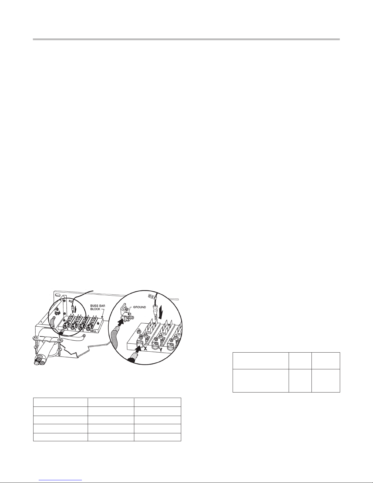
6. Terminate source end of cable or wire bundle: As
mentioned in item 2 (on page 6), the most common
cable termination is to break the ends out as pig-
tails and leave its hookup to the house electrician in
each venue. In some circumstances, a suitable con-
nector may be provided at the power source and the
cable can be terminated with a mating connector.
Often these will be Cam-Lok®or similar connectors
for each individual conductor.
If you want to provide a way to disconnect the cable
from the ASD-120 for separate storage or shipment,
one good way is to permanently attach a very short
cable to the ASD-120 and terminate it with Cam-Lok,
Meltric, or similar high-current connectors. A long
cable with mating Cam-Loks would then be prepared
which could easily be disconnected and stored. A
good source for custom made high power cables is
800-CAM-LOKS).
Table 4 on page 9.
CONTROLLING
ON/OFF
SEQUENCE:
ADVANCED
The quick start section at the front of the manual is adequate for
typical use. The following is an advanced tutorial and description
for those who are so inclined.
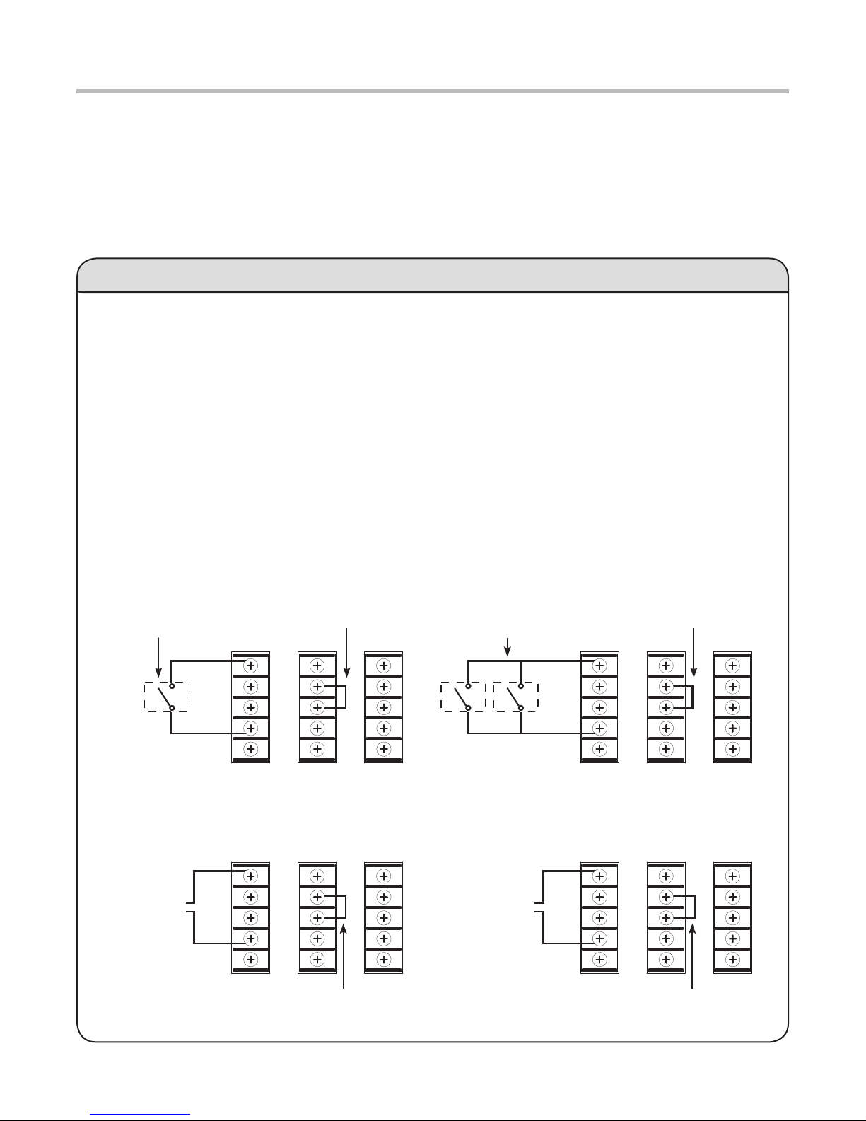
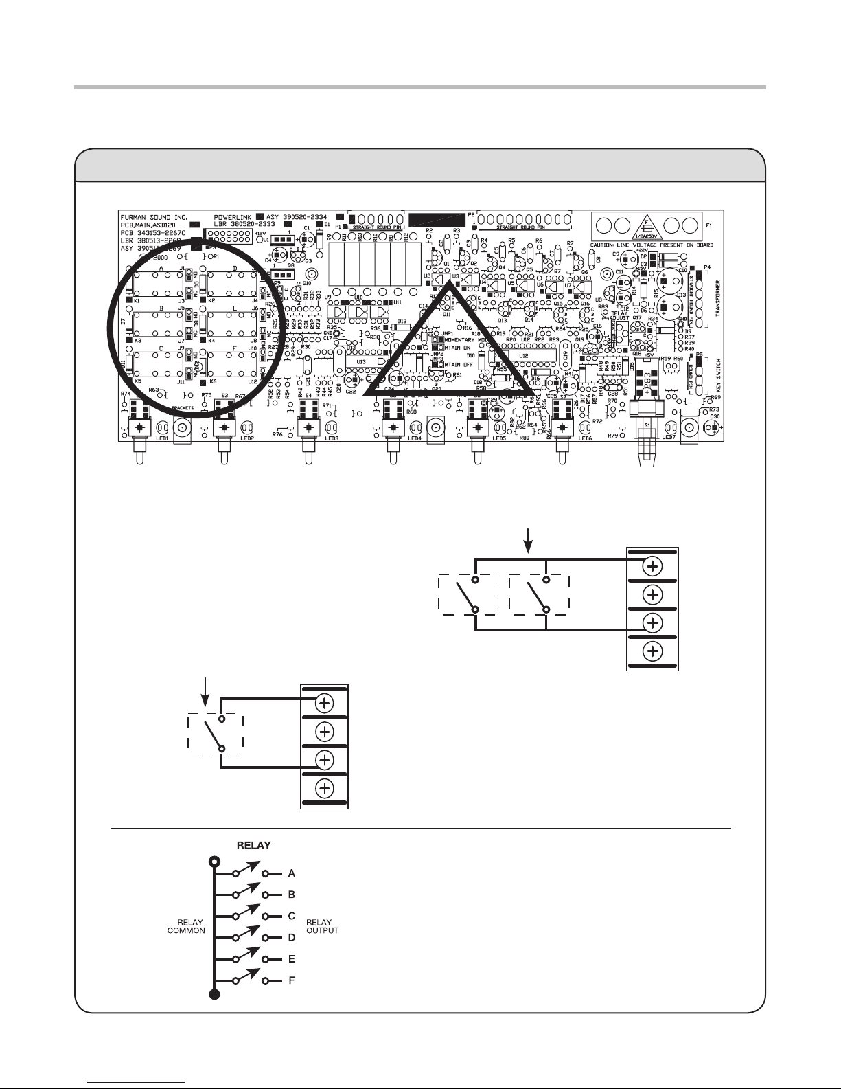
A normal, time-delayed on or off sequence may be
initiated in either of two ways: locally, via the front
panel key switch, or remotely, via a remotely located
maintained or momentary switch connected to the
behavior of any individual circuit may be overridden
switch.
in order from A to F when sequencing on, and turn
the outlets off in the reverse order from F to A when
sequencing off. The time for each step is internally
adjustable with a trim pot, with a range of 0.2 to > 12
seconds per step. (Total time for the entire sequence is
from 1 second to > 1 minute).
Local control: Turning the key to the ON (or possibly
that in the absence of any signal applied to the remote
input, the REM position defaults to on. (If the ASD-120
has been changed from the factory-preset Maintained
Mode to Momentary Mode, you must also press the
purely local control, you should leave the mode set to
Maintained.)
When the unit is turned on with the key switch, the
ASD-120 will stay on if all outlets are already on, or, if
all outlets are off, will begin turning on outlets starting
with outlet A, then B, etc. until all outlets are on. If the
unit was in the middle of sequencing off and had not
yet turned off all outlets, the lowest outlet that was
currently off will go on, so the sequence reverses
without ever deactivating the outlets that had not
yet gone off. The lowest off outlet turns on within 0.2
seconds, regardless of the setting of the delay time
trimpot. The next and all following outlets turn on at
intervals controlled by the trimpot. The factory default
setting is approximately 8 seconds per step.
When the unit is turned off with the key switch, the
ASD-120 will stay off if all outlets are already off, or, if
all outlets are on, will begin turning off outlets starting
with outlet F, then E, etc. until all outlets are off. If
the unit was in the middle of sequencing on and had
not yet turned on all outlets, the highest outlet that
is currently on will go off, so the sequence reverses
without ever activating the outlets that had not yet
turned on. The highest on outlet turns off within 0.2
seconds, regardless of the setting of the internal delay
time trimpot. The next and all following outlets turn off
at intervals controlled by the trimpot.
Remote Control: In the REM position, an on or
off sequence is initiated by one or more switches
connected to the rear panel inputs, or, in Momentary
button. The ASD-120 responds exactly as it does as
described in the preceding section on local control.
See the next section for a discussion of Remote
Operating Modes.
When the key is in either the ON or OFF position, the
rear panel remote control inputs. If the key switch is later
returned to the REM position, the signals supplied to the
rear panel remote inputs will again control the unit.
8

ASD-120 – SEQUENCED POWER DISTRO
Overriding a sequence: The ASD-120 outlets are
turned on and off by high power relays. The relays are
controlled by drivers that can be activated either by the
internal control circuits, or directly by a three-position
(one per outlet) can override the sequencing circuits,
and are intended as a secondary means of control to
allow individual on/off control of each outlet for diag-
nostic purposes. Following are the three positions of
regardless of state of sequence control circuits. Cen-
ter: Outlet is controlled by the sequence circuits (the
normal position). Down: Outlet is off regardless of state
of sequence control circuits. The center position is the
normal operating position, and allows control by the
sequencing circuits.
Signal relays: The ASD-120 also has six low level
signal relays, accessible by the rear panel terminals
labeled A through F, that are powered by the same
drive that turns on the AC power relays for the six
duplex outlets. These signal relays have an isolated
common (labeled RELAY COM) that is independent
of the chassis and signal grounds of the ASD-120, for
easy interfacing to virtually any other device that could
act as a slave to follow the ASD-120.
There is an internal jumper for each signal relay that
allows selection of the normally closed or normally
open contacts between each of the A to F terminals
and RELAY COM. The factory default is that the
contacts are closed when the associated outlet is off
(normally closed).
The relay contacts may be easily converted to normally
open operation by moving six “suitcase” jumpers on
the unit from AC power. Remove the four screws that
secure the top cover and the phillips screw on the
upper front panel. There are twelve small two-pin
connectors labeled J1 through J12, located near the
left side of the largest circuit board. Six of the twelve
are joined by small black suitcase jumpers. To change
the mode, gently pull them up and reposition them in
accordance with Table 4 on the left. Replace the top
cover and screws.
REMOTE
OPERATING
MODES
If the ASD-120 will be controlled locally only, you may
skip this section and the next section of the manual.
There are three remote operating modes available:
Maintained Mode/Normally On, which is the default,
Maintained Mode/Normally Off, and Momentary Mode.
The Momentary Mode on the ASD-120 shares the
same characteristics as the Momentary Mode on the
FORCE ON, FORCE OFF) are controlled by applying
REM COM terminal.
This is the default control logic on all of our existing
inputs are enhanced in the following ways: (1) They are
polarity independent, and work with positive, negative
or AC control signals. (2) They are optically isolated.
They safely accept up to 130 VAC, for direct control
from mains supply.
MAINTAINED MODE/
NORMALLY ON (DEFAULT)
In the absence of any signal applied to the remote
input, the ASD-120 will sequence on as soon as power
is applied, and the key switch is turned to REM or ON.
This is Maintained Mode/Normally On. In this mode,
voltage must be continually applied to the REM input
is in the REM position. This mode is compatible with all
Internal jumpers allow selection of either of two other
Table 4, Internal User Settable Jumpers.
JMP1 Momentary Mode
JMP2 Maintained Mode, Normally ON*
JMP3 Maintained Mode, Normally OFF
NOTE: Connect only one jumper of the JMP1-JMP3 group at a time.
J 1, 2, 5, Normally Open jumper positions for signal
6, 9,10 (low level) relays A, D, B, E, C, F respectively
J 3, 4, 7, Normally Closed jumper positions
8,11,12 for signal relays A, D, B, E, C, F respectively*
NOTE: Connect one set of six jumpers of the J1-J12 group at a time.
Table 4: Internal user settable jumpers
* Factory Default
9

ASD-120 – SEQUENCED POWER DISTRO
MAINTAINED MODE/
NORMALLY OFF
This mode is just the reverse of the Maintained Mode/
-
til voltage is applied to the REM input. Voltage must be
continually applied to keep the unit on, when the key
switch is in the REM position. This setting will be useful
to interface to other brands of controller that have posi-
tive control logic (i.e. they put out a signal to indicate
that attached gear should turn on). In addition, since
the REM inputs are optically isolated, and designed to
accept up to 130 VAC, this mode allows the ASD-120
to sequence on if some other source of AC line voltage
is turned on.
MOMENTARY MODE
only needs a momentary signal to change its state
after power is lost and reapplied for any reason) the
“memory” state is off. It will stay off until sequenced
push-button or a momentary connection of the REM
6 VAC (130V max). The sequence starts on the rising
edge of the signal. The rear panel +12V output may be
used as a trigger source. This is further explained in
the following section “Setup for Remote Operation”.
Once the ASD-120 is on (or is sequencing on), ap-
plying voltage momentarily to the REM input starts
switching the ASD-120 off, in descending sequence.
the front panel is effectively the same as applying
a signal to the REM input (although the actual con-
nection is applied to an internal node, not to the REM
terminal on the rear barrier strip).
In Momentary Mode there are two additional inputs
that are not required, but may be useful where multiple
SETUP
FOR REMOTE
OPERATION
The barrier terminal strip on the ASD-120 rear panel
allows a switch (or switches) to be connected to turn
the unit on and off at a distance, and provides vari-
ous power, status and relay closure outputs. In the
sequence. The switch may be either a momentary or
maintained-contact type. An LED may also be installed
at the remote end to indicate power is on, but will
require a third wire.
MOMENTARY VS. MAINTAINED
CONTACT SWITCHING
An on-off switch of either kind may be used to actuate
such as most toggle switches and push-on/push-off
button switches, and including the Furman RS-1 wall
mount key lock switch, are open until actuated, then
stay closed until actuated again. Momentary switches,
including the Furman RS-2 switch, are usually push-
button types that are normally open and stay closed
only as long as the button is pressed.
Maintained switches are generally most convenient
when there is only one remote location. When more
than one location is required, momentary switches
offer the advantage that either the turn-on or the turn-
off sequence may be started from any location.
The ASD-120 is shipped factory-set for maintained
operation. It may be easily converted to momentary
AC power. Remove the four screws that secure the
top cover and the phillips screw on the upper front
panel. There are three small two-pin connectors near
triangle on page 4). A small black suitcase jumper can
page 9 for jumper numbers and function description.)
MAINTAINED MODE/
NORMALLY ON
A simple connection of the REM terminal to the +12V
terminal initiates an OFF sequence. Disconnecting it
initiates an on sequence. If the cable run is long, it is
recommended that the REM wire be tied to the ASD-
conductor and a double-throw switch. NOTE: The REM
source. To use the +12V with the REM input, the
10

ASD-120 – SEQUENCED POWER DISTRO
REM COM terminal must be connected to the adjacent
ground terminal on the rear barrier block. In Maintained
button on the front panel. If you do press the button,
the ASD-120, if on, will start an off sequence that will
last only until you release the button.
MAINTAINED MODE/
NORMALLY OFF
A simple connection of the REM terminal to the +12V
terminal initiates an on sequence. Disconnecting it
initiates an off sequence. The other instructions are
identical to those in the Maintained Mode/Normally On
section above. Again, do not use the START ON/OFF
the button, the ASD-120, if off, will start an on se-
quence that will last only until you release the button.
MOMENTARY MODE
A momentary connection of the REM terminal to the
The +12V output on the rear barrier strip can be used to
trigger the REM input. As in Momentary mode, the REM
COM must be connected to the adjacent GND terminal.
This mode also requires only two wires in the simplest
case, +12V and REM. You may wire any number
of momentary switches in parallel. In this mode the
to trigger an up/down sequence.
In all models, the STATUS terminal is an output that
may be used to illuminate an LED at the remote
location to indicate that power is available at the ASD-
least in the process of sequencing on); if low, the unit
is off (or sequencing off). Simply connect the indicator
LED between STATUS and GND (a series resistor is
not required). If the LED does not light when the switch
is in the ON position, check the polarity and reverse
the LED leads if it is wrong. If a Furman RS-1 is the
department for the proper wiring diagrams. The
STATUS output is a 12V source, current limited to 10
mA. If you wish to use the STATUS output as a voltage
signal to some monitoring device, and also wish to
light a status LED on a remote panel, put a 1 K Ohm
1/4-watt resistor in series with the LED.
You can use more than one ASD-120 to handle loads
that exceed 120 amps. To control them remotely with
one or more remote switches, connect the REM and
REM COM terminals of all units together. You might
need to connect the +12V or GND terminals. Be sure
that the mode (momentary or maintained) of all units
is set the same. Connect a single maintained switch
or one or more momentary switches to the nearest
ASD-120, as discussed in the sections above. To avoid
tripping house breakers, the power input for each ASD-
120 should come from a separate service. If you are
unsure whether your building wiring can accommodate
electrician.
Because the trigger sources provided on the rear of
the ASD-120 (START and +12V) have a GND that
is isolated from the REM COM, it may be necessary
to connect GND to REM COM on all units. This will
usually be needed. The GND and REM COM would be
left isolated if the ASD-120(s) are to be signalled by
some other source of voltage, such as the AC line, or
a third party controller. The +12V output or the START
output on a single ASD-120 has enough output current
to switch dozens of REM inputs simultaneously,
however, it is harmless to parallel the +12V outputs.
momentary remote switches, they will all change state
(from on to off or vice versa) on each rising edge of
the local ASD-120 unless the START terminal on the
rear barrier strip of each unit is connected to the REM
terminal directly below it. To keep all units in sync,
please be sure to make this connection on all units.
Once the START and REM terminals are connected on
all units, any remote switch and any of the START ON/
panel will turn off (or on) any individual unit without
affecting the other units.
The STATUS lines work the same in either mode. Each
of its unit, and is affected by both the “memorized”
state and by the front panel key switch. A separate
LED must be used to indicate the status of each ASD-
switches. The STATUS output only indicates if the se-
quencing control circuits are set to on or off.
11

ASD-120 – SEQUENCED POWER DISTRO
STATUS output signal on the rear panel
allows remote indication of whether the
unit is on or off (high indicates the unit is on
or sequencing on, low that the ASD-120 is
off or sequencing off)
+12V output terminal on rear has 40 mA
capacity to power many external devices
+12V supply and STATUS terminals are true
voltage sources, with current limiting circuits
that prevent damage if the output is heavily
loaded or shorted. This allows direct connec-
tion of an LED to the STATUS output, or if a
voltage is desired from the STATUS output,
an external resistor in series with the LED
(at least 1K) will allow the STATUS output to
rise to 12 VDC while simultaneously lighting
the LED.
A START output on the rear goes to +12V
(with a 1K source impedance) when the
front panel momentary START ON/OFF SE-
the ASD-120 to send a signal to other units
that can be turned on and off by a momentary
voltage signal. Note: This start function is
merged with the REM input on other Furman
products.
following enhancements: A separate LED (next to the
labeled REM ON) shows the “memorized” state. This
LED will be on whenever the remote control circuits
are set to turn the unit on, off if the remote control
circuits are trying to turn the unit off. (Other Furman
products blink one of their status lights to indicate the
remote status.)
Because the remote control inputs are optically isolated,
they have a separate “ground” from the chassis and
control logic. In some cases this “ground,” labeled
REM COM, may need to be connected to the signal
ground GND. The ASD-120 has three remote input
terminals. The REM input is used in both Momentary
and Maintained modes, as described in the previous
sections on remote operating modes. FORCE ON and
FORCE OFF work only in momentary mode, and are
If the unit is off, applying power momentarily to the
FORCE ON input will set the memorized state to on,
which will start the on sequence. Applying further
control signals (of any duration) to this input will have
no effect. If the unit is on (or sequencing on) applying
power momentarily to the FORCE OFF input will
set the memorized state to off, which will start the
off sequence. Applying further control signals (any
duration) to this input has no effect.
FORCE ON/FORCE OFF
The FORCE ON and FORCE OFF inputs provide an
no possibility that the units will get out of sync with
each other, as can happen when using the regular
REM toggle input. These two inputs also make the
using the separate ON and OFF inputs instead of the
single REM toggle input is that two momentary switch-
12
To take care of the special (hopefully rare) case of hav-
of sync such that every time a remote button is pushed,
some units turn on and others turn off, there is a spe-
four seconds, or holding the REM line high for at least
4 seconds will force all units to the off state, which will
put them back in sync. This may be the only way to
re-sync units other than disconnecting AC power to all
the units. Remember — operating the front panel key
switch does not affect the stored state of the unit, even
ADDITIONAL
REMOTE
FEATURES:

ASD-120 – SEQUENCED POWER DISTRO
against defects or damages arising from improper
installation, against defects in products or components
not manufactured by Manufacturer, or against
damages resulting from such non-Manufacturer
made products or components. This warranty shall
be cancelable by Manufacturer at its sole discretion
authorization from Furman Sound. This warranty also
been affected or attempted by persons other than
pursuant to written authorization by Manufacturer.
THIS WARRANTY IS EXCLUSIVE. The sole and
exclusive obligation of Manufacturer shall be to repair
for the period provided above. Manufacturer shall not
or any part thereof, whether based on contract, tort,
strict liability or otherwise. Under no circumstances,
whether based on this Limited Warranty or otherwise,
shall Manufacturer be liable for incidental, special,
WRITTEN STATEMENTS DO NOT CONSTITUTE
and are not a part of the contract for sale or this limited
warranty. This Limited Warranty states the entire
If any part of this Limited Warranty is determined to be
void or illegal, the remainder shall remain in full force
and effect.
SERVICE
Before returning any equipment for repair, please
be sure that it is adequately packed and cushioned
against damage in shipment, and that it is insured. We
suggest that you save the original packaging and use it
to ship the product for servicing. Also, please enclose
a note giving your name, address, phone number and
a description of the problem. NOTE: All equipment
being returned for repair must have a Return Autho-
rization (RA) Number. To get an RA Number, please
the front of all packages.
13
es (and at least three wires) are required at every
remote control location.
Where a single ASD-120 is controlled from multiple
remote locations there is no advantage to using the
separate ON and OFF inputs, unless the switch loca-
is currently on or off.
LIMITED 3 YEAR
WARRANTEY
WARRANTY
Furman Sound, LLC., having its principal place of
free from defects in material and workmanship for a
period of three years from the date of purchase. The
the date of purchase to complete warranty registration
does not conform to this Limited Warranty during
claimed defects. If the defects are of such type and
nature as to be covered by this warranty, Manufacturer
Furman factory or to an authorized Furman repair
location. Warranty claims should be accompanied by
a copy of the original purchase invoice showing the
purchase date; this is not necessary if the Warranty
Registration was completed either via the mailed in
warranty card or on-line website registration. Shipping
charges to the Furman factory or to an authorized
the product. Manufacturer shall, at its own expense,
Manufacturer.
THE FOREGOING IS IN LIEU OF ALL OTHER
OF MERCHANTABILITY AND FITNESS FOR A
warrant against damages or defects arising out of

ASD-120 – SEQUENCED POWER DISTRO

ASD-120 – SEQUENCED POWER DISTRO
Furman Sound, LLC.
1690 Corporate Circle
Web: www.furmansound.com
E-mail: [email protected]
VOLTAGE AND CURRENT Input Current: 120 amps
Input Voltage: 120/240V single phase, or 208V 3-ph.
Output: Six identical 20 amp, 120V circuits
CIRCUIT BREAKERS Thermal, 20A
(adjustable with internal trimpot)
130 VAC from REM COM to chassis
max from relay common to chassis. Relay can switch 1/2 amp
Clamping Voltage: 200V peak.
Response Time: 1 nanosecond.
Maximum Spike Energy: 80 joules per circuit.
OTHER Mechanical: Weight: 20 lbs (9.1 kg).
Construction: Steel chassis, zinc chromate plating;
Safety Information: All current-carrying components
ASD-120 SPECIFICATIONS
101404-D
Other manuals for ASD-120
1
Table of contents
Other Furman Power Distribution Unit manuals
Popular Power Distribution Unit manuals by other brands

ETA Systems
ETA Systems PD11LV owner's manual

rollease acmeda
rollease acmeda AUTOMATE MT03-0301-411005 manual

ATEN
ATEN eco PDU PE7214 user manual

Grundfos
Grundfos MP 204 Installation and operating instructions

Transcension
Transcension HS2 Hybrid Distribution Splitter user manual

ATEN
ATEN NRGence PE Series user manual