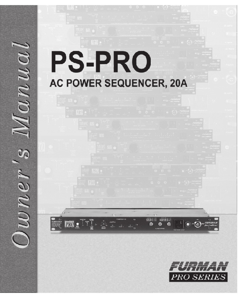
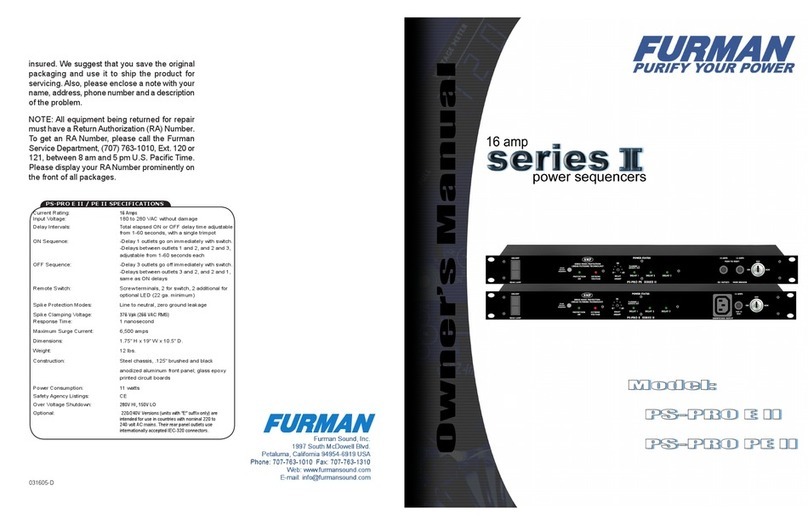
Furman PS-PRO User manual

Owner’s Manual
MODELSPS-PRO,PS-PROE
4-9937
© 1998 FURMAN SOUND, INC.
960111-1406
PRO SERIES
20 Amp Power
Conditioner/Sequencer
Other Furman Products
PowerConditioning&Distribution
PL-8, PL-PLUS Power Conditioner & Light Module, 15A
PL-PRO Power Conditioner & Light Module, 20A
PL-TUNER Power Conditioner/Instrument Tuner, 15A
PLH-15 Power and Light Center, 15A
PM-8 Power Conditioner/Monitor, 15A
PM-PRO Power Conditioner/Monitor, 20A
PS-8, PS-8R Power Conditioner/Sequencer, 15A
PowerLink Remote AC Power Sequence Controller
PowerPort Remote AC Power Controller
MiniPort-15 Power Relay, 15A
MiniPort-20 Power Relay, 20A
MiniPort-30 Power Relay, 30A
MiniPort-15Q Power Relay for Quad Box Mount, 15A
MiniPort-20Q Power Relay for Quad Box Mount, 20A
RS-1 SystemControlPanel,Maintained Switching
RS-2 System Control Panel, Momentary Switching
AR-1215 ACLine VoltageRegulator, 15A, 120V
AR-2306 AC Line Voltage Regulator, 6A, 230V
AR-1220 AC Line Voltage Regulator, 20A, 120/100V
AR-1230 AC Line Voltage Regulator, 30A, 120/100V
AR-2330 AC Line Voltage Regulator, 30A, 220/230/240V
AR-2330D AC Line Voltage Regulator, 30A, 240/230/220V
AR-PRO AC Line Voltage Regulator, 30A, 120V, Worldwide Use
ACD-100 Power Distro, 100A
ASD-120 Sequenced Power Distro, 120A
IT-1210 IsolationTransformer, Balanced AC Power, 10A
IT-1220 Isolation Transformer, Balanced AC Power, 20A
IT-1230 Isolation Transformer, Balanced AC Power, 30A
PlugLock™ Locking Outlet Strip
PGP-20, PGP-60 PlugLock-PRO Locking Outlet Systems, 20A, 60A
PGP-S Remote Power Switcher for PlugLock-PRO’s, 60A
Audio Signal Processing
PQ-3 Reissue Parametric Equalizer, Instrument Preamp
Q-151, Q-152 Dual 15-Band Graphic Equalizer
Q-301, Q-302 30-Band Graphic Equalizer
Q-602 Dual 30-Band Graphic Equalizer
PUNCH-10 Bass Enhancement System
X-312 12 dB Crossover
X-324 2-Way/3-Way 24 dB Crossover
X-424 3-Way/4,5-Way 24 dB Crossover
X-524 4-Way 24 dB Crossover
LC-6 StereoCompressor/Gate
SP-20A Stereo Half Rack Power Amp, 20W per channel
HA-6A Headphone/Monitor Amp
HR-2 Headphone Passive Remote Box
HDS-6 Headphone Distribution System
HR-6 Personal Headphone Mixer for use with HDS-6
PB-48 48-PointPatch Baywith TRS Connectors
PB-48D 48-Point Patch Bay with TRS and D-Sub Connectors
(Full range of patch cords also available)
MM-3 Three Input Mic Mixer
MM-8A 4 x 2 Rack-Mount Mixer
SM-3 Stereo Mixer with Ducking
IP-2, IP-2B Iso-Patch, Dual Isolator, 2 channel
SRM-80 Signal Router/Monitor
VU-40 System Monitor (Power/VU Meter)
SC-1, 2 SecurityCovers
PS-PRO 20-AMP POWER CONDITIONER/SEQUENCER
Please contact us by phone,
fax or e-mail for a free copy
of our latest color catalog.

PS-PRO SPECIFICATIONS
Currentrating: 20Amps(2400Wattsat120VAC)
Export(3600 watts at230 VAC)
InputVoltage: 85to264VACwithoutdamage
Exportseries(150to280VACPS-PROE)
Mains Wiring analyzer: Detectsonenormal mode andfivefault modes
NotapplicabletoPS-PROE
DelayIntervals: TotalelapsedONorOFFdelaytimeadjustable
from1-60seconds,withasingletrimpot:
ONsequence:Delay 1 outletsgoon immediately
withswitch.Delaysbetweenoutlets1and2,and2
and3,adjustable from1-30seconds each
OFFsequence:Delay 3 outletsgooff immediately
withswitch.Delaysbetweenoutlets3and2,and2
and1,sameasONdelays
RemoteSwitch: Screwterminals, 2for switch,1 additionalfor
optionalLED (22ga. minimum)
Spike Protection Modes: Lineto neutral,neutral to ground,line toground
ClampingVoltage, all modes: 200V peak (390 VAC peak PS-PROE)
Responsetime: 1nanosecond
Maximumsurgecurrent: 11,000amps(8x20mSpulse)
Maximum spike energy: 550 joules total
Noiseattenuation: Differentialmode:Greaterthan40dB;
Commonmode: greater than60 dB;
both1 to200 MHz
Dimensions: 1.75"Hx19"Wx10"D.
Weight: 6lbs (2.7 kg).
Construction: Steelchassis,zinc chromateplating;.125" brushed
andblackanodizedaluminumfrontpanel;glass
epoxyprintedcircuitboards.
PowerConsumption: 11watts
SafetyAgencyApprovals: UL,C-UL, CE listed.
Optional: 220/240VVersions(unitswith“E”suffixonly)are
intendedforuse in countrieswithnominal220 to
240voltACmains.Theirrearpaneloutletsuse
internationallyaccepted IEC-320C-13 connectors.
YourKeyNumber: ________________________________________
(WriteyourKeyNumberaboveforfuturereference)
TheFurman PS-PROis madein theU.S.A.
PS-PRO 20-AMP POWER CONDITIONER/SEQUENCER2
Furman Sound, Inc.
1997SouthMcDowellBlvd.
Petaluma, California 94954-6919
Phone: (707) 763-1010
Fax:(707)763-1310
e-mail:[email protected]
Web:www.furmansound.com
ThreeYearWarranty
TheFurmanPS-PROiswarrantedagainstfailuresduetodefectivepartsorfaulty
workmanship for a period of three years after delivery to the original owner. During
this period, Furman will make any necessary repairs without charge for parts or
labor.Shippingchargestothefactoryorrepairstationmustbeprepaidbytheowner;
returnshippingcharges (viaUPSGround)willbepaidbyFurman.
This warranty applies only to the original owner and is not transferable. Also, it
does not apply to repairs done other than by the Furman factory or Authorized Re-
pair Stations.
This warranty shall be cancelable by Furman at its sole discretion if the
PS-PROunithasbeensubjectedtophysicalabuseorhasbeenmodifiedinanyway
without written authorization from Furman. Furman’s liability under this
warranty is limited to repair or replacement of the defective unit.
Furman will not be responsible for incidental or consequential damages
resulting from the use or misuse of its products. Some states do not allow
theexclusionof incidental orconsequentialdamages, so the abovelimitationsmay
not apply to you. This warranty gives you specific legal rights, and you may
also have other rights which vary from state to state. Warranty claims should be
accompaniedbyacopyoftheoriginalpurchaseinvoiceshowingthepurchasedate
(if a Warranty Registration Card was mailed in at the time of purchase, this
is not necessary). Before returning any equipment for repair, please read the
importantinformationonservicebelow.
Service
Before returning any equipment for repair, please be sure that it is adequately
packed and cushioned against damage in shipment, and that it is insured. We sug-
gestthatyou savetheoriginalpackaginganduseittoshiptheproductforservicing.
Also, please enclose a note giving your name, address, phone number and a de-
scription of the problem.
NOTE: All equipment being returned for repair must have a Return
Authorization (RA) Number. To get an RA Number, please call the Furman Service
Department, (707) 763-1010, Ext. 40, between 8 am and 5 pm U.S. Pacific Time.
Pleasedisplayyour RA Numberprominentlyon the front ofallpackages.
PS-PRO 20-AMP POWER CONDITIONER/SEQUENCER 15

3
Introduction
Congratulations on your purchase of a Furman PS-PRO Power Conditioner/
Sequencer. The PS-PRO is one of Furman’s top-of-the-line PRO Series, offering
maximum protection from the AC line hazards faced by delicate analog and digital
proaudioandvideoequipment.
ThePS-PRO isapower sequencer,meaning itiscapable ofpoweringa rackfull
ofequipment inthree stepsseparated bytimed delays.Itisusefulwhenevervarious
kinds of equipment must be powered up or down in groups, rather than all simulta-
neously. In audio systems, sequenced powering is often necessary to allow turn-on
transients from low level amplifiers and processors to settle down before any power
ampsare turnedon, becausesimultaneouspowering wouldresult inaloud,annoy-
ing,andpotentiallydestructive“pop”reachingthespeakers.Andinanylargesystem
whose components present an inductive load to the AC line (including electric mo-
tors, power supplies, and power amplifiers of all kinds), sequenced
powering can avoid excessive inrush currents that can cause circuit breakers to trip
even though the steady-state currents are not excessive. Power sequencing is par-
ticularlysuited toapplicationswherelargeinstallationsmustbeswitchedby inexpe-
riencedpersonnel.
The PS-PRO is controlled by a front panel key-operated switch to provide
security from non-authorized users tampering with the system. The switch has three
positions:OFF,REM, and ON, allowingforlocal or remotecontrol.With remote con-
trol, one or more PS-PRO’s may be installed in remote locations with on/off control
andLEDmonitoringvialow-voltagecontrolwires.
Besidesitspower sequencingcapabilities,thePS-PROcontainsmanyothercon-
ditioning and protection features. Both aspects of its functioning will be
discussed in the next sections.
PS-PRO Features
l20 amp (2400 watt) rating handles even the largest amplifiers
lExport series (16 amps, 3600 watts)
lMultiplelevelsof protection componentscansafely absorb largevoltage
spikes and provide highly effective RF filtering — the most comprehensive
protectionavailableanywhere!
lExtremeVoltageShutdownguardsagainstcatastrophicallywrongvoltages
lPowerStatusLED’sindicatewhich outletgroups havepower
lMains Wiring indicators monitor wiring integrity, show Normal and five kinds of
faults (not applicable to PS-PROE)
lRemote operation allows turn-on and turn-off at a distance simply by connect-
ing a momentary or maintained-contact switch (and LED if desired)
lMultipleunitsmay be linked to handle highercurrentsand/or more than three
delaygroups
lThreeunswitchedoutlets (one front, two rear)
lTen foot 12 AWG heavy duty power cord Export series ten foot 1.5 mm x2line
cordwithSchukoplug
lThreeyear limitedwarranty
PS-PRO 20-AMP POWER CONDITIONER/SEQUENCERPS-PRO 20-AMP POWER CONDITIONER/SEQUENCER
14
EffectsofLightning
Lightning is a natural phenomenon of overwhelming force that represents the
most difficult circumstance faced by a power protection product. The degree of
protection a PS-PRO can offer depends on the intensity of the strike. If lightning
strikes a distant power line and causes a relatively small disturbance to reach your
location, the spike suppressors in the PS-PRO will absorb the excess voltage
invisibly and harmlessly. However, if lightning strikes the actual building where
the PS-PRO is installed (or somewhere very nearby), some damage may be
unavoidableduetotheextremelyhighvoltageandcurrentpresent.Ifthisdoesoccur,
most likely damage will be limited to the PS-PRO itself and will affect only certain
spike suppression components (called varistors or MOV’s.) In this “suicide” mode,
the PS-PRO may sustain minor damage but generally will protect all
equipment plugged into it from much more serious and costly damage as
long as that equipment is properly grounded. Proper grounding requires the use of
three-prong AC cords, and that the building’s outlets are actually grounded to earth
asspecified bythe NationalElectrical Code.This isnotnecessarilyapplicabletothe
PS-PROE as the IEC does not recognize the same electrical grounding standard.
Any PS-PRO known to have taken a direct lightning hit should be checked by a
qualified technician or the Furman factory to determine whether the MOV’s need
replacement. (If the PS-PRO’s PROTECTION OK indicator is not lit, there is
definitelysomedamage.Somespikesuppressioncapabilitymaystillbeavailableby
MOV Bank #2, but there is no guarantee of this.)
For optimum protection, you should not rely exclusively on the PS-PRO to
protectagainstadirectlightning hit.Thefirstlineof defenseagainstlightningshould
be a lightning arrestor installed on your building’s electrical service entrance. If your
building does not have one, contact your local power company or an electrical
contractortohave one installed.

4PS-PRO 20-AMP POWER CONDITIONER/SEQUENCER
PowerSequencingFeatures
ThePS-PROrearpanelprovidesoneunswitchedoutletpairandthreeswitched
outletpairs.TheswitchedoutletpairsarelabeledDelay1,Delay2,andDelay3.(The
other pair of outlets on the rear panel and an additional single outlet on the front
panelareunswitched.)
Here’s how the PS-PRO works: When an ON sequence is initiated, power is
immediately applied to the Delay 1 outlets. Power is then applied to Delay 2 and
Delay 3 outlets per the 1-60 second total delay setting you choose with the front
panelDelay Adjustcontrol.
Thescrewdriver-settableDelay Adjust controls the total delaytimebetween the
Delay 1 and Delay 3 outlets. For example, if the Delay Adjust control is set to 30
seconds, Delay 1 outlets will go on immediately, Delay 2 outlets will receive power
15 seconds after Delay 1 outlets, and Delay 3 outlets will receive power 15
seconds after Delay 2 outlets. Therefore the total delay time is 30 seconds.
The order is reversed on an OFF sequence. For example, when an OFF
sequence is initiated and the Delay Adjust control is set at 60 seconds, Delay 3
outlets lose power immediately, Delay 2 outlets lose power 30 seconds later and
Delay1outletslosepower 30 seconds after the Delay 2 outlets havebeenshutoff.
Thetotaldelay time is 60 seconds.
Intheevent of a power outage, ofcourseall equipment plugged into a PS-PRO
will lose power simultaneously. However, when power is restored, the delayed
outlet groups will again turn on in the usual delayed sequence if the unit is being
operated in maintained mode. If it is being operated in momentary mode, the
delayed outlet groups will remain OFF. Remote operation with maintained and mo-
mentaryswitchesis covered on pages 6-7.
Installation recommendations:Inaudio/videoinstallations, werecommendthat
power amps receive power last—plug them all into Delay 3 or divide them into two
groupsandplugonegroupthroughDelay2andtheotherthroughDelay3.Lowlevel
equipment such as mixers and signal processors should use Delay 1. Equipment
incorporating clocks or timers such as VCR’s, or equipment that must respond to
wireless remote actuation, should use the unswitched outlets. We
suggest keeping the front panel unswitched outlet free for equipment that is only in
usetemporarily.
TheoverallcapacityofthePS-PROis20amps(16amps PS-PROE).Thisrefers
tothecombinedsteady-statecurrentdrawnbyalldevicespluggedintoallofitsnine
outlets. If this combined current level exceeds the product’s maximum rated at any
time,thecircuitbreakerwilltrip,cuttingoffpowertoyourrack.Ifthisoccurs,youmust
reduce the load by unplugging one or more units from the PS-PRO. Then push the
gray button on the circuit breaker (on the front panel) down and in to reset it.
Although20 amps (16ampsPS-PROE) is anabsolute limit, thePS-PROseries
will allow you to come as close as possible to using the full rated current, because
with power sequencing, the risk of tripping the breaker is greatly reduced. This is
because the PS-PRO handles large but temporary inrush currents in stages, rather
than simultaneously, allowing each stage to settle to its steady-state current draw
beforethe next stageispowered.
Outlets and Plugs: The PS-PRO’s four rear panel outlet pairs are
standard120V,20Aduplextypes(unlessorangeisolated-ground“SuperSpec”out-
lets have been substituted by special order.) The PS-PROE comes standard with
IEC 16 amp AC receptacles. These outlets are widely spaced, to
PS-PRO 20-AMP POWER CONDITIONER/SEQUENCER 13
Symptom: The PROTECTION OK indicator is not lit after the ON delay
haselapsed.
PossibleCause: Protectiondeviceshavebeendamaged.
ActionNeeded: Factory service.
Symptom: The GROUND OK indicator is not lit (not applicable to
PS-PROE).
PossibleCause: Nobuilding ground,or abadoutlet.
ActionNeeded: Locatea goodground, rungroundwire.
Symptom: TheEXTREME VOLTAGE Indicatorisflashing.
PossibleCause: Inputvoltage isbelow 80or above140 volts,causing power
to PS-PRO’s outlets to be shut down. (Input voltage is
below 150 or above 280 volts for PS-PROE.)
ActionNeeded: Correct line voltage. Consider installing a Furman AC line
voltageregulator.
Troubleshooting
The “ground ok” feature is not applicable to the PS-PROE.

accommodate one bulky plug-mounted “wall wart” power supply in each without
covering up an adjacent outlet. The front panel outlet is limited to 15 amp
use. The PS-PRO also uses a 20 amp line cord, which can be recognized by the
perpendicular blades on the plug. In 20 amp products, use of a plug of this type is
required for UL safety certification. It is compatible with 20 amp outlets (such as the
onesonthePS-PRO’srearpanel.)Formoreinformationabout20ampplugs,seethe
informationsheet“WhatKindOfPlugIsThis,Anyway?”thataccompaniedthismanual,
or request a copy from Furman. It may also be seen at our web site at
www.furmansound.com/whatkind.html. (PS-PROE:frontpaneloutletrating16amps,
AC cord is a SCHUKO-type.)
PowerConditioningFeatures
The PS-PRO provides a very high degree of power conditioning protection for
your expensive and delicate equipment. What sets Furman’s top-of-the-line
PRO-level protection apart from that offered by other conditioners is the quantity,
quality,and configurationofitssuppressiondevices.TheseincludeMOV’s,gas dis-
chargetubes,fast-blowfuses,andhighvoltageinductorsandcapacitors.Thisunique
combination can safely absorb and dissipate large spikes from nearby
lightning strikes and other sources (up to 11,000 amps across any wiring mode —
line-neutral,line-ground, orneutral-ground), aswell ashighly attenuateaudible high
frequency noise. Clean, filtered power is provided at all 9 outlets, even the
unswitchedones.
ThePS-PROalsoincludesspecialcircuitrytodetectadditionalwiringfaults,with
several front panel LED status indicators. The PS-PRO will even keep itself from
turning on, or will shut down under extreme conditions, if the voltage falls below 80
voltsorrisesabove140volts.Thisfeatureiscalled"ExtremeVoltageShutdown.”Itis
particularly valuable in the entertainment industry, where equipment is frequently
moved to different venues, and accidental connection to 220V (310Vfor PS-PROE)
is a real possibility. See pages 8-9 for more information on the various protection
features’indicatorlights.
Despiteitsmanyprotectivefeatures,youshouldbeawarethatthePS-PROdoes
notcompensateiftheAClinevoltageitselfishighorlow(i.e.,itdoesnotcompensate
forbrownoutconditions).Ifyoufrequentlymoveyourracktodifferentlocations,derive
powerfromgenerators, use long extension cords, travelinternationally,or are in an
areaparticularlypronetobrownouts,youmaybenefitfromtheuseofoneofFurman’s
ACLine VoltageRegulators inadditionto thePS-PRO. Ifyoudousea voltageregu-
lator, run the raw power line into the regulator first so that the PS-PRO receives a
stabilized voltage to distribute.
5
MainsWiringFaultAnalyzer
The PS-PRO also assists in analyzing any faults that may occur in the
AC mains wiring. Two green and one red neon indicators light in a specific
pattern for normal wiring and in different patterns for various faults. When the AC
wiring is correct, both green indicators will be lit, but not the red indicator. If any
other pattern of indicators is lit, a fault is present. The chart next to the indicators
PS-PRO 20-AMP POWER CONDITIONER/SEQUENCER
12 PS-PRO 20-AMP POWER CONDITIONER/SEQUENCER
To take care of special (hopefully rare) case of having several PS-PRO’s in
parallel that somehow get out of synch such that every time a remote button is
pushed,some units turn on and others turn off, there is a special feature of the
remotesignalline:
Holdingthe REMline highfor atleast 4seconds (whetherbyanactualremote
switch or by any unit’s START ON-OFF SEQUENCE switch) will force all units to
the OFF state, which will put them back in sync. This is the only way to re-sync
unitsotherthandisconnectingACpowertoalltheunits.Remember —turningany
key lock switch to OFF does not affect the stored state, even though it will
temporarilyturn the outputsof thatunitoff. Ifitis turnedbackto REM,that PS-PRO
will sequence back to ON because the stored state is still ON.
The above covers the case of multiple units in parallel (all sequences initiate
simultaneously). See “AC Relay Accessory PS-REL” below for a discussion of
wiringmultipleunitsinseries.
ACRelayAccessoryPS-REL
TheFurmanPS-RELACRelayAccessoryisasensorwhichcanthrowaswitch
inresponsetothepresenceof120VAC power,whileonly drawingaminimalamount
of that power. It is necessary whenever a PS-PRO must be turned on in response
to energizing a switched outlet, where that outlet is rated less than
20 amps or is not grounded. This occurs frequently in home theater installations
whenasmallungroundedswitchedoutletonapreamporreceiver(oftenactivated
by a wireless remote device) is to be used to power up a large amount of
equipment. The AC Relay Accessory may also be used to allow a PS-PRO to be
hookedupinseriesto anotherpowersequencertodouble thenumberofdelayed
turn-on/turn-off groups, by having the relay sense the presence of power at the
DELAY3outlet of the first sequencer.
ThePS-REL issimply asmallbox containinga double-throwrelay.Aterminal
stripprovidesaccesstothethreerelaycontacts:common(C),normally-open(NO),
andnormally-closed (NC).A two-prongAC plugon a6 footcordactivatestherelay
coil. The NC and C terminals should be connected to the +12V and REM IN
terminalsofthePS-PROrespectively. Ifthe distancebetweenthePS-RELandthe
PS-PROislong,the(NO)contactshouldalsobeconnectedtothePS-PRO’sground
lug.ThePS-REL’s ACplugshouldbeintheoutlettobesensed.ThePS-PROitself
should be plugged into a separate 20 amp electrical circuit. When AC power
appearsat thesensed outlet,the PS-PROwill beginitsturn-onsequenceandwill
be able to supply its full rated 20 amps.
FlashingDELAY 1 Indicator
The DELAY 1 LED on a PS-PRO flashes to indicate that a remote switch is
off or not connected. In Maintained Mode, this will only occur when the REM IN
terminal is tied to +12V. In Momentary Mode, the LED flashes if the stored state is
OFF. Since the flashing function is only concerned with the state of the remote
switch(es), note that it is possible for this LED to flash even when the unit is ON.
Thiscould occur whenthePS-PRO isunderlocal control(thekey lock switchis in
the ON position.) In this case, DELAY 1 would flash and DELAY 2 and DELAY 3
would be steadily lit. This occurrence serves as a warning that the unit will
sequence OFF if the key is turned to the REM position.
NOTE: The PS-PRO requires that a safety ground be present for proper
operation. Any attempt to operate the PS-PRO without a safety ground is
consideredimproperoperationandcouldinvalidatethewarranty.

The “memory” is independent of the key lock switch. This means that even if the
unit is sequenced off by turning the key lock switch to OFF, when the key
lock switch is turned back to REM the unit will sequence back on — it will not be
necessary to push the START ON-OFF SEQUENCE button again. The unit
“remembers” its state until the incoming power is lost, in which case it would default
back to OFF.
Thefront-panel keylock switchis notthe primarymeansofcontrolinmomentary
mode, and should normally be left in REM. It may be a useful secondary means of
control in the rare case of having several PS-PRO’s in parallel, if there is some rea-
son to shut down one unit without affecting the others.
Because it is a maintained-contact switch, the RS-1 is not an appropriate
remote switch for the PS-PRO when it is in momentary mode. The Furman RS-2 is
the proper choice. Please contact Furman for RS-2 wiring diagrams.
MultipleUnits
You can use more than one PS-PRO to handle loads that exceed 20 amps (16
amps PRO-E).To control them remotelywithone or more remoteswitches,connect
the REM IN terminals of all units together. Do not connect the +12V or GND termi-
nals. Be sure that the mode (momentary or maintained) of all units is set the same.
Setallkeylock switchestoREM.Connectasinglemaintainedswitchoroneormore
momentaryswitches tothe nearestPS-PRO,as discussedin thesectionsabove.To
avoidtrippinghousebreakers,thepowerinputforeachPS-PROshouldcomefroma
separate 20 amp AC circuit. If you are unsure whether your building wiring can ac-
commodatemultiplefully-loadedPS-PRO’sorPS-PRO’s,consultaqualifiedelectri-
cian.
If multiple PS-PRO’s are controlled by one or more momentary remote
switches, all the PS-PRO’s will change state (from on to off or vice versa) on each
rising edge of the voltage on the REM IN terminal. Any remote switch or any of the
STARTON-OFFSEQUENCEpushbuttonson anyunit’s frontpanelwilltoggleallthe
units.The key lockswitcheson eachunit’sfront panelwillturn off anyindividual unit
that is currently on, without affecting the other units.
The STATUS lines work the same in either mode. Each reflects the true state of
the outlets of its unit, and is affected by both the “memorized” state and by the key
lock switch. A separate LED must be used to indicate the status of each PS-PRO.
6PS-PRO 20-AMP POWER CONDITIONER/SEQUENCER
identifies the fault’s exact nature. Since any wiring fault presents a potentially
serioussafetyhazard,theassistanceofaqualifiedelectricianshouldbeobtainedin
correctingtheproblem.
ONor OFFSequencing
Themethod ofinitiating anON orOFF sequencedepends onwhethertheunitis
to be controlled locally or remotely. If remotely, it further depends on the type of
switch or switches used (momentary or maintained).
LocalControl
Forlocalcontrol,anONsequenceisinitiatedbyturningthekeyswitchtotheON
position,andanOFFsequence,byturningittotheREMorOFFposition.TheSTART
ON-OFFSEQUENCEpushbutton is notnormallyused in localoperation.
RemoteControl
WhenthePS-PRO’sfrontpanelkeylockswitchis inthe REMposition, itmaybe
controlled by one or more switches in remote locations. In the most basic
configuration, only two Class 1 wires and an SPST switch are needed to initiate an
ONorOFFsequence.Theswitchmaybeeitheramomentary-ormaintained-contact
type,dependingonajumpersettinginsidethePS-PRO.Ifanadditionalwireisused,
an LED may also be installed at the remote end to indicate that the power is on.
Momentaryvs.MaintainedContactSwitching
An on-off switch of either kind may be used to actuate the PS-PRO’s
remote operation. Maintained switches, such as most toggle switches and
push-on/push-off button switches, and including the Furman RS-1 key lock switch,
stay open until thrown, then stay closed until thrown again. Momentary switches,
usually pushbutton types like the Furman RS-2 (which also provides a locking key
switch), are normally open and stay closed only as long as the button is pressed.
Maintained switches are generally most convenient when there is only one re-
mote location. When more than one location is required, momentary switches offer
the advantage that either the turn-on or the turn-off sequence may be started from
any location.
PS-PRO units come factory-set for maintained operation. They may be easily
convertedtomomentary operation bymovinga jumper plug onthePS-PRO’s
NOTE:IfthePS-PROistobeusedunder localcontrol onlyand noswitchis
connected to the PS-PRO’s terminal strip, a jumper should be connected
betweenthe REMINand+12Vterminals.Otherwise,turningthefront panel
key switch to the REM position will turn the PS-PRO on.
MomentaryMode Continuedfrompage7
MomentaryModeRemote SwitchWiringDiagram
11PS-PRO 20-AMP POWER CONDITIONER/SEQUENCER

circuit board. To do this, first disconnect the unit from AC power. Remove the four
screwsthat securethetop cover.Just totheright ofthe centerofthe circuitboard (as
viewedfromthefront oftheunit),therearetwopairsofterminals,onelabeled“MAIN-
TAINED” and the other “MOMENTARY.” There will be a small black
“suitcase” jumper linking the MAINTAINED terminals. Slide it up and off, and
replaceit securely overtheMOMENTARY terminals.Reattachthe topcover.
MaintainedMode
AsimpleconnectionoftheREMINterminal tothe+12V terminalinitiatesanOFF
sequence. Disconnecting it initiates an ON sequence. If the cable run is long, it is
recommended that the REM IN terminal be tied to the PS-PRO’s GND terminal dur-
ing ON operation rather than leaving it floating. This will require the use of a third
conductorandadouble-throwswitch.Seethediagrambelow.
The STATUS terminal is an output that may be used to illuminate an LED at the
remotelocationtoindicatethatpowerisavailableatthePS-PRO’soutlets.Ifitishigh
(+5V), the unit is ON (or at least in the process of sequencing ON); if low, the unit is
OFF (or sequencing OFF). Simply connect the indicator LED between
STATUSandground (donotuse aseriesresistor). IftheLEDdoesnotlightwhenthe
switch is in the ON position, check the polarity and reverse the LED leads if it is
wrong. If a Furman RS-1 is the controlling switch, contact Furman’s Tech Support
departmentforthe properwiringdiagrams.
In Maintained Mode, DO NOT USE the “START ON-OFF SEQUENCE”
switch on the front panel. If you do, you may activate an unintended partial
turn-offsequence.
Momentary Mode
In Momentary Mode, the PS-PRO has “memory” — it only needs a momentary
signalfromthe remoteswitchtochangeitsstatefromONtoOFF.Whenfirstplugged
in(orafterpowerislostandreappliedforanyreason)thestoredstateisOFF,andthe
DELAY 1 LED will flash. The unit will stay off until sequenced on by a momentary
connection of the REM IN terminal to +12V (the key switch must be in the REM
position.) The sequence starts on the rising edge of the signal.
ThefrontpanelSTARTON-OFF SEQUENCEswitch isinparallelwith,andfunc-
tionally equivalent to, one or more remote momentary switches that may be con-
nected to the terminal strip in the rear.
MaintainedModeRemoteSwitchWiringDiagram
7PS-PRO 20-AMP POWER CONDITIONER/SEQUENCER
10 PS-PRO 20-AMP POWER CONDITIONER/SEQUENCER
Rear Panel
UNSWITCHED OUTLETS:ThePS-PRO rearpanelprovidesclean,filtered powerto
this pair of unswitched outlets, adjacent to the power cord.
SWITCHED (DELAYED) OUTLETS: The PS-PRO rear panel provides three
pairs of switched outlets, widely spaced to allow use of equipment with plug- in
(wallwart)transformers.TheseswitchedoutletpairsarelabeledDelay1,Delay2
andDelay3. After the frontpanelswitch is thrown toON,Delay 1 outlets receive
power instantly, Delay 2 outlets receive power 1-30 seconds later and Delay 3
outlets receive power 1-30 seconds after Delay 2 outlets are powered. When
thrown to OFF, the sequence is reversed, with Delay 3 losing power
instantly, Delay 2 outlets losing power 1-30 seconds later and Delay 1 outlets
losing power 1-30 seconds after Delay 2 outlets are shut down. The delay
intervalsmaybealteredwiththescrewdriver-adjustable DelayAdjustcontrolon
thefrontpanel.
TERMINAL STRIP: Allows one or more switches to be connected to turn the
PS-PROonandofffrom aremotelocation.Two,and sometimesthree,wiresare
needed to install a remote switch (see “Maintained Mode”, page 6.) If a
four-conductorcableis used, anLED may beinstalledat the remoteendto indi-
cate that the power is on.
Note: “The switch” referred to in this chart is either the front panel key lock switch
or, if used, a remote switch connected to the terminal strip of a PS-PRO.
This pair of outlets
goes off approx.
1/2 second after
the switch is
turned off.
Delay 3
This pair of outlets
comes on approx.
10 seconds after
the switch is
turned on.
POWER UP:
Same as above.
Unswitched
This pair of
outlets plus the
one on the
front panel are
on regardless
of the switch
position.
This pair of outlets
goes off approx.
10 seconds after
the switch is
turned off.
Delay 1
This pair of outlets
comes on approx.
1/2 second after
the switch is
turned on.
This pair of outlets
goes off approx.
5 seconds after
the switch is
turned off.
Delay 2
This pair of outlets
comes on approx.
5 seconds after
the switch is
turned on.
POWER DOWN:

8PS-PRO 20-AMP POWER CONDITIONER/SEQUENCER
START ON/OFF SEQUENCE: This pushbutton switch is used only when the key
lock switch is in REM position and the PS-PRO is in Momentary Mode. It then
acts the same as any other remote momentary switch that may be connected to
the rear panel terminal strip. If the switched outlets are on, pushing it begins an
OFFsequence.Ifthey areoff,pushingitbeginsanONsequence.Donotusethis
switchwheninMaintainedMode.
PROTECTIONOK:ThisLEDisnormallyonwhenthepowertothePS-PRO’soutlets
isswitched on.It monitorsthe integrityof theprotection devicesandreportsifthe
protection is compromised. If an extremely large spike is encountered that ex-
ceeds the PS-PRO’s capacity, the main group of input protectors will blow an
internalfuse,causing the indicator to go out.Ifthis LED is not lit whenthepower
switchison,fullprotection isnotfunctioning.Spikeprotection maystillexist,but
will have a reduced capacity to absorb current. If this LED is not lit, please con-
tact the Furman Service Department.
GROUND OK: This LED is normally on when the power to the PS-PRO’s outlets is
switchedon.Itmonitorsthe integrity of the grounding, and reports if the ground-
ing is compromised. It lights if a reasonably good safety ground exists. If this
indicator is not lit when the power is on, the PS-PRO is not properly grounded.
Unplug the PS-PRO and correct the ground. (Not applicable to PS-PROE.)
EXTREMEVOLTAGESHUTDOWN: This LED indicator is normally off. It monitors a
hazardcommonintheentertainmentindustry—wiringfaults—forexample,acci-
dentalconnectionto220V(inexcessof 310VforPS-PROE).ThePS-PROsenses
voltagesthataresohighorlowthat operationwouldbe impossible(under80Vor
over140V,under 150V or over280VPS-PROE) and shutsthepower down be-
foredamagecanoccur.Uponinitially applyingpowertothePS-PRO,thisindica-
tor will be lit if the unit is receiving below 80 volts or more than 140 volts, and
powerwillnot be applied to the PS-PRO’soutlets.If the unit has been operating
withanacceptableinputvoltageandthenthevoltagegoesoutoftheacceptable
range, the PS-PRO will shut down power to all of its switched outlets simulta-
neously,withoutobservingtheOFFdelaycycle,andthisLEDwillbeginflashing.
Whenpowerreturnstowithintheacceptablerange,thePS-PROwillobserveits
ON delays as it returns power to its switched outlets, and this LED will go out.
9PS-PRO 20-AMP POWER CONDITIONER/SEQUENCER
DELAY ADJUST:Thisscrewdriver-adjustabletrimpotallowsyoutosetthetotalturn-
on/turn-off delay time from 1 to 60 seconds, as explained on page 4. The trimpot
adjusts both the on delay and off delay times simultaneously. Turn the trimpot
clockwise to increase the on and off delay times; turn the trimpot
counterclockwise to decrease the delay times.
POWER STATUS (DELAY) LEDs: One green LED is provided for each of the three
delaystages.EachLEDlightswhenpowerisappliedtoitscorrespondingduplex
outlet on the rear panel. All three LEDs then remain steadily lit until power is
removed.Duringthe power-down delay cycle,eachLED goes offaspower to its
correspondingoutletisremoved.Inaddition,theDelay1LEDflashes ifaremote
switch (or the stored state) is OFF.
MAINSWIRINGINDICATORS:The PS-PROassists inanalyzinganyfaultsthat may
occurintheACmainswiring.Threeneonindicators(twogreenandonered)light
in a specific pattern for normal wiring and in different patterns for various faults.
WhentheACwiringis correct,both greenindicatorswillbelit.Ifa faultispresent,
thechartimmediatelyabovetheneonindicatorwillidentifytheexact natureofthe
fault. Since any wiring fault presents a potentially serious safety hazard, the as-
sistance of a qualified electrician should be obtained in correcting the problem.
(Not applicable to PS-PROE.)
NOTE: The Mains Wiring indicators and status LEDs stay on even when the power
switchis off.This featureallows youto checkthe mainswiringbeforepoweringup
yourequipment.These indicatorsaredesignedforcontinuous,ongoinguse.Like
a clock, they consume very little power.
UNSWITCHED OUTLET:Thisconvenientoutletprovidespoweratalltimeswhenthe
PS-PROispluggedinandoperatingundernormalpowerconditions.
ON/REM/OFF SWITCH: When turned to the ON position, this key lock switch
initiatesanONsequence,applyingpowertothePS-PRO’sswitchedoutlets.When
turned to the OFF position, it begins an OFF sequence. In the REM position, the
PS-PRO will accept on/off commands from a remote switch or switches that may
be connected to the rear panel terminals.
CIRCUIT BREAKER:The overall capacityof the PS-PROis 20 amps.(16ampsPS-
PROE).Ifthecombinedsteady-statecurrentdrawn byalldevicespluggedintoall
of its nine outlets level exceeds 20 amps at any time, the circuit breaker will trip,
cuttingoffpowertoyour rack. If this occurs, you must reduce theloadbyunplug-
ging one or more units from the PS-PRO, and reset it. You can reset the circuit
breaker by simply pressing in the button, which pops out when tripped.
However,becauseit isathermaltype,youmayhavetowaitafewmomentsafter
it trips for it to cool down before it will allow you to reset it.
Front Panel
NOTE: If the mains power is below 80 volts and has caused the PS-PRO to remove
power from its outlets, the PS-PRO will not restore power to its outlets until the
mains voltage is more than 90 volts (150 volts PS-PROE). If the mains power is
above 140 volts and has caused the PS-PRO to remove power from its outlets, the
PS-PRO will not restore power to its outlets until the mains voltage is less than 130
volts (270 volts PS-PROE). The reason for this is to prevent the power oscillating on
Some features and descripters not applicable to PS-PROE.
Other manuals for PS-PRO
1
This manual suits for next models
1
Table of contents
Other Furman Recording Equipment manuals

Furman
Furman MP-30 User manual

Furman
Furman RR-131 User manual

Furman
Furman PS-PRO E II User manual

Furman
Furman RackRider RR-131 User manual

Furman
Furman MP-15 User manual

Furman
Furman PS-PRO User manual

Furman
Furman PS8 R II User manual

Furman
Furman PWRLINK User manual

Furman
Furman PS-8R II User manual

Furman
Furman CN-1800S User manual