Furman PWRLINK User manual

REMOTE AC POWER
SEQUENCE CONTROLLER
PowerLink
AC POWER
SEQUENCING

POWERLINK REMOTE AC POWER SEQUENCE CONTROLLER
QUICK START
The illustrations below show several of the most common hookup methods for the PowerLink. There
are many other methods and features, however, so please refer to the rest of this manual for more
details if necessary.
For single unit operation with turn on from local or one remote location.
Default is maintained contact closure.
A
FORCE
OFF FEDCB
COM
GNDREM
COM
FORCE
ONREM
START
STATUS
+12V
ON
OFF
LATCHING (MAINTAINED)
REMOTE SWITCH
B
+12V E
COM
FORCE
OFF
GND F
REM
COM D
FORCE
ON
REM C
START A
STATUS
MOMENTARY
REMOTE SWITCHES
Multiple remote switches require use of Momentary Mode. Open the unit and move suitcase jumper
from JMP2 to JMP1.
A
FORCE
OFF FEDCB
COM
GNDREM
COM
FORCE
ONREM
START
STATUS
+12V
ON
OFF
LATCHING (MAINTAINED)
REMOTE SWITCH
B
+12V E
COM
FORCE
OFF
GND F
REM
COM D
FORCE
ON
REM C
START A
STATUS
MOMENTARY
REMOTE SWITCHES
1

POWERLINK REMOTE AC POWER SEQUENCE CONTROLLER
INTRODUCTION
Congratulations on your purchase
of a Furman PowerLink Remote AC Sequence
Controller.
Please read this manual completely before
installing your PowerLink.
FEATURES
Allows you to trigger six power con-
trol devices in a sequenced fashion
Six circuits, each with a front panel
status indicator
Circuits can be powered up and
down in sequence
Three position switch allows each cir-
cuit to be part of the sequencing, or
to be switched on/off independently
Six low level relays provide contact
closure (or opening) to control and
sequence other units, such as add-
itional PowerLinks, Furman Power-
Ports, MiniPorts, ASD-120 Sequenced
Power Distros and the PS-8R and
PS-PRO Power Sequencers
Sequence timing can be initiated from
unit or remotely using low voltage
control wires
Front panel key switch for security
Compact single rack space package
Three unswitched AC circuits – two
on the rear, one on the front
2

POWERLINK REMOTE AC POWER SEQUENCE CONTROLLER
DESCRIPTION
The Furman PowerLink is a compact, low-cost
rackmount Remote Sequencer that provides
timing for up to six power control devices, turning
them on and off in a preset seq uence. The delay
interval between the turn-on or turn-off of each
device and the next in sequence is user-
adjustable via an internal trimpot.
PowerLink can work with a group of relay-con-
trolled circuits such as Furman MiniPorts, to
create a very exible power control system that
can expand to handle as many circuits carrying
as much current as needed.
An on or off sequence can be initiated from the
PowerLink itself, using the built-in high-security lock-
ing key switch, or, if the key switch is set to enable
Remote operation, by one or more momentary or
maintained-action switches in distant locations.
The outputs of the PowerLink are low power relay
contacts, accessible through rear-panel screw
terminal strips. Outputs may be congured to
be normally-closed or normally-open by internal
jumpers. All input and output commons are
electrically isolated to avoid the creation of ground
loops.
Power sequencing is needed whenever various
kinds of equipment must be powered up or down
in groups, rather than all simultaneously. In audio
systems, sequenced powering is often necessary
to allow turn-on transients from low level pream-
pliers and processors to settle down before any
power amps are turned on. This is because
simultaneous powering can result in a loud, an-
noying, and potentially destructive “pop” reaching
the speakers. In any large system whose com-
ponents present an inductive load to the AC line
(including electric motors, power supplies, and
power ampliers of all kinds), sequenced power-
ing can avoid excessive inrush currents that can
cause circuit breakers to trip even though the
steady-state currents are not excessive.
The PowerLink’s front panel provides a three-
position switch for each control output that al-
lows each control output to be part of the power
up/down sequence, or to remain on or off apart
from the sequence. It also provides an LED that
indicates when the circuit in on.
The outputs of the PowerLink are low power relay
contacts, which can control Furman PowerPorts,
MiniPorts, PS-PRO and PS-8R Power Sequenc-
ers, or any other circuits that need to know when
a particular time delay has elapsed. In larger
systems, one or more additional PowerLinks can
be installed in remote locations and operated via
low-voltage control wiring, providing the capability
of controlling power sequencing for a system of
any size.
CONTROLLING ON/OFF
SEQUENCE
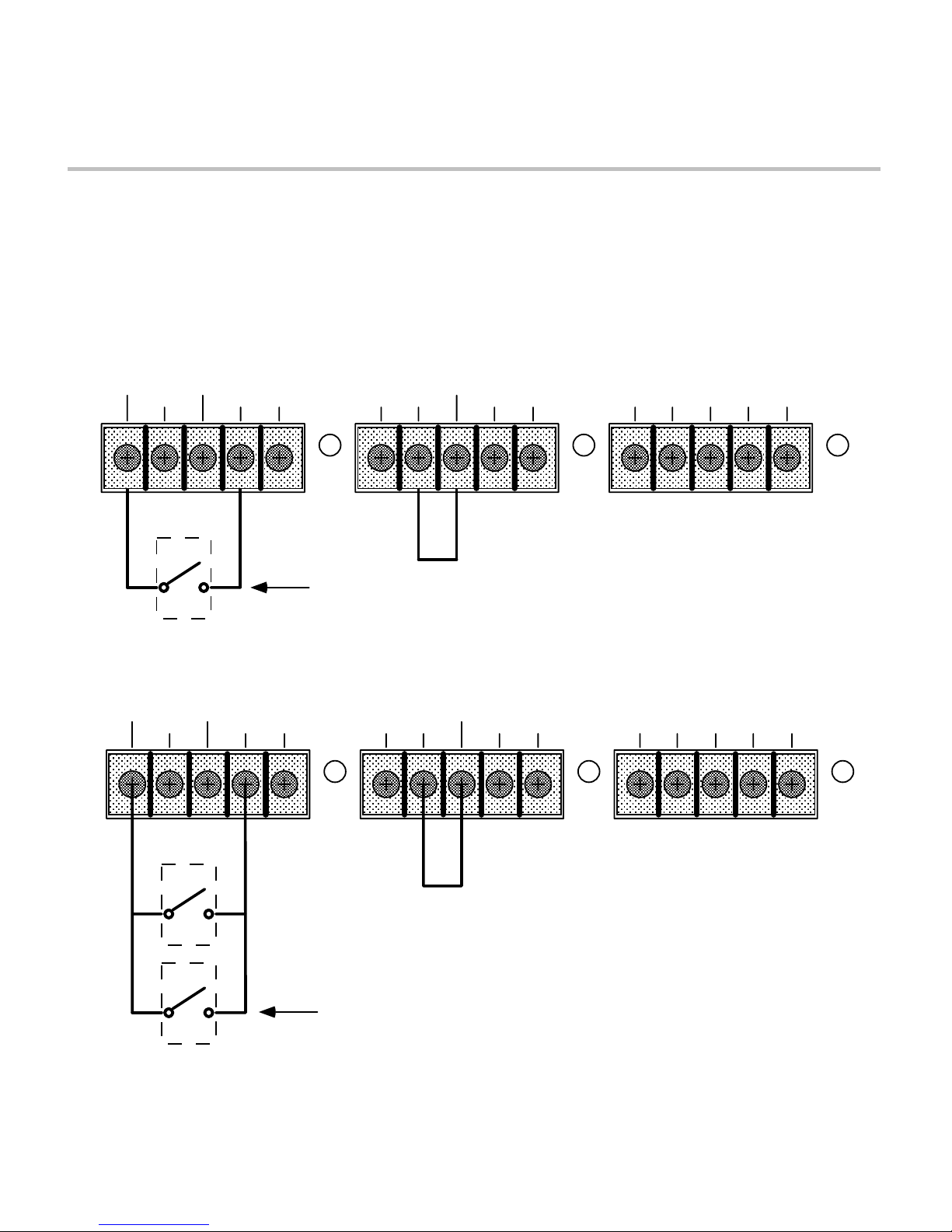
A normal, time-delayed on or off sequence may
be initiated in either of two ways: locally, via the
front panel key switch, or remotely, via a remotely
located maintained or momentary switch connect-
ed to the PowerLink’s rear panel terminal strip. In
addition, the behavior of any individual circuit may
be overridden by its corresponding front panel
ON/SEQ/OFF toggle switch.
The PowerLink’s control circuits turn on the circuits
in order from A to F when sequencing on, and
turn the circuits off in the reverse order from F to
A when sequencing off. The time for each step is
internally adjustable with a trim pot, with a range
of 0.2 to > 12 seconds per step. (Total time for the
entire sequence is from 1 second to > 1 minute).
Local control: Turning the key to the ON (or possi-
bly REM) position initiates an on sequence. Please
3

POWERLINK REMOTE AC POWER SEQUENCE CONTROLLER
note that in the absence of any signal applied to the
remote input, the REM position defaults to on. (If
the PowerLink has been changed from the factory-
preset Maintained Mode to Momentary Mode, you
must also press the START ON/OFF SEQUENCE
button. However, for purely local control, you should
leave the mode set to Maintained.)
When the unit is turned on with the key switch,
the PowerLink will stay on if all of its six circuits
are already on, or, if all circuits are off, will begin
turning on circuits starting with circuit A, then B,
etc. until all circuits are on. If the unit was in the
middle of sequencing off and had not yet turned
off all circuits, the lowest circuit that was currently
off will go on, so the sequence reverses without
ever deactivating the circuits that had not yet
gone off. The lowest off circuit turns on within 0.2
seconds, regardless of the setting of the delay
time trimpot. The next and all following circuits
turn on at intervals controlled by the trimpot. The
factory default setting is approximately 1 second
per step.
When the unit is turned on with the key switch,
the PowerLink will stay off if all circuits are
already off, or, if all circuits are on, will begin
turning off circuits starting with circuit F, then E,
etc. until all circuits are off. If the unit was in the
middle of sequencing on and had not yet turned
on all circuits, the highest circuit that is currently
on will go off, so the sequence reverses without
ever activating the circuits that had not yet turned
on. The highest on circuit turns off within 0.2 sec-
onds, regardless of the setting of the internal de-
lay time trimpot. The next and all following circuits
turn off at intervals controlled by the trimpot.
Remote Control: In the REM (center) position,
an on or off sequence is initiated by one or more
switches connected to the rear panel inputs, or,
in Momentary mode, also by the START ON/OFF
SEQUENCE button. The PowerLink responds
exactly as it does as described in the preceding
section on local control. See the next section for a
discussion of Remote Operating Modes.
When the key is in either the ON or OFF posi-
tion, the PowerLink’s sequencing circuits will not
respond to the rear panel remote control inputs. If
the key switch is later returned to the REM posi-
tion, the signals supplied to the rear panel remote
inputs will again control the unit.
Overriding a sequence: The PowerLink circuits
F
DE
C
B
A
PPOOWERLLINK 15
A
M
P
OFF
SEQ
ON
OFF
SEQ
ON
OFF
SEQ
ON
OFF
SEQ
ON
OFF
SEQ
ON
OFF
SEQ
ON
ON
OFF
REM
START
ON / OFF
SEQUENCE
REM
ON
UNSWITCHED OUTLET
REMOTE SEQUENCER
PowerLink front panel
120 VAC 60HZ
15A MAX RISK OF ELECTRIC SHOCK. DO NOT
OPEN. REFER SERVICING TO
QUALIFIED SERVICE PERSONNEL.
TO REDUCE THE RISK OF FIRE OR
ELECTRIC SHOCK DO NOT EXPOSE
THIS EQUIPMENT TO RAIN AND
MOISTURE.
CAUTION! 120 VAC
60 HZ
LOAD
15A
MAX
N'OUVREZ PAS–RISQUE
DE CHOC ELECTRIQUE
AVIS:
A
FORCE
OFF FEDCB
COM
GNDREM
COM
FORCE
ONREM
START
STATUS
+12V
MADE IN U.S.A.
ETL LISTED
C
ETL LISTED
CONFORMS TO
ANSI/UL STD. #1419
CERTIFIED TO
CAN/CSA C22.2 STD. NO. 1
9801539
PowerLink rear panel
4

POWERLINK REMOTE AC POWER SEQUENCE CONTROLLER
are turned on and off by six low level relays.
The relays are controlled by drivers that can be
activated either by the internal control circuits,
or directly by a three-position toggle switch.
The six ON/SEQ/OFF toggle switches (one per
circuit) can override the sequencing circuits, and
are intended as a secondary means of control
to allow individual on/off control of each circuit
for diagnostic purposes. Following are the three
positions of each ON/SEQ/OFF toggle switch.
Up: Circuit is on regardless of state of sequence
control circuits. Center: Circuit is controlled by the
sequence circuits (the normal position). Down:
Circuit is off regardless of state of sequence
control circuits. The center position is the normal
operating position, and allows control by the
sequencing circuits.
Signal relays: The PowerLink’s relays are ac-
cessible by the rear panel terminals labeled A
through F. These relays have an isolated common
(labeled RELAY COM) that is independent of the
chassis and signal grounds of the PowerLink, for
easy interfacing to virtually any other device that
could act as a slave to follow the PowerLink.
There is an internal jumper for each signal relay
that allows selection of the normally closed or
normally open contacts between each of the A to
F terminals and RELAY COM. The factory default
is that the contacts are open when the asso-ci-
ated circuit is off (normally open). The relay
contacts may be easily converted to normally
closed operation by moving six “suitcase” jump-
ers on the PowerLink’s circuit board. To do this,
rst disconnect the unit from AC power. Remove
the four screws that secure the top cover. There
are twelve small two-pin connectors labeled J1
through J12, located near the left side of the
largest circuit board. Six of the twelve are joined
by small black suitcase jumpers. To change the
mode, gently pull them up and reposition them in
accordance with Table 4 on page 7. Replace the
top cover and screws.
REMOTE OPERATING MODES
If the PowerLink will be controlled locally only, you
may skip this section and the next section
of the manual.
There are three remote operating modes avail-
able: Maintained Mode/Normally On, which is
the default, Maintained Mode/Normally Off, and
Momentary Mode.
The Momentary Mode on the PowerLink shares
the same characteristics as the Momentary Mode
on the Furman PowerPort, MiniPorts, ASD-120
Sequenced Power Distro, and PS-PRO and PS-
8R Power Sequencers. Remote inputs (REM,
FORCE ON, FORCE OFF) are controlled by ap-
plying at least 5 VDC or 6 VAC between the input
and the REM COM terminal.
This is the default control logic on all of our
existing and past power products. However, the
PowerLink’s inputs are enhanced in the following
ways: (1) They are polarity independent, and work
with positive, negative or AC control signals. (2)
They are optically isolated. The remote control
inputs have a oating common.
MAINTAINED MODE/NORMALLY ON (DE-
FAULT)
In the absence of any signal applied to the
remote input, the PowerLink will sequence on
as soon as power is applied, and the key switch
is turned to REM or ON. This is Maintained
Mode/Normally On. In this mode, voltage must be
continually applied to the REM input to keep the
PowerLink’s circuits off, when the key switch is in
the REM position. This mode is compatible with
all other Furman power products’ REM inputs.
Internal jumpers allow selection of either of two
other optional modes, as described below. Please
5

POWERLINK REMOTE AC POWER SEQUENCE CONTROLLER
also see Table 4, Internal User Settable Jumpers,
on page 7.
MAINTAINED MODE/NORMALLY OFF
This mode is just the reverse of the Maintained
Mode/Normally On mode. The PowerLink’s cir-
cuits stay off until voltage is applied to the REM
input. Voltage must be continually applied to keep
the unit on, when the key switch is in the REM
position. This setting will be useful to interface to
other brands of controller that have positive con-
trol logic (i.e. they put out a signal to indicate that
attached gear should turn on). In addition, since
the REM inputs are optically isolated, this mode
allows the PowerLink to sequence on if some
other source of AC line voltage is turned on.
MOMENTARY MODE
In Momentary Mode, the PowerLink has “memory”
— it only needs a momentary signal to change its
state from on to off, or off to on. When rst plugged
in (or after power is lost and re-applied for any
reason) the “memory” state is off. It will stay off until
sequenced on by the front panel START ON/OFF
SEQUENCE pushbutton or a momentary connec-
tion of the REM IN terminal to a voltage source
of at least ± 5 VDC or 6 VAC (130V max). The
sequence starts on the rising edge of the signal.
The rear panel +12V output may be used as a trig-
ger source. This is further explained in the section
“Setup for Remote Operation” below.
Once the PowerLink is on (or is sequencing on), ap-
plying voltage momentarily to the REM input starts
switching the PowerLink off, in descending se-
quence. Pushing the START ON/OFF SEQUENCE
button on the front panel is effectively the same as
applying a signal to the REM input (although the
actual connection is applied to an internal node, not
to the REM terminal on the rear barrier strip).
In Momentary Mode there are two additional
inputs that are not required, but may be useful
where multiple PowerLink’s are controlled from
remote locations. Please see the section
“Compatibility with Other Furman Products.”
SETUP FOR REMOTE
OPERATION
The barrier terminal strip on the PowerLink rear
panel allows a switch (or switches) to be con-
nected to turn the unit on or off at a distance, and
provides various power, status and relay closure
outputs. In the most basic conguration, only two
Class 2 wires and an SPST switch are needed to
initiate an on or off sequence. The switch may be
either a momentary or maintained-contact type.
An LED may also be installed at the remote end
to indicate that the power is on, but will require a
third wire.
MOMENTARY VS. MAINTAINED
CONTACT SWITCHING
An on-off switch of either kind may be used to
actuate the PowerLink’s remote operation. Main-
tained switches, such as most toggle switches
and push-on/push-off button switches, and includ-
ing the Furman RS-1 wall mount key lock switch,
are open until actuated, then stay closed until
actuated again. Momentary switches, including
the Furman RS-2 switch, are usually pushbutton
types that are normally open and stay closed only
as long as the button is pressed.
Maintained switches are generally most con-
venient when there is only one remote loca-
tion. When more than one location is required,
momentary switches offer the advantage that
either the turn-on or the turn-off sequence may be
started from any location.
The PowerLink is shipped factory-set for main-
tained operation. It may be easily converted to
momentary operation by moving a jumper plug
on the PowerLink’s circuit board. To do this, rst
6

POWERLINK REMOTE AC POWER SEQUENCE CONTROLLER
disconnect the unit from AC power. Remove the
four screws that secure the top cover. There are
three small two-pin connectors near the center of
the largest circuit board. A small black suitcase
jumper can be moved to set the mode. (Please
see Table 4 on this page for jumper numbers and
function description.)
MAINTAINED MODE/NORMALLY ON
A simple connection of the REM IN terminal to
the +12V terminal initiates an OFF sequence. Dis-
connecting it initiates an on sequence. If the cable
run is long, it is recommended that the REM IN
wire be tied to the PowerLink’s GND terminal
during on operation rather than leaving it oating.
This will require the use of a third conductor and
a double-throw switch. NOTE: The REM COM is
oating with respect to the ground of the +12V
source. To use the +12V with the REM input, the
REM COM terminal must be connected to the ad-
jacent ground terminal on the rear barrier block.
In Maintained Mode, do not use the START
ON/OFF SEQUENCE button on the front panel. If
you do press the button, the PowerLink, if on, will
start an off sequence that will last only until you
release the button.
MAINTAINED MODE/NORMALLY OFF
A simple connection of the REM IN terminal to
the +12V terminal initiates an on sequence. Dis-
connecting it initiates an off sequence. The other
instructions are identical to those in the Main-
tained Mode/Normally On section above. Again,
do not use the START ON/OFF SEQUENCE but-
ton on the front panel. If you do press the button,
the PowerLink, if off, will start an on sequence
that will last only until you release the button.
MOMENTARY MODE
A momentary connection of the REM IN terminal
to the +12V terminal will start the PowerLink’s
on/off sequence.
The +12V output on the rear barrier strip can be
used to trigger the REM input. As in Momentary
mode, the REM COM must be connected to the
adjacent GND terminal. This mode also requires
only two wires in the simplest case, +12V and
REM. You may wire any number of momentary
switches in parallel. In this mode the START
ON/OFF SEQUENCE button can also be used to
trigger an up/down sequence.
JMP1 Momentary Mode
JMP2 Maintained Mode, Normally ON (Factory
Default)
JMP3 Maintained Mode, Normally OFF
NOTE: Connect only ONE jumper of the
JMP1-JMP-3 group at a time
J1,2,5,6,9,10 Normally Open connection for low
level relays
A,D,B,E,C,F (factory default)
J3,4,7,8,11,12 Normally Closed connection for low level
relays A,D,B,E,C,F
STATUS OUTPUT
In all models, the STATUS terminal is an output
that may be used to illuminate an LED at the
remote location to indicate that power is available
at the PowerLink’s circuits. If it is high (+12V), the
unit is on (or at least in the process of sequencing
on); if low, the unit is off (or sequencing off). Sim-
ply connect the indicator LED between STATUS
and GND (a series resistor is not required). If
the LED does not light when the switch is in the
ON position, check the polarity and reverse the
LED leads if it is wrong. If a Furman RS-1 is the
controlling switch, contact Furman’s Tech Support
department for the proper wiring diagrams. The
STATUS output is a 12V source, current limited to
Table 4: Internal User Settable Jumpers
7

POWERLINK REMOTE AC POWER SEQUENCE CONTROLLER
10 mA. If you wish to use the STATUS output as
a voltage signal to some monitoring device, and
also wish to light a status LED on a remote panel,
put a 1 K Ohm 1/4-watt resistor in series with the
LED.
MULTIPLE UNITS
You can use more than one PowerLink to control
and sequence additional equipment. To control de-
vices remotely with one or more remote switches,
connect the REM and REM COM terminals of
all units together. You might need to connect the
+12V or GND terminals. Be sure that the mode
(momentary or maintained) of all units is set the
same. Connect a single maintained switch or one
or more momentary switches to the nearest
PowerLink, as discussed in the sections above.
Because the trigger sources provided on the
rear of the PowerLink (START and +12V) have a
GND that is isolated from the REM COM, it may
be necessary to connect GND to REM COM
on all units. This will usually be needed. The
GND and REM COM would be left isolated if the
PowerLink(s) are to be signalled by some other
source of voltage, such as the AC line, or a third
party controller. The +12V output or the START
output on a single PowerLink has enough output
current to switch dozens of REM inputs simulta-
neously, however, it is harmless to parallel the
+12V outputs.
If multiple PowerLink’s are controlled by one or
more momentary remote switches, they will all
change state (from on to off or vice versa) on each
rising edge of the voltage on the REM input ter-
minal. Pushing the START ON/OFF SEQUENCE
button will affect only the local PowerLink un-
less the START terminal on the rear barrier strip
of each unit is connected to the REM terminal
directly below it. To keep all units in sync, please
be sure to make this connection on all units. Once
the START and REM terminals are connected on
all units, any remote switch and any of the START
ON/OFF SEQUENCE button on any unit’s front
panel will toggle all the units. The key switch on
each unit’s front panel will turn off (or on) any indi-
vidual unit without affecting the other units.
The STATUS lines work the same in either mode.
Each reects the true state of the sequence
control circuit of its unit, and is affected by both
the “memorized” state and by the front panel key
switch. A separate LED must be used to indicate
the status of each PowerLink. NOTE: The STA-
TUS line will not reect changes caused by the
ON/SEQ/OFF mini-toggle override switches. The
STATUS output only indicates if the sequencing
control circuits are set to on or off.
To take care of the special (hopefully rare) case
of having several PowerLinks in parallel that
somehow get out of sync such that every time a
remote button is pushed, some units turn on and
others turn off, there is a special feature of the
REM signal line: Pushing the “START ON/OFF
SEQUENCE” button and holding it down for four
seconds, or holding the REM line high for at least
4 seconds will force all units to the off state, which
will put them back in sync. This may be the only
way to re-sync units other than disconnecting AC
power to all the units. Remember — operating the
front panel key switch does not affect the stored
state of the unit, even though it does temporarily
turn the outputs off. Please refer to the “Compat-
ibility ...” section of this manual below for another
way to keep PowerLink’s in sync.
8

POWERLINK REMOTE AC POWER SEQUENCE CONTROLLER
ADDITIONAL REMOTE FEATURES:
STATUS output signal on the rear panel allows
remote indication of whether the unit is on or off
(high indicates the unit is on or sequencing on,
low that the PowerLink is off or sequencing off)
+12V output terminal on rear has 40 mA
capacity to power many external devices
+12V supply and STATUS terminals are true
voltage sources, with current limiting circuits
that prevent damage if the output is heavily
loaded or shorted. This allows direct connection
of an LED to the STATUS output, or if a voltage
is desired from the STATUS output, an external
resistor in series with the LED (at least 1K)
will allow the STATUS output to rise to 12 VDC
while simultaneously lighting the LED.
A START output on the rear goes to +12V (with
a 1K source impedance) when the front panel
momentary START ON/OFF SEQUENCE push
button is pushed. This allows the PowerLink to
send a signal to other units that can be turned
on and off by a momentary voltage signal.
Note: This start function is merged with the
REM input on other Furman products.
COMPATIBILITY WITH OTHER
FURMAN PRODUCTS
The PowerLink’s remote control features are iden-
tical to those on the ASD-120 Sequenced Power
Distro, and similar to those on the PS-8R and
PRO Series with the following enhancements:
A separate LED (next to the front panel START
ON/OFF SEQUENCE button and labeled REM
ON) shows the “memorized” state. This LED will
be on whenever the remote control circuits are
set to turn the unit on, off if the remote control cir-
cuits are trying to turn the unit off. (Other Furman
products blink one of their status lights to indicate
the remote status.)
Because the remote control inputs are optically
isolated, they have a separate “ground” from
the chassis and control logic. In some cases this
“ground,” labeled REM COM, may need to be
connected to the signal ground GND. The Power-
Link has three remote input terminals. The REM
input is used in both Momentary and Maintained
modes, as described in the previous sections
on remote operating modes. FORCE ON and
FORCE OFF work only in momentary mode,
and are the same as the ON and OFF inputs of
the PowerPort. If the unit is off, applying power
momentarily to the FORCE ON input will set the
memorized state to on, which will start the on
sequence. Applying further control signals (of
any duration) to this input will have no effect. If
the unit is on (or sequencing on) applying power
momentarily to the FORCE OFF input will set
the memorized state to off, which will start the off
sequence. Applying further control signals (of any
duration) to this input has no effect.
The FORCE ON and FORCE OFF inputs provide
an assured method of controlling multiple Pow-
erLinks, with no possibility that the units will get
out of sync with each other, as can happen when
using the regular REM toggle input. These two
inputs also make the PowerLink directly compat-
ible with the PowerPort.
As is the case with the PowerPort, the disadvan-
tage of using the separate ON and OFF inputs
instead of the single REM toggle input is that two
momentary switches (and at least three wires)
are required at every remote control location.
Where a single PowerLink is controlled from
multiple remote locations there is no advantage
to using the separate ON and OFF inputs, unless
the switch location makes it difcult for you to tell
whether the system is currently on or off.
9

POWERLINK REMOTE AC POWER SEQUENCE CONTROLLER
LIMITED WARRANTY
The Furman PowerLink is warranted against
failures due to defective parts or faulty workman-
ship for a period of three years after delivery to
the original owner. During this period, Furman
will make any necessary repairs without charge
for parts or labor. Shipping charges to the factory
or repair station must be prepaid by the owner;
return shipping charges (via UPS Ground) will be
paid by Furman.
This warranty applies only to the original owner
and is not transferable. Also, it does not apply to
repairs done other than by the Furman factory or
Authorized Repair Stations.
This warranty shall be cancelable by Furman at
its sole discretion if the PowerLink unit has been
subjected to physical abuse or has been modied in
any way without written authorization from Furman.
Furman’s liability under this warranty is limited to
repair or replacement of the defective unit.
Furman will not be responsible for incidental or
consequential damages resulting from the use or
misuse of its products. Some states do not allow
the exclusion of incidental or consequential dam-
ages, so the above limitations may not apply to
you. This warranty gives you specic legal rights,
and you may also have other rights which vary
from state to state. Warranty claims should be
accompanied by a copy of the original purchase
invoice showing the purchase date (if a Warranty
Registration Card was mailed in at the time of
purchase, this is not necessary). Before returning
any equipment for repair, please read the impor-
tant information on service below.
SERVICE
Before returning any equipment for repair, please
be sure that it is adequately packed and cush-
ioned against damage in shipment, and that it
is insured. We suggest that you save the origi-
nal packaging and use it to ship the product for
servicing. Also, please enclose a note giving your
name, address, phone number and a description
of the problem.
NOTE: All equipment being returned for repair
must have a Return Authorization (RA) Number.
To get an RA Number, please call the Furman
Service Department, (707) 763-1010, Ext. 120 or
121, between 8 am and 5 pm U.S. Pacic Time.
Please display your RA Number prominently on
the front of all packages.
10

Furman Sound, Inc.
1997 South McDowell Blvd.
Petaluma, California 94954-6919 USA
Phone: 707-763-1010
Fax: 707-763-1310
Web: www.furmansound.com
E-mail: [email protected]
Made in China
SPECIFICATIONS
VOLTAGE AND CURRENT
Input Voltage: 120 VAC, 50/60 Hz.
Power Consumption: 8.4 watts
POWER SEQUENCING
Delay Interval: 0.2 to 10 seconds per step
(adjustable with internal trimpot)
REM CONTROL INPUTS
Optically isolated, AC or DC drive, 12K ohm input
impedance. Operates at 5 VDC or 6-130 VAC.
Max 130 VAC from REM COM to chassis
SIGNAL RELAY OUTPUTS
Common isolated from chassis and control ground.
130 VAC max from relay common to chassis.
Relay can switch 1/2 amp max @ 125 VAC,
or 1/2 amp max @ 24 VDC.
Internally congurable to normally closed
or normally open
AC OUTLETS
Two unswitched convenience circuits
on the rear, and one on the front
MECHANICAL:
Weight: 5.5 lbs (2.5 kg)
Dimensions: 1.75” H x 19” W x 7.125 ” D
(4.4 x 48.3 x 18 cm)
Construction: Steel chassis, zinc chromate plating;
.125” brushed and black anodized aluminum
front panel.
Safety Information: All current-carrying components
are UL/CSA listed.
This manual suits for next models
1
Table of contents
Other Furman Recording Equipment manuals

Furman
Furman CN-1800S User manual

Furman
Furman RR-131 User manual

Furman
Furman PS-PRO User manual

Furman
Furman PS-PRO User manual

Furman
Furman PS-8R II User manual

Furman
Furman PS-PRO E II User manual

Furman
Furman CN-3600SE User manual

Furman
Furman MP-15 User manual

Furman
Furman PS8 R II User manual

Furman
Furman MP-30 User manual