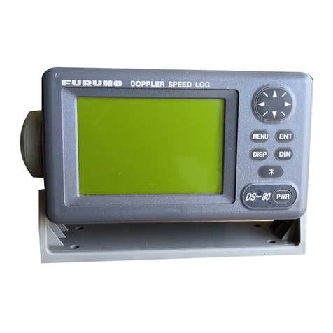
Furuno GS-100 User manual

SATELLITE SPEED LOG
GS-100
OPERATOR'S MANUAL
www.furuno.com
Model

The paper used in this manual
is elemental chlorine free.
・FURUNO Authorized Distributor/Dealer
9 52 Ashihara cho,
Nishinomiya, 662 8580, JAPAN
A
:
MAY
2014
Printed in Japan
All rights reserved.
B
:
MAY
28, 2014
Pub. No.
OME-72790-B
(
YOTA
)
GS-100
0 0 0 1 7 8 6 2 4 1 1

i
IMPORTANT NOTICE
General
• This manual has been authored with simplified grammar, to meet the needs of international us-
ers.
• The operator of this equipment must read and follow the descriptions in this manual. Wrong op-
eration or maintenance can cancel the warranty or cause injury.
• Do not copy any part of this manual without written permission from FURUNO.
• If this manual is lost or worn, contact your dealer about replacement.
• The contents of this manual and equipment specifications can change without notice.
• The example screens (or illustrations) shown in this manual can be different from the screens
you see on your display. The screens you see depend on your system configuration and equip-
ment settings.
• Save this manual for future reference.
• Any modification of the equipment (including software) by persons not authorized by FURUNO
will cancel the warranty.
• All brand and product names are trademarks, registered trademarks or service marks of their
respective holders.
How to discard this product
Discard this product according to local regulations for the disposal of industrial waste. For disposal
in the USA, see the homepage of the Electronics Industries Alliance (http://www.eiae.org/) for the
correct method of disposal.
How to discard a used battery
Some FURUNO products have a battery(ies). To see if your product has a battery(ies), see the
chapter on Maintenance. Follow the instructions below if a battery(ies) is used. Tape the + and -
terminals of battery before disposal to prevent fire, heat generation caused by short circuit.
In the European Union
The crossed-out trash can symbol indicates that all types of batteries
must not be discarded in standard trash, or at a trash site. Take the
used batteries to a battery collection site according to your national
legislation and the Batteries Directive 2006/66/EU.
In the USA
The Mobius loop symbol (three chasing arrows) indicates that Ni-Cd
and lead-acid rechargeable batteries must be recycled. Take the
used batteries to a battery collection site according to local laws.
In the other countries
There are no international standards for the battery recycle symbol. The number of symbols can
increase when the other countries make their own recycle symbols in the future.
Cd
Ni-Cd Pb

ii
SAFETY INSTRUCTIONS
Indicates a condition that can cause death or serious
injury if not avoided.
Indicates a condition that can cause minor or moderate
injury if not avoided.
WARNING
CAUTION
WARNING CAUTION
Do not disassemble or modify
the equipment.
Fire, electrical shock or serious
injury can occur.
Turn off the power immediately if
water leaks into the equipment or
smoke or fire is coming from the
equipment.
Failure to turn off the equipment can
cause fire or electrical shock.
Contact a FURUNO agent for service.
The glass of an LCD panel breaks
easily. Handle the LCD carefully.
Injury can result if the glass breaks.
Use the correct fuse.
A wrong fuse can cause fire or serious
damage to the equipment.
Do not connect/disconnect the
signal cable while turning the
power on.
The unit may be damaged.
About the TFT LCD
The TFT LCD is constructed using the latest LCD techniques, and displays 99.99% of its pixels. The
remaining 0.01% of the pixels may drop out or blink, however this is not an indication of malfunction.
Warning, Caution Prohibitive Action Mandatory Action
Safety Instructions for the Operator
No single navigation aid (including
this unit) should ever be relied
upon as the exclusive means for
navigating your vessel.
The navigator is responsible for
checking all aids available to confirm
his position. Electronic aids are
intended to assist, not replace, the
navigator.

SAFETY INSTRUCTIONS
iii
WARNING CAUTION
Turn off the power at the
switchboard before beginning the
installation.
Fire or electrical shock can result if the
power is left on.
Safety Instructions for the Installer
Be sure that the power supply is
compatible with the voltage rating
of the equipment.
Connection of an incorrect power
supply can cause fire or damage the
equipment.
Ground the equipment to prevent
electrical shock and mutual
interference.
Observe the following compass safe
distances to prevent interference to a
magnetic compass:
Standard
compass
Steering
compass
Antenna
Unit
Display
Unit
Junction
Box
Type
GS-1001
GS-1002
GS-1003
0.70 m 0.45 m
0.60 m 0.40 m
0.75 m 0.50 m
Display
Unit
(option)
DS-600 0.60 m 0.40 m
Have a qualified serviceman do the
installation.
Only qualified personnel should work
inside the equipment.
Use the specified power cable.
Fire can result if an incorrect cable is
used.
The mounting location for the units
must satisfy the following
conditions:
- Away from rain and water splash
- Out of direct sunlight
- Away from air conditioner vents
- Moderate and stable in temperature
and humidity

iv
TABLE OF CONTENTS
FOREWORD ..................................................................................................................vii
SYSTEM CONFIGURATIONS......................................................................................viii
1. OPERATIONAL OVERVIEW .................................................................................1-1
1.1 Controls...................................................................................................................... 1-1
1.2 How to Turn the Power On/Off................................................................................... 1-2
1.3 How to Adjust the Brilliance of the Display and Panel ............................................... 1-3
1.4 Main Menu Overview ................................................................................................. 1-3
1.5 List Overview.............................................................................................................. 1-4
2. DISPLAYS..............................................................................................................2-1
2.1 Display Modes............................................................................................................ 2-1
2.2 How to Select the Background Color ......................................................................... 2-2
2.3 Navigation Display ..................................................................................................... 2-2
2.4 Integrity Display.......................................................................................................... 2-5
3. SETTINGS..............................................................................................................3-1
3.1 Display Menu ............................................................................................................. 3-1
3.1.1 How to set the time for smoothing.................................................................. 3-1
3.1.2 How to set the current direction and wind angle ............................................ 3-1
3.2 Trip Menu ................................................................................................................... 3-2
3.2.1 How to calculate the trip distance .................................................................. 3-2
3.2.2 How to set the total distance .......................................................................... 3-2
3.3 System Menu ............................................................................................................. 3-3
3.3.1 How to change the user password................................................................. 3-3
3.3.2 SNTP setting .................................................................................................. 3-4
3.4 How to Set the Demo Mode ....................................................................................... 3-4
3.5 GNSS Menu ............................................................................................................... 3-6
3.5.1 How to select the positioning system ............................................................. 3-6
3.5.2 How to set the positioning condition............................................................... 3-6
3.6 Beacon/SBAS Menu .................................................................................................. 3-7
3.6.1 How to select the offset information to use .................................................... 3-7
3.6.2 How to set SBAS............................................................................................ 3-7
3.6.3 How to disable a satellite ............................................................................... 3-7
3.7 Other Setting Menus for Antenna Unit ....................................................................... 3-8
3.7.1 How to reset the sensor ................................................................................. 3-8
3.7.2 How to clear the sensor settings .................................................................... 3-8
3.7.3 How to set the time for dead reckoning.......................................................... 3-8
3.7.4 How to restart heading data output after restoration of heading data............ 3-9
3.8 Device List..................................................................................................................3-9
3.8.1 How to open the device list from the menu.................................................... 3-9
3.8.2 Device menu ................................................................................................ 3-10
3.9 I/O Menu .................................................................................................................. 3-11
3.9.1 How to set the output data 1, 2, 3 or 4 ......................................................... 3-11
3.9.2 How to set the sentences to output to the Ethernet ..................................... 3-12
3.9.3 How to select the input data......................................................................... 3-13
3.9.4 Line monitor log............................................................................................ 3-14
3.9.5 How to set the digit number for sentences................................................... 3-16
3.10 How to Clear the Memory ........................................................................................ 3-16
4. NOTICES................................................................................................................4-1
4.1 Audio Notice Type...................................................................................................... 4-1

TABLE OF CONTENTS
v
4.2 Ship Speed Notice......................................................................................................4-1
4.3 Trip Notice ..................................................................................................................4-2
5. ALERTS .................................................................................................................5-1
5.1 Overview.....................................................................................................................5-1
5.2 Alert List......................................................................................................................5-3
5.3 Alert Log .....................................................................................................................5-3
5.4 How to Acknowledge Alerts........................................................................................5-4
6. BERTHING DISPLAY ............................................................................................6-1
6.1 Berthing Display Overview .........................................................................................6-1
6.2 Controls for the Display Unit DS-600..........................................................................6-2
6.3 Various Settings .........................................................................................................6-3
6.4 Display Range ............................................................................................................6-6
6.4.1 How to select a range.....................................................................................6-6
6.4.2 How to pre-set ranges ....................................................................................6-7
6.5 Track...........................................................................................................................6-7
6.5.1 Types of tracks ...............................................................................................6-7
6.5.2 How to select the type of track to display .......................................................6-8
6.5.3 How to select the past track format ................................................................6-9
6.5.4 How to select the predicted track plot interval................................................6-9
6.6 How to Show, Hide Navigation Data and 3-axis Speed Data.....................................6-9
6.7 Berthing Line ............................................................................................................6-11
6.7.1 How to register a berthing line......................................................................6-11
6.7.2 How to edit a berthing line............................................................................6-12
6.7.3 How to delete a point or a line......................................................................6-12
6.7.4 How to send the berthing lines data to DS-600............................................6-13
6.7.5 How to confirm the berthing lines .................................................................6-13
7. MAINTENANCE, TROUBLESHOOTING ..............................................................7-1
7.1 Maintenance ...............................................................................................................7-1
7.2 Fuse Replacement .....................................................................................................7-1
7.3 Consumable Parts ......................................................................................................7-2
7.4 Troubleshooting..........................................................................................................7-3
7.5 Equipment Information ...............................................................................................7-4
7.6 Self Test .....................................................................................................................7-5
7.7 Backup........................................................................................................................7-7
7.8 Replacement Parts Settings .......................................................................................7-8
7.8.1 How to reset the operating time for replacement parts ..................................7-8
7.8.2 Correction for the replaced rate gyro..............................................................7-9
8. INSTALLATION .....................................................................................................8-1
8.1 Equipment List............................................................................................................8-1
8.2 Mounting.....................................................................................................................8-2
8.2.1 Display unit GS-1002 .....................................................................................8-2
8.2.2 Antenna unit GS-1001....................................................................................8-4
8.2.3 Junction box GS-1003....................................................................................8-8
8.3 Wiring .........................................................................................................................8-9
8.3.1 Junction box .................................................................................................8-10
8.3.2 Display unit...................................................................................................8-12
8.3.3 Antenna unit .................................................................................................8-13
8.4 Adjustments..............................................................................................................8-14
8.4.1 Language .....................................................................................................8-14
8.4.2 Device mode ................................................................................................8-14
8.4.3 Unit ...............................................................................................................8-14
8.4.4 Datum ...........................................................................................................8-15

TABLE OF CONTENTS
vi
8.4.5 Time format .................................................................................................. 8-15
8.4.6 Equipment ID ............................................................................................... 8-16
8.4.7 Correction menu........................................................................................... 8-16
8.4.8 Alert mode.................................................................................................... 8-18
8.4.9 IP address.................................................................................................... 8-19
8.5 Connections and Adjustments with Optional Interface Unit IF-2503........................ 8-19
8.6 Installation, Adjustment of Optional Display Unit DS-600 ........................................ 8-20
8.6.1 Installation of the display unit DS-600.......................................................... 8-20
8.6.2 Menu settings for DS-600 ............................................................................ 8-22
8.6.3 Adjustments for GS-1002............................................................................. 8-25
8.7 Speed Test............................................................................................................... 8-25
APPENDIX 1 MENU TREE .......................................................................................AP-1
APPENDIX 2 LIST OF TERMS/SYMBOLS ..............................................................AP-5
APPENDIX 3 TIME DIFFERENCES..........................................................................AP-9
APPENDIX 4 GEODETIC CHART LIST .................................................................AP-10
APPENDIX 5 WHAT IS SBAS? ..............................................................................AP-11
APPENDIX 6 DIGITAL INTERFACE (IEC 61162-1/2/450) .....................................AP-12
APPENDIX 7 PARTS LIST/LOCATION..................................................................AP-21
APPENDIX 8 JIS CABLE GUIDE ...........................................................................AP-24
SPECIFICATIONS .....................................................................................................SP-1
PACKING LISTS.......................................................................................................... A-1
OUTLINE DRAWINGS................................................................................................. D-1
INTERCONNECTION DIAGRAMS .............................................................................. S-1
INDEX..........................................................................................................................IN-1

vii
FOREWORD
A Word to the Owner of the GS-100
Congratulations on your choice of the FURUNO GS-100 Satellite Speed Log. We are confident
you will see why the FURUNO name has become synonymous with quality and reliability.
Since 1948, FURUNO Electric Company has enjoyed an enviable reputation for innovative and
dependable marine electronics equipment. This dedication to excellence is furthered by our ex-
tensive global network of agents and dealers.
Your equipment is designed and constructed to meet the rigorous demands of the marine envi-
ronment. However, no machine can perform its intended function unless properly installed and
maintained. Please carefully read and follow the operation and maintenance procedures set forth
in this manual.
We would appreciate feedback from you, the end-user, about where we are achieving our purpos-
es.
Thank you for considering and purchasing FURUNO equipment.
Features
The main features of the GS-100 are as shown below.
• High-resolution color LCD
• Comprehensive navigation data displays
• Highly accurate speed data
• External USB memory capability (for maintenance)
• Vessel speed for port and starboard at any position of the hull by built-in satellite compass
• Optional DS-600 (display unit) can be connected to the GS-100 to add berthing support capa-
bility
• Notices: Ship speed, Trip
• Alerts: Warning, Caution
• Ethernet port for connection to a LAN
Program No.
**: Minor change
Unit Name No.
GS-1001 GPS 48502630**
ANT 2051522-02.**
GS-1002 MAIN 2051552-01.**
DS-600 Starter 6652000-01.**
Booter 6652001-02.**
Main 6652002-02.**

viii
SYSTEM CONFIGURATIONS
Basic configuration is shown with solid line.
Antenna Unit
GS-1001
Display Unit GS-1002
Network Equipment,
HUB, etc.
Nav Equipment,
IF-2503, etc.
Rectifier
PR-62
Environmental category
Antenna unit: Exposed to the weather
All other units: Protected from the weather
Junction Box
GS-1003
24 VDC
Rectifier
PR-240
110/220 VAC
1ø, 50/60 Hz
100-115/220-230 VAC
1ø, 50/60 Hz
USB Flash Memory
MENU
ESC ENT
LIST
DISPLAY
123
456
789
ACK
0
BRILL
DS-600 (Sub Display)

1-1
1. OPERATIONAL OVERVIEW
1.1 Controls
The keys are arranged according to the function.
No. Key Function
Menu screen Display mode
1 MENU ESC • Closes the menu.
• Quits current operation.
Opens the menu.
2 ENT Confirms a selection. Switches the screen between main
(digital navigation data) and sub
(graphic screen).
3 Cursorpad • Sor T: Select the menu item.
• W: Returns one layer in multi-layer
menu.
• X: Go to one layer in multi-layer
menu.
Sor T: Switches display on the in-
tegrity display.
4 LIST • Opens the list.
• Switches the list (any display →active alert →alert log →device list →any
display). Long-press to switch the list in reverse order.
5 DISPLAY Opens the display mode. Switches the screen between THD
and SDME modes.
6 0 to 9 • Selects and confirms the menu item.
• Enters a numeric character.
–
7 ACK Acknowledges an unacknowledged alert when the pop-up appears.
8 BRILL Opens the brilliance adjustment window.
Adjusts the display brilliance when the adjustment window opens.
9(Power) • Turns the power on when the key is protruded, then the key is recessed.
• Turns the power off when the key is recessed, then the key is protruded.
10 USB port For connection of USB flash memory.
MENU
ESC ENT
LIST
DISPLAY
123
456
789
ACK
0
BRILL
Operation keys
Function keys
1
1
3
3
4
4
2
2
5
5
6
6
7
7
8
8
9
9
MENU
ESC ENT
LIST
DISPLAY
123
456
789
ACK
0
BRILL
10
10

1. OPERATIONAL OVERVIEW
1-2
Key sound
When you operate a key, a single beep sounds. If you do not need the key beep, de-
activate the beep sound as follows (see section 1.4):
1. Press the MENU ESC key to open the main menu.
2. Select [2 Speed/Trip Setting] then [4 Sound].
3. Select [2 Key Sound].
4. Select [2 Off].
5. Press the MENU ESC key to close the main menu.
1.2 How to Turn the Power On/Off
Press the key to turn the power on. The start-up screen appears for 30 seconds
then the screen set at the [6 Device Mode] menu (see paragraph 8.4.2) appears.
Note: The screen refreshes slower in low ambient temperature.
To turn the power off, press the key.
Self test
results
Start-up screen
SDME mode THD mode

1. OPERATIONAL OVERVIEW
1-3
1.3 How to Adjust the Brilliance of the Display and
Panel
1. Press the BRILL key to show the following setting window.
2. To adjust the display brilliance, press the cursorpad (Wor X) or the BRILL key
(setting range: 0 to 15, default: 14 for day mode/6 for night mode).
3. To adjust the panel brilliance, press the cursorpad (Sor T) (setting range: 0 to
9, default: 7 for day and night modes).
4. Press the MENU ESC key to close the setting window.
Note 1: The default settings for night mode is 6 for [Display] and 7 for [Panel]. If the
display is difficult to see when switching to the night mode, press the cursorpad (X) to
increase the display brilliance.
Note 2: When you switch the brilliance mode, the last-used brilliance for the selected
mode is set.
Note 3: When the brilliance is preset, the background color is also preset (see
section 2.2). So both the brilliance and the background color are restored to the de-
fault when long-pressing the ENT key.
1.4 Main Menu Overview
1. Press the MENU ESC key to open the main menu.
Switch the color mode between
day mode and night mode.
Long-press to restore the
settings to default of day mode.
Triangles indicate
additional menus.

1. OPERATIONAL OVERVIEW
1-4
2. Press the cursorpad (Sor T) to select a menu item then press the ENT key. You
can also select a menu item by pressing the numeric keys. This manual states this
operating procedure as “Select [No. menu name].” The menu items that have a X
indicate additional menus.
3. Select an option.
4. Press the MENU ESC key to close the main menu.
1.5 List Overview
The LIST key displays the active alert list, alert log list and device list, in the sequence
shown below.
Second layer Third layer
Any display Active Alert
Alert Log
Device List
: Short-press the LIST key
: Long-press the LIST key

2-1
2. DISPLAYS
2.1 Display Modes
The GS-100 has two main display modes. The SDME (Speed and Distance Measur-
ing Equipment) mode measures speed and distance. The THD (Transmitting Heading
Device) outputs heading data to external equipment. You can switch between the two
display modes with the DISPLAY key. The mode is indicated at the top left corner as
follows:
*: See paragraph 8.4.2.
Each mode has a main (digital navigation data) and sub (graphic) display, and you can
switch between them with the ENT key. For a description of the sub displays, see sec-
tions 2.3 and 2.4.
The example below shows sample screens when the SDME mode is the “Device
Mode”. The screens for the THD mode are similar.
The trip distance can be reset from the main screen of the SDME mode. Long-press
(more than one second) the 0key to reset the trip distance.
Indication Description
Mode selected on the [Device Mode]* menu.
Top: Currently selected mode.
Bottom: Mode selected on the [Device Mode]* menu.
Press the
ENT key.
Main (digital navigation data) Sub (graphic screen: Navigation)
Press the
ENT key.
Sub (graphic screen: Integrity)
Press the
DISPLAY key.
Main (digital navigation data)

2. DISPLAYS
2-2
2.2 How to Select the Background Color
You can select the background color to suit lighting conditions or environment (see
section 1.3).
1. Press the MENU ESC key to open the main menu.
2. Select [1 Display] then [1 Background Color].
3. Select [1 White] or [2 Black].
4. Press the MENU ESC key to close the main menu.
2.3 Navigation Display
The navigation display in the SDME mode shows various navigation data.
How to select the data to display
You can select the data to display on the windows 1 to 5.
1. Press the MENU ESC key to open the main menu.
2. Select [1 Display] then [2 Navigation Display].
Window1
Window2
Window3
Window4
Window5

2. DISPLAYS
2-3
3. Select [1 Window1].
4. Select [1 Roll/Pitch] or [2 SDME].
5. Select the options for windows 2 to 5 as well.
Note: The options [SDME], [Current True], [Wind] and [Depth] require the external
input.
6. Press the MENU ESC key to close the main menu.
[Roll/Pitch], [Position], [Time & Date], [Heave] or [Trip Time] selected
Displays external input data
for doppler SOG/COG.
Window1 Window2
Window3 Window4 Window5
Heading
Status
indication
Roll
Ship’s position
Time and date
Heave
Rate of turn
GNSS speed
over ground
and course
over ground
Trip time
Trip distance
Total distance
Calculation state
(Normal, DR (Dead-Rechoning),
Stopped (HDG stopped),
SYS FAULT (System fault))
HDOP: 2D
PDOP: 3D
Satellite
number
common
to ANT1
and ANT2
Spinner
rotates when
the equipment
is functioning
normally.
: Starboard
: Port
(
(
Pitch
: Starboard
: Port
(
(
: Up
: Down
(
(
See page
AP-8.

2. DISPLAYS
2-4
[SDME], [Current True], [Wind], [Depth] or [Drift] selected
Note: When there is no external input or the input value is invalid, the applicable win-
dow is blank. When the input value is valid, ":EXT" is displayed.
Status indications
Note: No. 3 to 12 are reserved for future use.
No. Indication System
2D positioning 3D positioning
1GP-2D GP-3D GPS
2 GP-S2D GP-S3D GPS + SBAS
3 GP-D2D GP-D3D GPS + Differential
4 GA-2D GA-3D GALILEO
5 GA-S2D GA-S3D GALILEO + SBAS
6 GA-D2D GA-D3D GALILEO + Differential
7 GL-2D GL-3D GLONASS
8 GL-S2D GL-S3D GLONASS + SBAS
9 GL-D2D GL-D3D GALILEO + Differential
10 GN-2D GN-3D Multi
11 GN-S2D GN-S3D Multi + SBAS
12 GN-D2D GN-D3D Multi + Differential
13 No Fix No fixed
Heading
Status
indication
External
doppler speed
over ground
and course
over ground
External
current speed
and direction
External wind
speed and
direction*
External depth
GNSS speed
over ground
and course
over ground
Drift
Trip distance
Total distance
Spinner
rotates when
the equipment
is functioning
normally.
HDOP: 2D
PDOP: 3D
* [WIND T]: True, [WIND TH]: Theoretical, [WIND R]: Relative (See paragraph 3.1.2.)
: Starboard
: Port
(
(
Rate of turn
: Starboard
: Port
(
(
Calculation state
(Normal, DR (Dead-Rechoning),
Stopped (HDG stopped),
SYS FAULT (System fault))
See page
AP-8.
Satellite
number
common
to ANT1
and ANT2

2. DISPLAYS
2-5
3-axis speed display
The circle at the center of the display shows the own ship’s speed.
2.4 Integrity Display
The integrity display, available in the THD mode, provides information about GPS sat-
ellite position and signal quality. There are three integrity displays: GNSS, graph for
satellite angle and graph for signal noise ratio.
Use the cursorpad (Sor T) to change the displays, in the following sequence.
*: These triangles are displayed in the following conditions:
• Current direction: Selected [Current True] in the [Window2] menu.
• Wind velocity: Selected [Wind] in the [Window3] menu.
• Drift angle: Selected [Drift] in the [Window5] menu.
**: When the current indication method is [Flow from] (set on the [Current] menu, see
paragraph 3.1.2), the blue icon for current direction turns 180° and is displayed outside
of the circle.
***: The speed value at the position where the antenna is installed is more accurate.
N, E, S, W:
Bearing scale Stern
Bow
Picture
of ship
Bow velocity
Wind velocity* (Magenta)
N
Broadside speed
at stern position***
Speed for
heading
Drift angle*
(Brown)
Current direction*/** (Blue)
Broadside speed at
bow position***
Heading velocity
Stern velocity
GNSS
Graph: signal
noise ratio
Graph:
satellite angle
: Press the ▲ key.
: Press the ▼ key.

2. DISPLAYS
2-6
GNSS
The GNSS display shows the condition of satellite positioning system. Number, azi-
muth and elevation angle of all satellites (if applicable) in view of your receiver appear.
*: Satellites are displayed in order of acquisition, not numerical order.
Elevation 60° Elevation 30° Elevation 0°
Receiver signal level
Bars show signal level.
Satellite numbers*
Left: for
ANT1
Right: for
ANT2
Green: Satellites acquired by ANT1
Purple: Satellites acquired by ANT2
Blue: Satellites common to ANT1 and ANT2
Gray: Blocked satellites
Satellites used for positioning (Satellite numbers used for positioning
are displayed in white, or black if not used for positioning.)
Other manuals for GS-100
1
Table of contents
Other Furuno Boating Equipment manuals