Furuno FCV-38 User manual

www.furuno.com
A
ll brand and product names are trademarks, registered trademarks or service marks of their respective holders.
Installation Manual
Stabilized FISH SIZE INDICATOR
Model FCV-38
(Product Name: FISH FINDER)
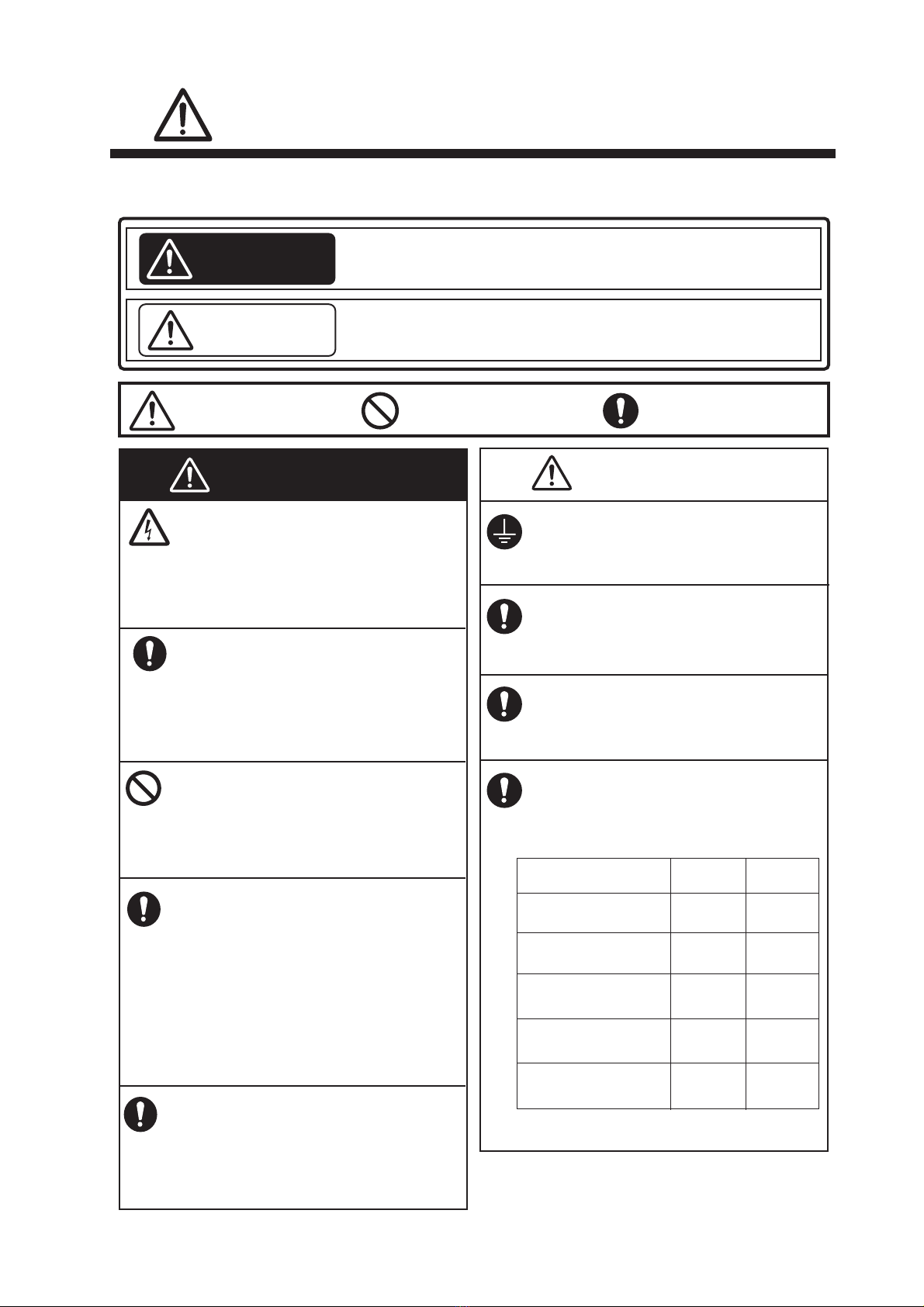
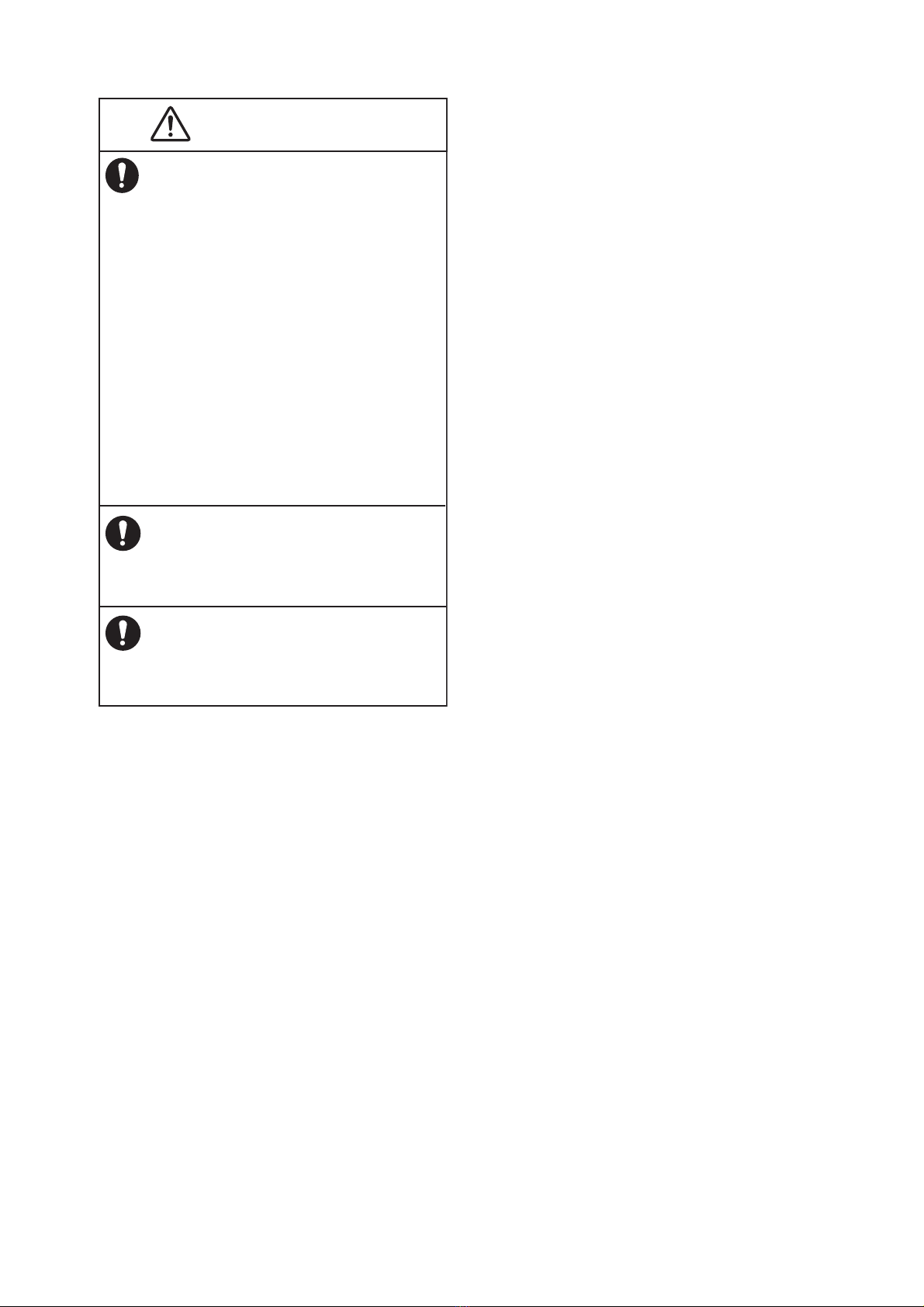
SAFETY INSTRUCTIONS ................................................................................................ i
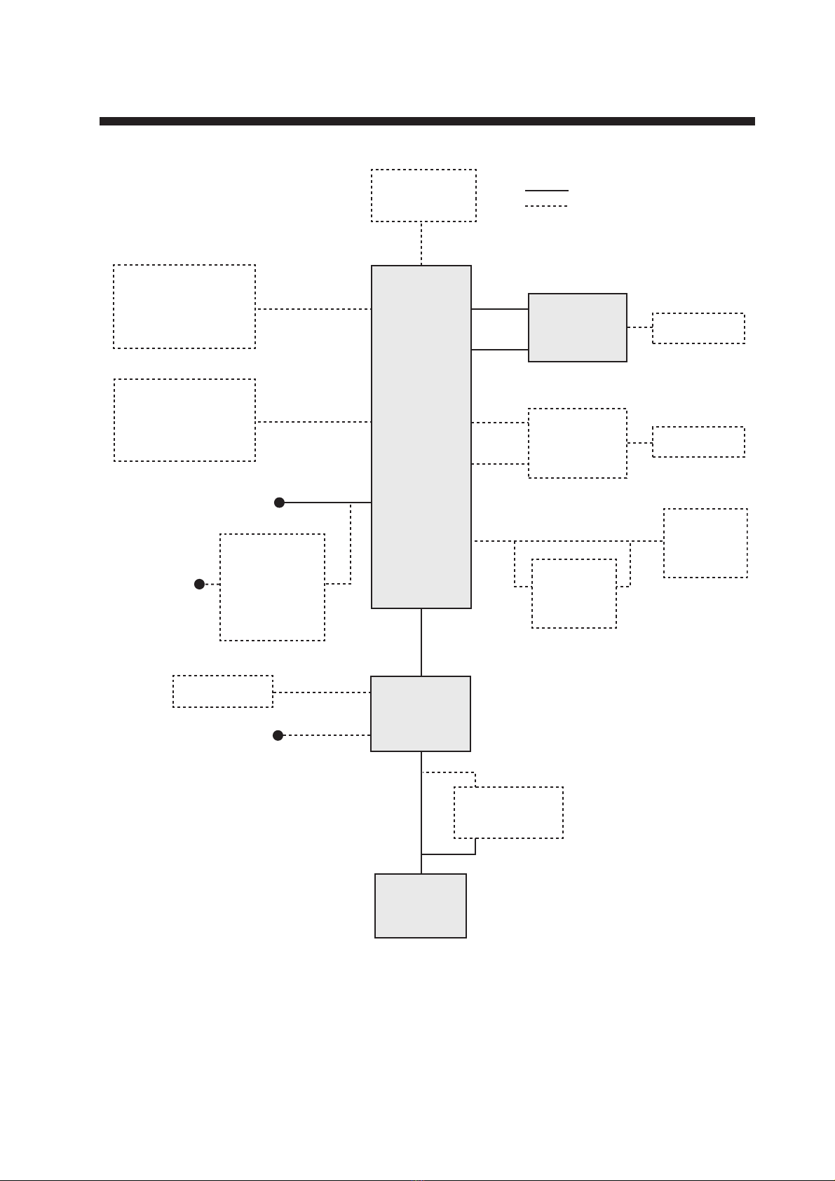
SYSTEM CONFIGURATIONS........................................................................................ iii
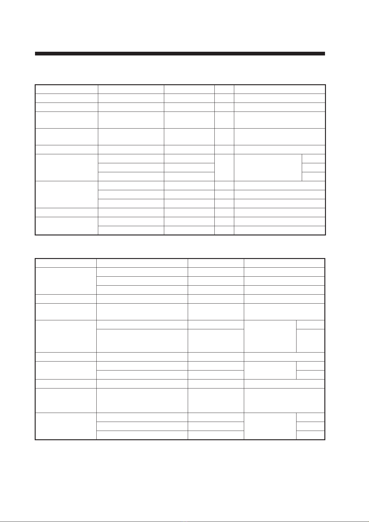
EQUIPMENT LISTS........................................................................................................ iv
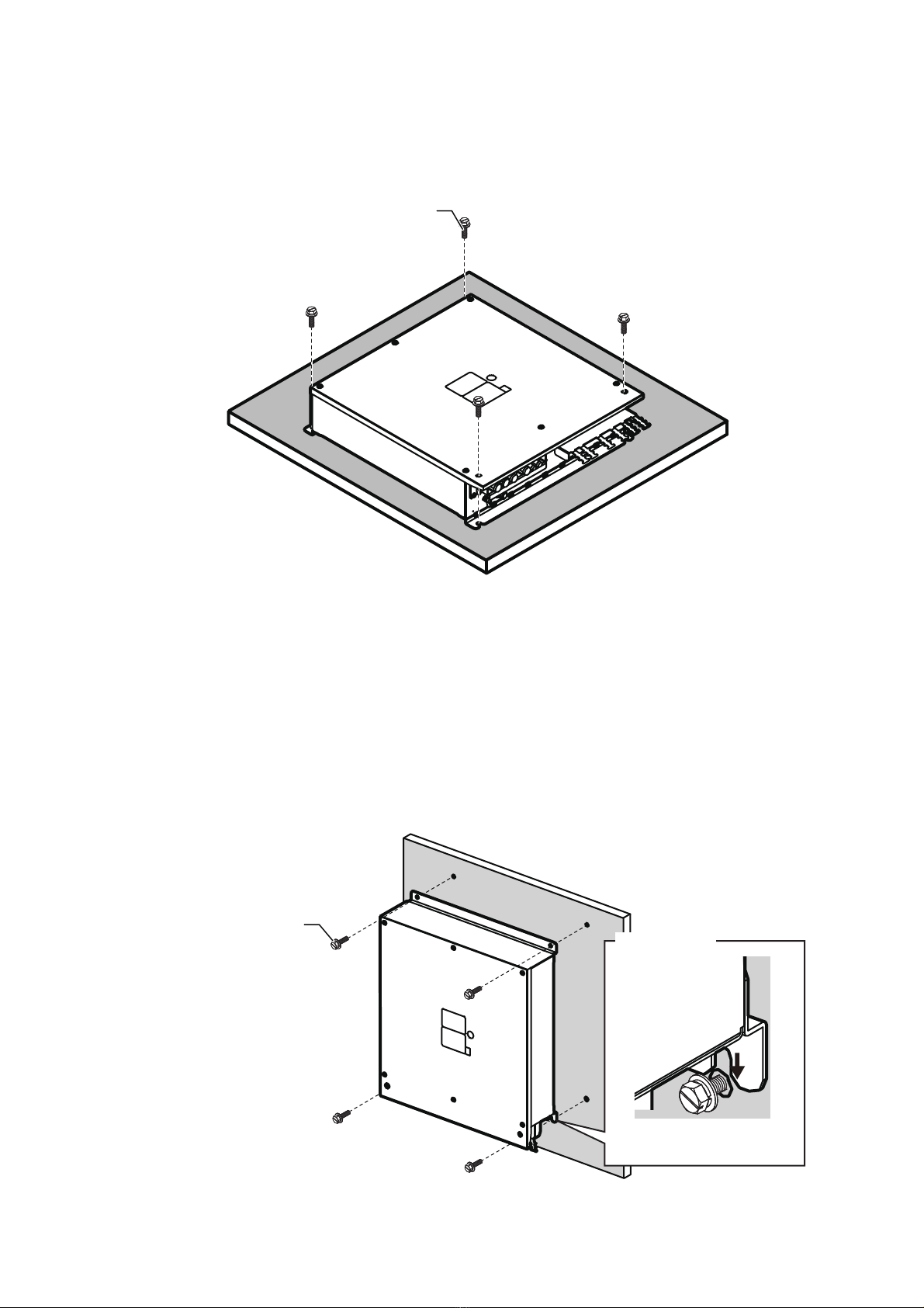
1. MOUNTING..............................................................................................................1-1
1.1 Processor Unit ...................................................................................................................1-1
1.2 Transceiver Unit.................................................................................................................1-3
1.3 Trackball Control Unit ........................................................................................................1-4
1.4 Transducer.........................................................................................................................1-7
1.5 Junction Box (Option) ......................................................................................................1-10
1.6 DVI/USB Repeater (Option).............................................................................................1-10
2. WIRING....................................................................................................................2-1
2.1 Processor unit ....................................................................................................................2-2
2.2 Transceiver Unit.................................................................................................................2-6
2.3 Trackball Control Unit ........................................................................................................2-8
2.4 Transducer.......................................................................................................................2-10
2.5 Junction Box (option) .......................................................................................................2-11
2.6 DVI/USB Repeater (Option).............................................................................................2-13
2.7 Input/Output Sentences (NMEA0183) .............................................................................2-14
3. INITIAL SETTINGS..................................................................................................3-1
3.1 How to Set the Language and Measurement Unit .............................................................3-1
3.2 How to Set the [Service] Menu ..........................................................................................3-2
3.3 Communication Port Setting ..............................................................................................3-7
3.4 External Echo Sounder Setting........................................................................................3-10
3.5 Calibration Setting............................................................................................................3-12
3.6 Stabilization Setting .........................................................................................................3-16
3.7 How to Take a Still Image of the RX Monitor...................................................................3-19
3.8 Reset to Default Setting...................................................................................................3-19
3.9 Retrofit from FCV-30........................................................................................................3-20
APPENDIX 1 JIS CABLE GUIDE .............................................................................AP-1
PACKING LISTS ......................................................................................................... A-1
OUTLINE DRAWINGS ................................................................................................ D-1
INTERCONNECTION DIAGRAMS.............................................................................. S-1

7KHSDSHUXVHGLQWKLVPDQXDO
LVHOHPHQWDOFKORULQHIUHH
࣭)85812$XWKRUL]HG'LVWULEXWRU'HDOHU
$VKLKDUDFKR
1LVKLQRPL\D-$3$1
$ 6(3
3ULQWHGLQ-DSDQ
$OOULJKWVUHVHUYHG
3XE1R ,0($
$.08 )&9

i
SAFETY INSTRUCTIONS
The installer must read the applicable safety instructions before attempting to operate or install the
equipment.
Indicates a potentially hazardous situation which, if not avoided,
could result in death or serious injury.
WARNING
Indicates a potentially hazardous situation which, if not avoided,
can result in minor or moderate injury.
CAUTION
Warning, Caution Prohibitive Action Mandatory Action
WARNING
ELECTRICAL SHOCK HAZARD
Do not open the equipment unless
totally familiar with electrical circuits
and service manual.
Only qualified personnel are allowed to
work inside the equipment.
Turn off the power at the mains
switchboard before beginning the
installation.
Fire, electrical shock or serious injury can
result if the power is left on or is applied
while the equipment is being installed.
Install the transducer according to the
installation instructions.
Failure to install the transducer correctly
may result in water leakage and damage
to the ship's hull.
For wooden or FRP vessel using a
steel tank, attach a zinc plate to the
hull to prevent electrolytic corrosion.
Electrolytic corrosion can, in the worst
case, result in loss of the transducer.
Be sure no water leaks in at the
transducer mounting location.
Water leakage can sink the vessel. Also,
confirm that the transducer will not be
loosened by ship vibrations. The installer
of the equipment is solely responsible
for the proper installation of the
equipment. FURUNO will assume no
responsibility for any damage associated
with improper installation.
CAUTION
Observe the following safe compass
distances to prevent interference to a
magnetic compass:
Do not transmit with the transducer
out of water.
The transducer may become damaged.
Use the proper cable and fuse.
Use of an incorrect cable and fuse can
damage the equipment and cause fire.
Standard
compass
Steering
compass
2.15 m 1.35 m
Processor Unit
(CV-380)
2.15 m 1.35 m
Transceiver Unit
(CV-382)
0.30 m 0.30 m
Trackball Control Unit
(RCU-026)
1.10 m 0.70 m
Junction Box
(CV-304)
0.35 m 0.30 m
DVI/USB Repeater
(TM000-FDX06)
Ground the equipment to prevent
electrical shock and mutual
interference.

SAFETY INSTRUCTIONS
ii
CAUTION
Do not allow warm water or any other
liquid other than seawater or
freshwater to contact the transducer.
Damage to the transducer may result.
The transducer cable must handled
carefully, following the guidelines
below.
- Keep the cable away from oil and fuels.
- Keep the cable away from locations
where it may be damaged during the
installation.
- Do not carry the transducer using only
the cable. The cable may become
damaged or disconnected.
- Do not shorten the transducer cable.
- Do not paint the cable.
The cable sheath is made of chloroprene
or vinyl chloride, which are easily dam-
aged by plastic solvents such as toluene.
Locate the cables away from plastic
solvents.
Do not install the transducer where
noise or air bubbles is present.
Performance will be affected.

iii
SYSTEM CONFIGURATIONS
RS-485
USB䠆2
RS-485
USB䠆2
USB port
USB3.0: 2 ports
USB2.0: 2 ports
100/110/115/
220/230 VAC
1ø, 50/60Hz
Display Unit*3
USB device䠆2
USB device䠆2
*1䠖A maximum of four USB devices including RCU-026 can be connected to the processor unit.
*2: To use the USB port on the RCU-026, connect the RCU-026 to the USB port on the processor
unit, using the USB cable supplied with the RCU-026. If you do not use the USB port on the
RCU-026, the USB connection between the RCU-026 and processor unit is not required.
*3: To extend the distance between the processor unit and the monitor unit/USB device, use the
optional DVI/USB repeater.
*4: The transceiver unit CV-302 for FCV-30 is available.
Rectifier Unit
RU-1746B-2
or
AC/DC Power
Supply Unit
PR-241
:
Standard supply
:
Optional or local supply
External KP
Trackball
Control Unit
RCU-026
Trackball
Control Unit
RCU-026
12-24 VDC
NMEA 0183 port,
5 ports
NETWORK2 port
NETWORK1
port
USB device*1, *3
(USB mouse,
USB flash memory,
USB keyboard, etc.)
HDMI port 2 ports
Processor
Unit
CV-380
100-120/220-240 VAC
1ø, 50/60 Hz
Nav equipment,
Satellite compassTM,
Radio communication,
Net sonde, etc.
Junction Box
CV-304
Transceiver
Unit䠆4
CV-382
Transducer
CV-303
Ethernet
HUB
HUB-101
Network
Sounder
DFF3

iv
EQUIPMENT LISTS
Standard supply
Optional supply
Name Type Code No. Qty Remarks
Processor Unit CV-380 - 1
Transceiver Unit CV-382 - 1
Trackball Control
Unit
RCU-026 - 1
Transducer CV-303 *ROHS* - 1 15 m cable (φ22 mm),
w/data sheet sticker (silver)
Thru-Hull Pipe TFB-1600 - 1
Installation
Materials
CP24-02900(10M) 001-208-050
1
LAN cable between
processor unit and
transceiver unit
10 m
CP24-02910(20M) 001-208-060 20 m
CP24-02920(30M) 001-208-070 30 m
Installation
Materials
CP10-09700 000-036-275 1 For processor unit
CP02-09801 001-581-570 1 For transceiver unit
CP24-02300 000-027-673 1 For RCU-026
Accessories FP24-00801 001-418-410 1 For RCU-026
Spare Parts SP02-06001 001-569-280 1 For processor unit
SP03-17661 001-249-760 1 For transceiver unit
Name Type Code No. Remarks
Junction Box CV-304-10 - 10 m cable
CV-304-20 - 20 m cable
CV-304-50 - 50 m cable
Rectifier Unit RU-1746B-2 000-030-439
AC/DC
Power Supply Unit
PR-241 000-037-820
Cable Assembly HDMI-TO-DVI-L=10.3M 001-407-170 HDMI cable be-
tween proces-
sor unit and
display unit
10.3 m
HDMI-TO-DVI-L=5.3M 001-407-180 5.3 m
Ethernet Hub HUB-101 000-011-762
Cable Assembly 6TPSH-XH12X2-L5.0SP2 001-186-310-10 For RCU-026 5 m
6TPSH-XH12X2-L10SP2 001-186-320-10 10 m
Flush Mount OP24-27 001-171-820 For RCU-026
Transducer Fixing
Kit
T-625-A 001-096-720 For noise reduction
caused by ship move-
ment.
Cable Assembly PARTS_WO2511 001-578-140 LAN cable for
DVI/USB
repeater
30 m
PARTS_WO2512 001-578-150 50 m
PARTS_WO2513 001-578-160 100 m

EQUIPMENT LISTS
v
Installation
Materials
CP10-10100 000-036-244 LAN cable be-
tween proces-
sor unit and
transceiver unit
(Waterproof
type)
10 m
CP10-10110 000-036-245 15 m
CP10-10120 000-036-246 30 m
CP10-10130 000-036-247 40 m
CP10-10140 000-036-248 50 m
CP10-10150 000-036-722 100 m
DVI/USB Repeater TM000-FDX06_TXRX_30M 001-578-110 TX/RX units
w/LAN cable
30 m
TM000-FDX06_TXRX_50M 001-578-170 50 m
TM000-FDX06_TXRX_100M 001-578-180 100 m
TM000-FDX06_TXRX 001-578-190 TX/RX units
TM000-FDX06_RX 001-578-120 RX unit
TM000-FDX06_TX 001-578-130 TX unit
Cable Assembly MJ-A3SPF0024-035C 000-157-943-10
RNS-08-132 001-107-540-10 5 m cable between DVI/
USB repeater (TX) and
the processor unit
Name Type Code No. Remarks

EQUIPMENT LISTS
vi
This page is intentionally left blank.

1-1
1. MOUNTING
1.1 Processor Unit
The processor unit can be installed on a deck or bulkhead.
Mounting consideration
Select a mounting location, keeping in mind the following points:
• Locate the unit out of direct sunlight and away from heat sources.
• Locate the unit away from places subject to water splash and rain.
• Select a mounting location considering the length of the cables to be connected to
the unit.
• Select a location where shock and vibration are minimal.
• Be sure the mounting location is strong enough to support the weight of the unit.
• Referring to the outline drawings at the back of this manual, allow sufficient space
for maintenance and service.
• A magnetic compass will be affected if the unit is placed too close to the magnetic
compass. Observe the compass safe distances at the front of this manual to prevent
interference to a magnetic compass.
• For bulkhead installations, secure the unit so that the cable entrance faces down-
ward.
NOTICE
Do not apply paint, anti-corrosive sealant or contact spray to
coating or plastic parts of the equipment.
Those items contain organic solvents that can damage
coating and plastic parts, especially plastic connectors.

1. MOUNTING
1-2
1.1.1 Deck mount
1. Drill four pilot holes in the mounting location for mounting bolts (M6 bolts or coach
screws φ6), referring to the outline drawing at the back of this manual.
2. Secure the unit using the four hex head slot bolts (M6×20, supplied).
1.1.2 Bulkhead mount
1. Drill four pilot holes in the mounting location for mounting bolts (M6×20, supplied),
referring to the outline drawing at the back of this manual.
2. Screw two hex head slot bolts into the lower pilot holes. Leave 5 mm of thread vis-
ible.
3. Set the notches of the unit onto the screws fastened at step 2.
4. Screw two hex head slot bolts into the upper fixing holes.
5. Fasten all screws tightly to secure the unit in place.
Hex head slot bolt
(M6×20, 4 pcs䠅
Detailed view
Set the notches of the unit
to the bolts.
Hex head slot bolt
(M6×20, 4 pcs䠅

1. MOUNTING
1-3
1.2 Transceiver Unit
The transceiver unit can be installed on a deck.
Mounting Consideration
Select a mounting location, keeping in mind the following points:
• The transceiver unit generates heat so the mounting location should be well venti-
lated and dry.
• Referring to the outline drawings at the back of this manual, allow sufficient space
for maintenance and service.
• A magnetic compass will be affected if the unit is placed too close to the magnetic
compass. Observe the compass safe distances at the front of this manual to prevent
interference to a magnetic compass.
• If the front panel of the unit is oriented to port, its motion sensor faces the bow, i.e.,
the arrow mark of the NOTE label on the transceiver unit orients to bow. After instal-
lation, compensate for installation angle error, referring to chapter 3.
Deck Mount
1. If necessary, install a channel base on the mounting location, consulting with the
shipyard.
Note: Take account of the direction of the transceiver unit. Position the transceiv-
er unit so that the left side faces the bow as viewed from the cover side.
2. Drill four pilot holes in the mounting location for mounting screws (M12, supplied
locally), referring to the outline drawing at the back of this manual.
3. Fasten the transceiver unit to the channel base with M12 bolts.
If necessary, reinforce the transceiver unit against vibration by stays extending
from the eyebolts.
4-
f
14
35
410±1
270±0.5
(15)
370
10
#300
#300 446
(40) (340)
(410±1)
(50)
(170)
(4-M12-6H)
(270±0.5)
(30)
Eye bolt
(4 pcs.)
Cable clamp
Terminal board
Ground terminal
Channel base
Deck side
cable entry
(Fixing holes of
Transceiver unit)
Top view (Transceiver unit) Top view (Channel base)
Fixing holes
Bow
direction

1. MOUNTING
1-4
1.3 Trackball Control Unit
The trackball control unit can be installed on a desktop or flush mounting (option). For
desktop mounting, the unit can be tilted or laid flat.
Mounting Consideration
Select a mounting location, keeping in mind the following points:
• Select a location where the control unit can be operated easily.
• Locate the unit out of direct sunlight and away from heat sources.
• Locate the unit away from places subject to water splash and rain.
• Referring to the outline drawings at the back of this manual, allow sufficient space
for maintenance and service.
• Select a mounting location considering the length of the cables to be connected to
the unit.
• A magnetic compass will be affected if the unit is placed too close to the magnetic
compass. Observe the compass safe distances at the front of this manual to prevent
interference to a magnetic compass.
• Select a location where shock and vibration are minimal.
1.3.1 Desktop mount
How to mount the unit tilted
Use the desk fixing plate to mount the unit tilted.
1. Attach the desktop fixing plate to the trackball control unit, using the two washer
head screws (M3×8, supplied).
Desktop fixing plate
Washer head screw
(M3×8, 2 pcs.)

1. MOUNTING
1-5
2. Secure the unit using the two self-tapping screws (φ5×20, supplied).
How to install the unit flat on the desktop
Secure the trackball control unit without the desktop fixing plate to install the unit flat
on the desktop.
1. Drill four mounting holes of 4 mm diameter referring to the outline drawings at the
back of this manual.
2. Secure the unit with the four washer head screws (M3×12, supplied) from the un-
derside of the desktop.
Self-tapping screw
(ø5×20, 2 pcs.)
Washer head screw
(M3×12, 4 pcs.)

1. MOUNTING
1-6
1.3.2 Flush mount
Note: For flush mounting in a panel, the mounting surface must be flat. Do not install
the unit on an uneven surface.
Prepare the optional flush mount kit (OP24-27) for flush mounting the trackball control
unit.
1. Make a mounting hole in the mounting location, referring to the outline drawing at
the back of this manual.
2. Set the unit to the mounting hole.
3. Attach the four FM fixing plates to the unit from the rear side, using the washer
head screws (M3×8).
4. Fasten each wing bolt until the protector for the screw is firm against the mounting
panel.
5. Fasten each wing nut tightly to secure the unit.
FM fixing plate
(4 pcs.)
Washer head screw
(M3×8, 4 pcs.)
Protector
Wing bolt
Wing nut
FM fixing plate assy.

1. MOUNTING
1-7
1.4 Transducer
The performance of the fish finder depends on the transducer position.
Refer to the drawing for transducer tank installation at the end of this manual. The
transducer tank T-625 (code: 000-037-649) should be prepared locally.
Mounting consideration
Note 1: Carefully handle the transducer. Do not lift the transducer by holding the ca-
ble, nor drop it.
Note 2: The gasket sizes in the thru-hull pipe are different for two types of CV-303.
When replacing the transducer, make sure that the gasket in the thru-hull pipe is ap-
plied with the cable.
If the gasket is required, arrange the appropriate gasket according to the cable diam-
eter.
• A place least affected by air bubbles should be selected since turbulence blocks the
sounding path.
• Select a place least influenced by engine noise.
• Select a place without other sounder interference. The transducer should be sepa-
rated from other transducers with the same frequency by 2.5 m or farther.
• Install the transducer face parallel to the sea surface.
• Orient the transducer bow mark to ship’s bow
within ±5 degree.
It is known that air bubbles are fewest at the
place where the bow first falls and the next
wave raises, at usual cruising speed. In small,
slow-speed boats, the position between 1/3 and
1/2 of the ship’s length from the bow is usually
a good place.
Refer to the installation drawing for the trans-
ducer, combined with the thru-hull pipe TFB-
1600.
Note: The face of the transducer must be facing the sea bottom in normal cruising
trim of the boat.
Cable
diameter
Color of data
sheet sticker*
Gasket of TFB-1600 Remarks
Name Type
22.0 mm Silver Gland gasket B 02-153-4204
19.4 mm White Gland gasket 02-153-4203 Cable for FCV-30
NOTICE
Do not install the transducer on the inner side of the hull.
The signal strength is reduced and may affect the accuracy of measurements.
Do not cover the transducer with FRP resin.
The heat generated when the resin hardens may damage the transducer.
For mounting the transducer, use a flange for transducer tank.
ø5
BOW
Transducer face
Bow mark

1. MOUNTING
1-8
Data sheet sticker
The transducer is supplied with three data sheet stickers in silver on the transducer
cable as follows. Refer to section 3.2.6.
Note: If the data sheet stickers in white (Not in silver) are attached on the cable for
FCV-30, conductive tape should be wound around the exposed shield. See
section 2.4 for details.
1.4.1 About transducer casing
The FURUNO transducer tank is finished with lacquer primer to prevent corrosion in
storage. After welding the casing to ship's hull, remove the lacquer primer, using lac-
quer thinner. Coat casing with same paint as used on the ship's hull.
Methods to remove lacquer primer from the tank
1. Dissolve and remove paint with solvent.
2. Remove rust, coating, oil film, etc, with a blaster.
3. Remove with a disk sander or foil brush.
1.4.2 Transducer fixing plate kit (option) assembly
You can use the optional T-625-A transducer fixing plate kit to reduce noise caused
by ship movement for transducer tank T-625 (local supply).
1. Remove the press plate from the transducer fixing plate and fit the fixing plate to
the transducer.
[CV-303 15M] sticker
(Attached on the base of
the transducer) [TRANSDUCER DATA] sticker (2pcs.)
(Attached near the connectors )
Be careful of bow direction.
Press plate
Transducer
Transducer fixing plate

1. MOUNTING
1-9
2. Wrap the two flank sponges around the sides of the transducer. Face the cut side
toward the transducer and insert the uncut part between the transducer and the
TD attachment.
3. Secure the sponge in place with a hose clamp (stainless band). Apply silicone
sealant (local supply) to the screws to prevent seizing and corrosion.
4. Refit the press plate as before. Tighten the double nuts at 63.5Nm torque.
5. To attach to the ship’s bottom, refer to the T625 tank drawing.
TD attachment
Insert the uncut
part between the
transducer and the
TD attachment.
Flank sponge
Stainless band
Silicone sealent

1. MOUNTING
1-10
1.5 Junction Box (Option)
If the length of cable between the transducer and transceiver unit is more than 15 m,
the optional junction box CV-304 (with 10 m, 20 m or 50 m cable) can be used for cable
extension.
Keep in mind the following points when
selecting a location.
• Leave sufficient space at the sides and
rear of the unit to facilitate mainte-
nance.
• A magnetic compass will be affected if
the junction box is placed too close to
the magnetic compass. Observe the
compass safe distances in "SAFETY
INSTRUCTIONS" on page i to prevent
interference to a magnetic compass.
• Connect a copper strap (local supply)
to the ground terminal.
Use four bolts (M5, local supply) to secure the junction box.
For bulkhead mounting, fasten two bolts for the lower notches, leaving 5 mm of thread
exposed from the bolt head. Set the notches of the junction box on the two bolts, the
fasten two bolts for the upper bolt holes. Secure the junction box in place with all four
bolts fastened tightly.
Note: For bulkhead installations, the cable entry must face downwards.
1.6 DVI/USB Repeater (Option)
To extend the distance between the display unit and the processor unit/USB device,
use the optional DVI/USB repeater. Cable extension without the repeater can result in
signal loss and incorrect data display.
The DVI/USB repeater has two units, one transmitter unit and one receiver unit. The
following figure shows the general connection for the DVI/USB repeater.
Notches
Ground terminal
Bolt holes
USB
Device
(Max.
2 units)
Monitor
Unit
DVI/USB
Repeater
Receiver
Unit
DVI/USB
Repeater
Transmitter
Unit
Processor
Unit
HDMI
USB
(Type A)
USB
(Type B)
DVILANLANDVIDVI
USB
(Type A)

1. MOUNTING
1-11
The DVI/USB repeater can be installed on a deck or bulkhead. Cable connection is
slightly different between transmitter and receiver unit. For this reason, it is important
that you identify each unit before mounting. The following table and figure show how
to identify the units.
Mounting consideration
• Locate the unit away from heat sources.
• Locate the unit away from places subject to water splash and rain.
• Select a mounting location considering the length of the cables to be connected to
the unit.
• Select a location where shock and vibration are minimal.
• Referring to the outline drawings at the back of this manual, allow sufficient space
for maintenance and service.
• A magnetic compass will be affected if the unit is placed too close to the magnetic
compass. Observe the compass safe distances at the front of this manual to prevent
interference to a magnetic compass.
• For bulkhead installations, secure the unit so that the cable entrance faces down-
ward.
• The maximum cable length for the video signal cable is as follows:
• HDMI-TO-DVI-L cable between processor unit and transmitter unit: 5.3 m
• DVI-D/D S-LINK cable between receiver unit to monitor unit: 5 m
Unit What to look for
Receiver Unit Female SRCN connector, USB type A connector ×2
Transmitter Unit Male SRCN connector, USB type B connector
Receiver Unit
LAN
DVI-D
Ground
terminal
Power
Transmitter Unit
SRCN2A
Male connector
SRCN2A
Female connector
USB
(Type B)
LAN
DVI-D
Ground
terminal
Power
USB
(Type A)

1. MOUNTING
1-12
Mounting procedure
1. Drill four pilot holes in the mounting location for mounting screws (φ5×20, local
supply), referring to the outline drawing at the back of this manual.
2. Screw the four self-tapping screws into the pilot holes. Leave 5 mm of thread vis-
ible.
3. Hang the unit onto the screws fastened at step 2.
4. Fasten all screws tightly to secure the unit in place.
Self-tapping
screw
(ø5×20, 4 pcs)
Detailed view
Hang on the unit onto the
self-tapping screws.
Other manuals for FCV-38
1
Table of contents
Other Furuno Boating Equipment manuals