FUTABA CGY750 User manual

TABLE OF CONTENTS
•Introduction-----------------------------------------------------------------2
•
WarrantyandRepairService(inU.S.A.)
---------------------------------2
•Features----------------------------------------------------------------------2
•Contents----------------------------------------------------------------------2
•Precautions------------------------------------------------------------------3
•Specifications---------------------------------------------------------------3
•ReplacementandOptionalItems--------------------------------------4
•GyroSensorInstallation------------------------------------------------------ 4
•
ConnectingtheCGY750
----------------------------------------------------5
•TXSet-up------------------------------------------------------------------------- 6
•GovernorInstallation-----------------------------------------------------6
•GovernorFuselageSettingPrecautions-----------------------------6
•FirstMap------------------------------------------------------------------------- 7
•OpeningScreen-------------------------------------------------------------7
•HomeScreen----------------------------------------------------------------7
•WarningDisplay------------------------------------------------------------8
•SettingMenus--------------------------------------------------------------8
•S.BUSBasicSetting--------------------------------------------------------9
•SwashBasicSetting-----------------------------------------------------10
•SwashDetailSetting----------------------------------------------------12
•TXAileron/ElevatorGyroGainSet-up------------------------------13
•FlightTuningSetting---------------------------------------------------14
•RudderBasicSetting----------------------------------------------------15
•GovernorBasicSetting-------------------------------------------------16
•GovernorSpeedSetting------------------------------------------------ 18
•GovernorOperation-----------------------------------------------------18
•RecommendedGyroGainSettings----------------------------------18
•AdjustmentsDuringtheTestFlight---------------------------------18
•TipsforUsingtheCGY750GovernorwithElectricModels---- 18
•FlightTuneExpertSetting---------------------------------------------19
•RudderGyroExpertSetting-------------------------------------------19
•GovernorExpertSetting----------------------------------------------- 20
•ConditionMenu---------------------------------------------------------- 21
•CGY750V2-3D-MAP------------------------------------------------------22
•CGY750V2-F3C-MAP-----------------------------------------------------24
•F3CStyleTuningSection-----------------------------------------------26
Gyro
: Instructionsforgyrofunctions
Governor
: Instructionsforgovernorfunctions
Technicalupdatesandadditionalprogrammingexamplescanbefoundat:
www.futaba-rc.com/faq
1M23N24915
V2.0
~

2
INTRODUCTION
WARRANTY & REPAIR SERVICE (IN U.S.A.)
,IDQ\ GLI¿FXOWLHVDUH HQFRXQWHUHGZKLOHVHWWLQJ XSRU RSHUDWLQJ\RXU
&*< SOHDVH FRQVXOW WKH LQVWUXFWLRQ PDQXDO ¿UVW )RU IXUWKHUDV-
VLVWDQFH\RXPD\DOVRUHIHUWR\RXUKREE\GHDOHURUFRQWDFWWKH)XWDED
6HUYLFH&HQWHUDWWKHZHEVLWHID[RUWHOHSKRQHQXPEHUOLVWHGEHORZ
www.futaba-rc.com or www.hobbyservices.com
Fax (217)-398-7721,Tel (217) 398-0007
,I\RXDUHXQDEOHWRUHVROYHWKHLVVXHSDFNWKH V\VWHPLQLWVRULJLQDO
FRQWDLQHUZLWKDQRWHHQFORVHGDQGDWKRURXJKDFFXUDWHGHVFULSWLRQRI
WKHGLI¿FXOW\,QFOXGHWKHIROORZLQJLQ\RXUQRWH
• Symptoms (including when the problem occurred)
• System (Transmitter, Receiver, Servos and model numbers)
• Model (Model name)
• Model numbers and quantity
• Your Name, Address and Telephone number
6HQGWKHUHVSHFWLYHLWHPVWRWKHDXWKRUL]HG)XWDED6HUYLFH&HQWHU$G-
GUHVVEHORZ
Futaba Service Center
3002 N Apollo Drive Suite 1
Champaign, IL 61822
7KH)XWDED® &*< LV D FRPELQHG D[LV KHDG-
LQJKROG$9&6J\URDQGKHDGVSHHGJRYHUQRULQ
RQHER[,WVFXWWLQJHGJH0(060LFUR(OHFWUR
0HFKDQLFDO6\VWHPVHQVRUGHVLJQXOWUDKLJKVSHHG
SURFHVVLQJVSHHGDQGDGYDQFHG3,'FRQWURODOJR-
ULWKPSXWLWDTXDQWXPOHDSDKHDGRIDOORWKHUKHDG-
LQJKROGJ\URVLQVL]HZHLJKWDQGSHUIRUPDQFH7KH
&*< KDV EHHQ RSWLPL]HG WR ZRUN IRU À\EDUOHVV
KHOLFRSWHUV
FEATURES
&RPELQHG$[LV*\URDQG*RYHUQRULQRQHER[
+LJK VSHHG RSHUDWLRQ DQG H[WUHPHO\ ORZ ODWHQFLHV UHVXOW LQ JUHDWHU
VWDELOLW\
/RZSUR¿OHVPDOOVL]HDQGOLJKWZHLJKW
6PDOOVL]HRIWKHJ\URDQGJRYHUQRUFRQWUROOHU[[PPJ
8WLOL]HVD[GRWVJUDSKLFDOZKLWHFRORU2/('2UJDQLF/LJKW
(PLWWLQJ 'LVSOD\ KLJK EULJKWQHVV DQG FRQWUDVW HYHQ LQ GLUHFW VXQ-
OLJKW
6HWWLQJVGLYLGHGLQWR%DVLFDQG([SHUWPHQXV7KHEDVLFVHWWLQJLVIRU
LQLWLDOVHWWLQJDQG([SHUWVHWWLQJLVIRUPRUHDGYDQFHGVHWWLQJV
•
)LUPZDUHFDQEHXSGDWHGIURPD:LQGRZVEDVHGSHUVRQDOFRPSXWHU
ZKHQXVHGZLWKWKHRSWLRQDO&,8LQWHUIDFH
6%86 FRPSDWLEOH 2QO\ RQH FRQQHFWLRQ LV QHFHVVDU\ EHWZHHQ WKH
6%86UHFHLYHUDQG&*<FRQWUROER[IRURSHUDWLRQ
•Gyro section
$GYDQFHGDQGDGDSWLYH3,'FRQWUROORRSLVXWLOL]HG
6PDOODQGORZSUR¿OHD[LVJ\URVHQVRU[[PPJ
Rudder (yaw) section:
&DSDEOHRIVHQVLQJDQJXODUYHORFLW\XSWRGHJVHF
•
&RPSDWLEOHZLWKȝ6 $QDORJ +] ȝ6 'LJLWDO+] DQG ȝ6
'LJLWDO+]WDLOURWRUVHUYRV
•
)HHG)RUZDUG2SWLRQDOORZVWKH&*<WRFRQVLGHURWKHUFRQWUROIXQFWLRQV
GXULQJRSHUDWLRQ7KLVUHVXOWVLQPRUHDFFXUDWHFRUUHFWLRQVDQGSUHFLVHRSHUD-
WLRQ
&XWWLQJHGJHFRQWURODOJRULWKPSURYLGHVDFRQVLVWHQWSLURXHWWHUDWHSUHFLVH
RSHUDWLRQDQGVPRRWK\DZFRQWUROLQDQ\ÀLJKWFRQGLWLRQ
Aileron, Elevator (roll, pitch) section:
'HYHORSHGVSHFL¿FDOO\IRUÀ\EDUOHVVKHOLFRSWHUV
6XSSRUWV++++DQG+VZDVKSODWHW\SHV
•Governor section
$GYDQFHGDQGDGDSWLYH3,'FRQWUROORRSLVXWLOL]HG.
+LJKVSHHGRSHUDWLRQDQGH[WUHPHO\ORZODWHQFLHVSURYLGHDPRUHFRQVLV-
WHQWDQGDFFXUDWHRSHUDWLRQ
•
&DSDEOHRIJRYHUQLQJKHDGVSHHGVIURP530WKURXJK530
&RPSDWLEOHZLWKȝ6$QDORJ +] DQG ȝ6 'LJLWDO +]
WKURWWOHVHUYRW\SHV
)HHG)RUZDUG2SWLRQDOORZVWKH&*<WRFRQVLGHURWKHUFRQWUROIXQF-
WLRQVGXULQJRSHUDWLRQ7KLVUHVXOWVLQSUHFLVHJRYHUQLQJRIWKHKHDGVSHHG
*RYHUQRURU5HYROXWLRQ/LPLWHUPRGHVHOHFWDEOH
6XSSRUWVJHDUUDWLRVIURPWKURXJK
&XWWLQJHGJHFRQWURODOJRULWKPSURYLGHVPRUHFRQVLVWHQW530JRYHUQLQJ
5HYROXWLRQ VHQVRU LV FRPSDWLEOH ZLWK WKH *9 7KH &*< DOVR VXS-
SRUWVDRSWLRQDOEDFNSODWHUHYROXWLRQVHQVRUDQGEUXVKOHVVSKDVHVHQVRU
•Other functions
0D[LPXP530PHPRU\
&XPXODWLYHHQJLQHRSHUDWLRQWLPHU
3RZHUVDYLQJ2/('
CONTENTS
<RXU&*<LQFOXGHVWKHIROORZLQJFRPSRQHQWV
Extension Cord
Sensor Mounting Bracket
CGY750 Control Box
Mounting Pads (3)
Adjustment Screwdriver
Gyro Sensor
Magnets (2)
Dust Cover (3)
Revolution Sensor
ounting
Pad
Pad
s (3)
& Governor set

3
Meaning of Special Markings
3D\VSHFLDODWWHQWLRQWRVDIHW\ZKHUHLQGLFDWHGE\WKHIROORZLQJ
PDUNV
DANGER - Procedures which may lead to dangerous conditions
and cause death/serious injury if not carried out properly.
WARNING - Procedures which may lead to a dangerous condition
or cause death or serious injury to the user if not carried out properly
or procedures where the probability of superficial injury or physical
damage is high.
CAUTION - Procedures where the possibility of serious injury to
the user is small, but there is a danger of injury, or physical damage, if
not carried out properly.
: Prohibited : Mandatory
WARNING
Failure to follow these safety precautions may result in severe
injury to yourself and others.
• Read through the entire manual before operating this product.
BEFORE EACH FLIGHT:
Always check the transmitter and receiver battery voltage to ensure
they have enough remaining capacity to complete the flight.
Always exit programming mode before attempting to fly the model.
Only use the CGY750 with a 2.4GHz system such as the Futaba
FASST™ system, or a PCM system. Use with an FM system is strong-
ly discouraged since interference can cause serious operational prob-
lems.
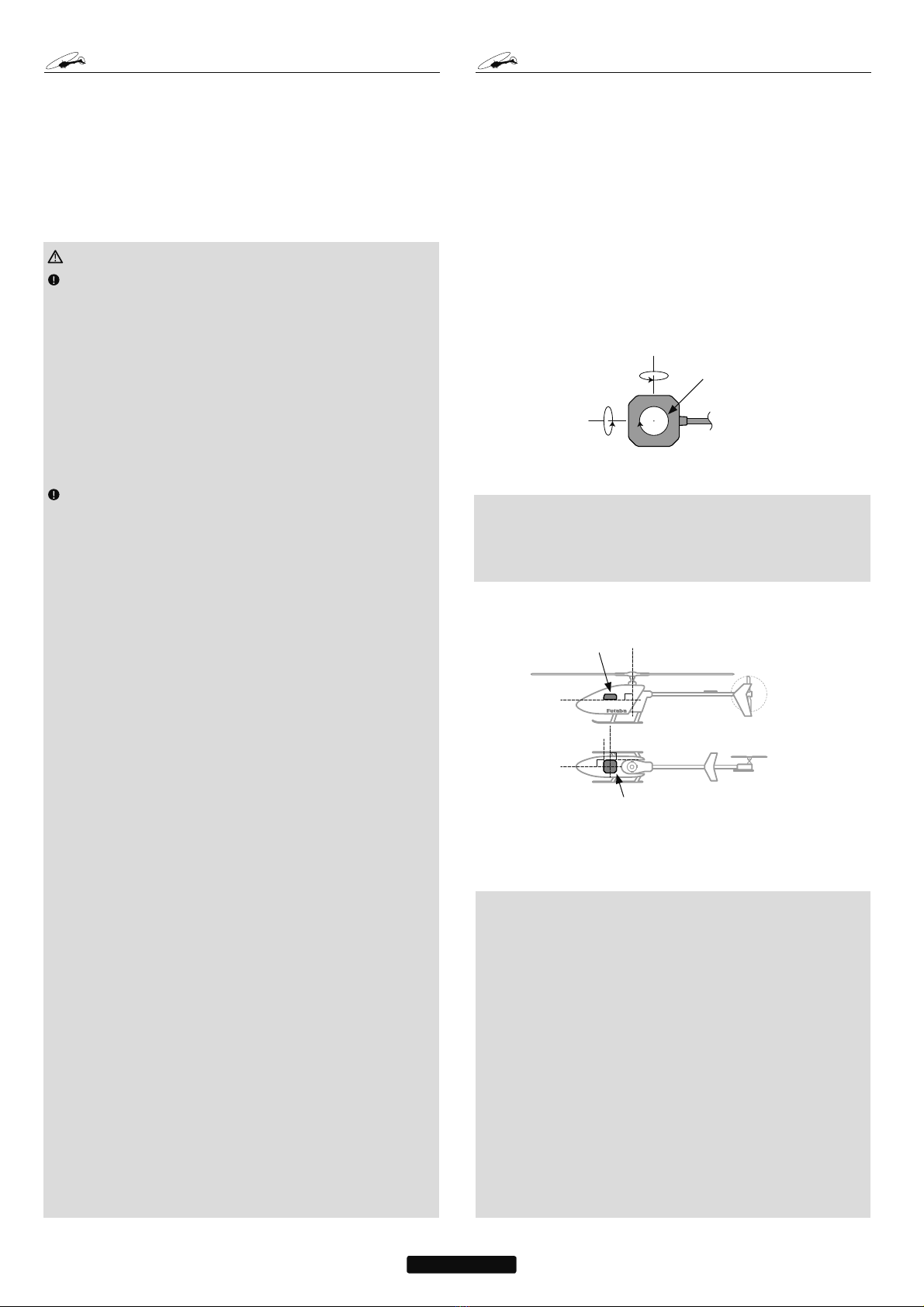
Gyro operating precautions:
Gyro
The CGY750 requires 5-10 seconds to initialize when the power
is turned on. Do not move the helicopter and do not move the tail
rotor, aileron and elevator sticks during this initialization or the
gyro may not initialize properly. Once the initialization process
has been completed the swash servos and tail servo will move
several times indicating that the CGY750 is now ready for flight.
Verify that the gyros are operating and compensating in the correct
direction before each flight. If the compensation direction is incorrect
on any axis the model will become uncontrollable after takeoff.
Verify that the gyro is operating in the desired mode.
Verify that the gyro mounting pads are in good condition.
Verify that the gyro wires are not contacting the frame of the heli-
copter.
The servo type parameters within the CGY750 must match the type
of servo you are using. Incorrect setting may damage the CGY750 or
the servos, possibly resulting in a loss of control during flight.
Always ensure that there is some slack in the gyro cables to help
maximize performance. Always use the supplied gyro mounting pads
to attach the gyro to the helicopter mechanics. Do not use a strap that
encompasses the CGY750 sensor. This may affect the overall perfor-
mance of the gyro.
Always allow the gyro to adjust to the surrounding environmental
temperature before flight. A large temperature change during use will
cause drift and other operational issues.
The gyro sensor and control box have a electroconductive coating.
Do not allow any power leads or other wiring to come into contact with
these items.
If you are switching between Normal Mode and AVCS Mode in
flight, please keep in mind that you must have the gyro re-learn the
center position after making a trim change within the transmitter.
To memorize the new center position simply flip the gain switch on
the transmitter three times between Normal Mode and AVCS Mode
(NormaltAVCStNormaltAVCS) within one second. The servo will
center indicating that the new center position has been memorized.
When operating the gyro in AVCS Mode, all compensation and
revolution mixing must be disabled and any tail rotor or swash offsets
for flight modes must be disabled.
When the CGY750 is operated in AVCS mode the tail rotor or
swashplate servos will not center when tail rotor, aileron or rudder
stick is released. This is normal operation for AVCS mode. The servos
PRECAUTIONS
may also move to the extent while the model is being carried out to the
flight line. Before take off, you must visually center the tail rotor pitch
slider and level the swash plate by using the transmitter control sticks.
You can also center the servos by moving the tail rotor stick full left, then
full right, back to full left and then allow the stick to center within one
second; the same method applies for aileron and elevator servos.
Do not drop the CGY750 sensor onto a hard surface or subject the
CGY750 sensor to a strong shock as this may damage the sensor.
Always use the supplied mounting pads or the Futaba replacement
mounting pads available from your local Futaba dealer.
Governor operating precautions:
Governor
When the throttle servo is connected to the CGY750, the battery fail-
safe function within the CGY750 must be setup and enabled.
Throttle fail safe function (transmitter setting): Use the fail safe func-
tion for the channel that turns the governor on and off to set the fail safe
position to the point at which the governor is turned off. With this setting,
when the system enters the fail safe state, the governor will be turned
off, and the receiver throttle signal (fail safe position preset) will be out-
put directly.
When using the condition hold function on the transmitter, always
set the throttle servo maximum operating point to less than the point at
which the governor is activated. If this is not done the governor may ac-
tivate while in condition hold.
While preparing for flight or starting the engine, always ensure the
throttle remains below the governor activation point and do not select
any flight modes that may activate the governor.
If you prefer to activate the governor while the model is still on the
ground, always ensure that you have at least -5 degrees of pitch in the
model before activating the governor. This negative pitch is necessary
to prevent an unexpected lift off as the governor activates and the head
speed increases to the desired RPM.
Periodically check the RPM sensor output to ensure proper governor
operation. Due to the high level of vibration and centrifugal forces the
magnet may come loose or the sensor alignment may change. Every
10th flight verify that the magnet and sensor are properly mounted.
Width (Controller): LQ>PP@
(Gyro sensor): LQ>PP@
(Revolution sensor): LQ>PP@
Length (Controller): LQ>PP@
(Gyro sensor): LQ>PP@
(Revolution sensor): LQ>PP@
Height (Controller): LQ>PP@
(Gyro sensor): LQ>PP@
(Revolution sensor): LQ>PP@
Weight (Controller): R]>J@
(Gyro sensor): R]>J@
(Revolution sensor): R]>J@
Operating Voltage
: 9WR9'&
Current Drain: P$
Selectable Servo Frame:
+]+]DQG+]
5XGGHU*\URRQO\5DWH
Center Pulse Width:
6+]+]
ȝV+]
Governor Resolution: +]USP
(QJLQH530
RPM Accuracy:
Head Speed Range: USP
Operating Temperature: )WR)
&WR&
Control System: 'LJLWDODGYDQFHGFRQWURO
Sensor:
0LFUR(OHFWURPHFKDQLFDO
6\VWHPV0(06*\UR
+DOOHIIHFWVHQVRU
Angular Velocity Range: 'HJUHHV3HU
6HFRQG*\UR
7KHRSHUDWLQJYROWDJHVKRZQRQO\DSSOLHVWRWKH&*<$OZD\VYHULI\WKDW
\RXUUHFHLYHUVHUYRVWDLOURWRUVHUYRVZLWFKDQGDQ\RWKHUHOHFWURQLFFRPSR-
QHQWVXVHGLQ\RXULQVWDOODWLRQDUHFDSDEOHRIRSHUDWLQJDWWKHYROWDJH\RXSODQ
WRXVH
SPECIFICATIONS

4
REPLACEMENT & OPTIONAL ITEMS
Futaba PC Interface CIU-2: FUTM0951
Extension 200 mm:
Extension 350 mm:
Extension 55 mm:
Extension 80 mm:
Extension 130 mm:
Mounting Pad:
1x22x22 mm (10)
WARNING
Newer high end servos and other radio equipment
are capable of placing large demands on the power
systems in use today. When using a regulator you
must ensure that the regulator is capable of supply-
ing the current demands of the equipment you have
selected. In addition to this make sure the wiring
and switch you have selected are capable of han-
dling high current draws.
• The servo current draw can be up to 50% higher on a flybar-
less helicopter. Always ensure your receiver battery is fully
charged before each flight.
Even though the CGY750 is a high performance
gyro and governor, it will be necessary to ensure
that the helicopter mechanics are also in optimum
operating condition. Please use the guidelines be-
low and address all issues before installing and fly-
ing the CGY750.
• The CGY750 must be used with a rigid tail rotor drive system.
Any modern torque tube or belt drive system should be ad-
equate. Do not attempt to fly the CGY750 using a wire driven
tail rotor system.
• Always ensure the drive gears, torque tube, pulleys, belt,
bearings and shafts are in proper working condition. If any of
these items are damaged or worn they must be replaced.
•
The linkage rod, tail rotor bell crank, pitch slider and tail rotor
grips must operate without friction to obtain the best perfor-
mance from the CGY750. Binding in the tail rotor control linkage
will decrease the performance of the CGY750 gyro and this may
also shorten the servo lifespan. Please take the time now to en-
sure the tail rotor system on your helicopter is working correctly
and without friction or binding.
• Vibration will affect the CGY750’s overall performance. All
rotating components on the helicopter should be balanced
to minimize vibrations in flight. Ensure that your engine or
electric motor is running smoothly and that all vibrations have
been addressed before installing and test flying the CGY750.
Gyro sensor replacement:
• Each CGY750 gyro control box is calibrated specifically for
the gyro sensor included. Do not attempt to use another
CGY750 sensor with the control box as performance will suf-
fer due to being out of calibration. The calibration process
must be completed by an authorized service center.
If your sensor needs replacement, please send the complete
unit to your region’s support center for repair.
7KH J\UR VHQVRU VKRXOG EH PRXQWHG RQ D ULJLG SODWIRUP DW OHDVWLQ
>PP@ DZD\ IURPD1LWUR(QJLQH,WLVQRWQHFHVVDU\WRPRXQW
WKHJ\URQHDUWKHPDLQVKDIWRIWKHKHOLFRSWHUEXWLWLVYHU\LPSRUWDQW
WKDWWKHPRXQWLQJDUHDFKRVHQLVULJLG3OHDVHUHIHUWR\RXUKHOLFRSWHU
PDQXIDFWXUHU¶VLQVWUXFWLRQVIRUUHFRPPHQGHGPRXQWLQJORFDWLRQV
7HVW¿WWKHJ\URVHQVRUHQVXULQJWKDWWKHVHQVRULVLQDOLJQPHQWZLWK
WKHKHOLFRSWHURQWKHUROODQGSLWFKD[LV7KHFDEOHIURPWKHJ\URVHQ-
VRUPXVWH[LWWRZDUGWKHIURQWRUWKHUHDURIWKHKHOLFRSWHUVLQFHWKLVLV
WKHSLWFKD[LV$Q\PLVDOLJQPHQWZLOOFDXVHDORVVRISHUIRUPDQFH
2QFH\RXDUHFHUWDLQHYHU\WKLQJLVSURSHUO\DOLJQHGDQGWKDWWKHVHQVRU
OHDGFDQ EH URXWHG WRWKH J\UR JRDKHDG DQG PRXQWWKHJ\UR VHQVRU
WRWKHKHOLFRSWHUXVLQJRQHRIWKHVXSSOLHGJ\URSDGV5RXWHWKHJ\UR
VHQVRUOHDGWRWKH&*<FRQWUROER[DQGSOXJWKHOHDGLQWRWKHJ\UR
VHQVRUSRUW9HULI\WKDWWKHFRQQHFWRULV¿UPO\ORFNHGLQSODFH
Gyro Sensor
• Elevator (Pitch) axis
• Rudder (Yaw) axis
• Aileron (Roll)
axis
GYRO SENSOR INSTALLATION
Important: The CGY750 gyro sensor must be mounted so that the
roll and pitch sensing axis are in alignment with the helicopter. Any
misalignments over 1/2 of a degree will cause a loss in performance.
Please take extra care in this step to ensure the optimum flight perfor-
mance.
TROUBLESHOOTING
If any issues are noted during flight (such as drifting, inconsistent hold
or inconsistent control rates) then please review the following trouble-
shooting recommendations.
1. Always verify that the tail rotor and swash plate mechanisms oper-
ate, and that the drive system is in proper working order.
2. Electromagnetic interference could be causing the problem. If you
feel everything is set up correctly and that the helicopter is vibration
free, then consider moving the gyro sensor to a new location away
from servos, ESC and drive motors.
3. Vibrations will decrease the performance of all gyro systems. Even
though the CGY750 gyro sensor is the most vibration resistant gyro
sensor available, eliminating vibrations will always improve perfor-
mance. The CGY750 gyro sensor performs best when the sensor is
mounted rigidly to the airframe. This is mainly due to the sensing of
all 3 axes. It is highly recommended to avoid using soft foam pads
as this may allow the gyro to bounce around on the roll and pitch
axis, causing instabilities and possible loss of control during flight.
• The bottom of the CGY750 Gyro
Sensor must be perpendicular to
the main shaft.
• The roll axis must be parallel to
the tail boom and the pitch axis
must be perpendicular to the side
frame.

5
OLED Display
• Displays menus, parame-
ters and status information.
Edit Keys
• Used when setting data.
• Use the included plastic ad-
justment screwdriver to press
the buttons.
C
ONNECTING THE
CGY750
Connection to the receiver, servos and sensors
7KH &*< UHTXLUHV DQ 6%86 UHFHLYHU RU WKH RSWLRQDO 3:0 5H-
FHLYHUWR6%86DGDSWHUDYDLODEOHVHSDUDWHO\
8VLQJWKHVXSSOLHGH[WHQVLRQFRQQHFWWKH6%86UHFHLYHUSRUWRUIURP
WKH 6%86 3:0 DGDSWHU WR WKH &*< 6%86 SRUW ,QVWDOO \RXU
UHFHLYHUEDWWHU\UHJXODWRUVZLWFKDQGDQ\RWKHUQHFHVVDU\HOHFWURQLFV
QRZ&RQQHFWWKHSRZHUOHDGRI\RXUVZLWFKUHJXODWRUWRWKHEDWWHU\
FRQQHFWRURQWKHUHFHLYHU
3OXJ WKH F\FOLF VHUYRV $,/>$LOHURQ@ (/(>(OHYDWRU@ 3,7 >3LWFK@
58'>7DLO5RWRU@DQGLIXVLQJ WKH+[[VZDVKSODWHW\SH7+(
>(OHYDWRU@LQWRWKHDSSURSULDWHSRUWRQWKH&*<
'HWHUPLQHWKHEHVWORFDWLRQWRSODFHWKHUHFHLYHUDQG&*<FRQWURO
ER[0RXQWWKHUHFHLYHUDQGWKH&*<FRQWUROER[WRWKHKHOLFRS-
WHUPHFKDQLFVXVLQJYLEUDWLRQDGVRUELQJVHOIDGKHVLYHIRDPSDGV7KH
&*<J\URVHQVRUZLOOEHLQVWDOOHGLQDODWHUVWHS
8VLQJZLUHPRXQWVZLULQJ¿[WXUHVPROGHGLQWRWKHKHOLFRSWHURUKRRN
DQGORRSPDWHULDOURXWHWKHVHUYROHDGVDQGH[WHQVLRQV0DNHVXUHWKH
ZLUHVDUHQRWUXEELQJDJDLQVWPHWDORUFDUERQ¿EHUZKLFKPD\GDPDJH
WKHZLUHV
S.BUS channel setting
6LQFH WKH 6%86 SURWRFRO XVHV D VLQJOH ZLUH WR WUDQVPLW DOO FKDQQHO
LQIRUPDWLRQWR WKH&*<LWLVQHFHVVDU\WRDVVLJQHDFKFKDQQHO
QXPEHU WKURXJK D IXQFWLRQ VXFK DV DLOHURQ SLWFK FROOHFWLYH
JDLQ DLO JDLQ HOH JDLQ USP JY RQRII ZLWKLQ WKH &*< FRQWURO
ER[7KH GHIDXOW&*<6%86 FKDQQHODVVLJQPHQWV VKRXOGZRUN
SURSHUO\ ZLWK PRVW )XWDED WUDQVPLWWHUV ,I \RX H[SHULHQFH DQ\ SURE-
OHPVSOHDVHUHIHUWRWKH6%86VHFWLRQRIWKHPDQXDOWRVHWYHULI\HDFK
FKDQQHOQXPEHUIRUHDFKIXQFWLRQ
,I \RXU WUDQVPLWWHU GRHV QRW RIIHU HQRXJK FKDQQHOV WR RSHUDWH DOO RI WKH
&*<¶V IXQFWLRQV LW LV SRVVLEOH WR RSHUDWH WKH &*< ZLWKRXW WKH
*92Q2II$LO*DLQDQG(OH*DLQFKDQQHOVFRQQHFWHG:KHQDQ\WKHVH
IXQFWLRQVDUHQRWXVHGLWLVQHFHVVDU\WRVHWWKHFKDQQHOQXPEHUWR>,1+@
ZLWKLQWKH&*<¶V6%86PHQXWRGLVDEOHWKHIXQFWLRQDQGWRXVHWKH
VHWWLQJYDOXHLQVLGHWKH&*<PHQXLQVWHDG
:KHQWKH*92Q2IIFKDQQHOLVQRWXVHGWKHJRYHUQRURQRIIFRQWUROLV
KDQGOHGE\WKH>6WLFN6ZLWFK@IXQFWLRQ
:KHQ WKH UHPRWH$LO RU (OH *DLQ FKDQQHOV DUH QRW XVHG WKH RSHUDWLQJ
PRGH 125$9&6 DQG JDLQ YDOXH FDQ EH VHW LQ WKH DSSURSULDWH$,/
(/(%DVLFPHQXRSWLRQE\XVLQJWKH'DWDNH\VZKHQWKHIXQFWLRQLV
GLVSOD\HG
Using the CGY750 with a electric helicopter
DANGER
It is necessary to remove the pinion gear from the electric motor
or disconnect the motor from the ESC before powering the model
up for setup or bench testing. Electric motors are extremely pow-
erful and capable of delivering the power instantly, causing injury
to yourself, others, or the surroundings.
,I WKH &*< LV EHLQJ LQVWDOOHG LQWR DQ HOHFWULF KHOLFRSWHU DQG WKH
(6&¶VRZQLQWHUQDOJRYHUQRULVWREHXVHG\RXPD\ZDQWWRFRQVLGHU
FRQQHFWLQJWKH(6&WRWKH>7+(@WKURWWOHHOHYDWRURXWSXWRIWKH
&*< %HIRUH GRLQJ WKLV \RX PXVW UHPRYH WKH SLQLRQ JHDU IURP
WKHHOHFWULFPRWRURUGLVFRQQHFWWKHPRWRUIURPWKH(6&EHIRUHSRZHU-
LQJWKHPRGHOXSWKH¿UVWWLPH2QFHWKHPRGHOKDVEHHQSRZHUHGXS
QDYLJDWHWRWKHJ\URPRGHIXQFWLRQDQGVHWLWWR>*<527+5@7KLV
VHWVWKH &*< WRDFW DV DJ\UR DQG WKURWWOHRXWSXW 7KH &*<
ZLOO VLPSO\ SDVV WKH WKURWWOH VLJQDO IURP WKH UHFHLYHU WKURXJK WR WKH
7+(SRUWRQWKH&*<
2QFH\RXU (6&LV FRQQHFWHGWR WKH&*< \RXPXVWFRPSOHWHDOO
QHFHVVDU\WUDQVPLWWHUVHWXS$79(3$5(9(7&SHU\RXU(6&
LQVWUXFWLRQV3OHDVHUHIHUWRWKH HQGRIWKLV PDQXDOIRU IXUWKHU VXJ-
JHVWLRQVIRUWKHXVHRIWKH&*<¶VJRYHUQRUZLWKHOHFWULFSRZHUHG
PRGHOV
(1) Gyro Sensor:
• Connect the gyro sensor.
*Insert the sensor connector until it is
firmly locked.
(2)
Rsen (Revolution sensor)
:
• Connect the revolution sensor.
(3) S.BUS:
• Connect to the S.BUS output of the
receiver with the supplied extension.
(4) AIL Output:
• Connect the aileron servo.
(5) ELE Output:
• Connect the elevator servo.
(6) PIT Output:
• Connect the pitch servo.
(7) TH Output:
• Connect the throttle servo.
• Connect the ESC w/BEC and set the
operation mode to Gyro+THR mode.
(7) E2 2nd ELE Output:
• Connect the second elevator servo.
(Swash mode: H4-00 or H4-45)
(8) RUD Output:
• Connect the rudder servo.
(1)
(2)
(3)
(4)
(5)
(6)
(7)
(8)
7KLVGLDJUDP VKRZVWKHYDULRXVFRQ-
QHFWLRQVEHWZHHQWKH&*<DQG
UHFHLYHUVHUYRRUVHQVRUV
,IWKHJRYHUQRUDQGOLPLWHUIXQFWLRQVDUH
GLVDEOHG ZKHQ XVLQJ WKH >*\UR7+5@
PRGHWKHQWKHWKURWWOHVLJQDOLVVHQW
GLUHFWO\WRWKH7+(FRQQHFWLRQRQWKH
&*<,QWKLVFDVH\RXPD\FRQQHFW
WKHWKURWWOHVHUYRWRWKHDSSURSULDWH
FKDQQHORQ WKH UHFHLYHURUWR WKH &*<
7+(FRQQHFWRU
:KHQ WKH VZDVK PRGH LV VHW WR +[[
PRGHWKH7+WHUPLQDOLVFKDQJHGWR
QGHOHYDWRURXWSXW,QWKLVFDVHWKH
JRYHUQRUIXQFWLRQLVLQKLELWHG
WARNING
You will feel resistance at two points
when inserting the connector. Make sure
that you plug in the connector completely,
or connection problems may result.
Installing the Sensor Connector
1) First resistance (incomplete
connection)
Locking tab
2) Second resistance (fully
connected)
Ɣ&RQWLQXHSXVKLQJWKHFRQQHF-
WRUXQWLO\RXKHDUWKHORFNLQJWDE
³FOLFN´
H-1
SwashType
Yourtransmitter
shouldbereset
tothedefault
settingsandthe
swashplatetype
selectedwiththe
transmittershould
besettoNormal
(H-1)orsingle
servomode.All
CCPMmixingissetupandhandled
withtheCGY750,andthetransmitter
functionsshouldnotbeused.Before
startinghelicopterset-up,besure
thatalldualrates,pitchcurve,and
endpointvaluesaresetto100/100.

6
GOVERNOR INSTALLATION
0RGLI\WKHFRROLQJIDQDQGLQVWDOOWKHDFFHVVRU\PDJQHWDQGDWWDFKWKH
PDJQHWLF VHQVRU WR WKH HQJLQH DW WKH SRVLWLRQ VKRZQ EHORZ %DODQFH
WKHFRROLQJIDQDVQHHGHGIROORZLQJPDJQHWLQVWDOODWLRQ
Cooling fan
Magnet (Embedded in cooling fan.)
Sensor (Attached to engine flange
through a stay.)
:KHQLQVWDOOLQJWKHVHQVRUPDJ-
QHWWRWKHPXIÀHUVLGHDOVRUHIHU
WRWKHQHHGOHVLGHPRXQWLQJ
Magnet operating side check
%ULQJWKHPDJQHWQHDUWKHHQGRIWKHVHQVRUDQGFKHFNWKHRSHUDWLQJVLGH
Magnet
Sensor
7KLVLVWKHVLGHDWZKLFKWKHGLVSOD\HGYDOXHLQFUHDVHVLQWKH³5HYROXWLRQ
VHQVRUWHVWLQJ´PHQXZLWKLQWKH³Governor Basic Setting´VHFWLRQHDUOLHU
LQWKLVPDQXDO,QVWDOOWKHPDJQHWZLWKWKLVVLGHIDFLQJWKHVHQVRU0DUN
WKLVVLGHRIWKHPDJQHWZLWKDIHOWWLSSHQ
&RROLQJIDQPRGL¿FDWLRQ
'ULOO D KROH LQ WKH IDQ DW WKH PDJQHW PRXQWLQJ SRVLWLRQ 0DNH WKH KROH
DERXWPPLQGLDPHWHUDQGWRPPGHHS
(PEHGWKHPDJQHWLQWKLVKROHLQWKHGLUHFWLRQLQZKLFKDQRXWSXWLVRE-
WDLQHG8VHHSR[\DGKHVLYHWKDWFXUHVLQPLQXWHVRUORQJHU'RQRWXVH
HSR[LHVWKDWFRQWDLQPHWDOVXFKDV-%:HOG
Magnet
Cement the magnet to the cooling
fan so that the magnet is level
with this side of the cooling fan.
,IWKHFRROLQJIDQLVXQEDODQFHGDQGYLEUDWHVHWFEDODQFHLWE\PRXQWLQJ
WKHVSDUH PDJQHW WRWKHRSSRVLWH VLGH RIWKHFRROLQJ IDQ LQWKHRSSRVLWH
SRODULW\VRWKDWLWGRHVQRWRXWSXWDVLJQDO
Sensor mounting
7KHVHQVRUPRXQWLQJPHWKRGGHSHQGVRQWKHKHOLFRSWHUDQGHQJLQH
0RXQWWKHVHQVRUWRWKHVHQVRUVWD\7HPSRUDU\DVVHPEO\
'ULOO D KROH LQ WKH IDQ FRYHU DW WKH SDUW FRUUHVSRQGLQJ WR
WKHVHQVRUVRWKDWWKHGLVWDQFHEHWZHHQWKHVHQVRUDQG
PDJQHWFDQEHPDGHWRPP
7LJKWHQWKHVHQVRUVWD\WRJHWKHUZLWKWKHHQJLQHPRXQWLQJ
ÀDQJH7HPSRUDU\DVVHPEO\
6HOHFWWKH PRXQWLQJ PHWKRG VRWKDWWKHVHQVRUGRHVQRW
WRXFKWKHIUDPHRURWKHUSDUWVRIWKHKHOLFRSWHU7HPSRUDU-
LO\PRXQWWKHVHQVRUDQGVHOHFWWKHPDJQHWPRXQWLQJSRVL-
WLRQ
,QVWDOO WKH VHQVRU WR WKHVHQVRUVWD\XVLQJWKHDFFHVVRU\
VFUHZVDQGZDVKHUV
7LJKWHQWKHVHQVRUVWD\WRJHWKHUZLWKWKHHQJLQHXVLQJWKH
HQJLQHPRXQWVFUHZ
Sensor adjustment
$GMXVWWKHVHQVRUSRVLWLRQWRREWDLQDVHQVRURXWSXWRIDWOHDVWLQWKH
“Revolution sensor testing” PHQXZLWKLQWKH³Governor Basic Setting´
1-2mm
Magnet
Sensor
2.2
mm
3.7mm 3.7mm
Center of sensor
is offset.
Sensor
case
7KHFHQWHURIWKHVHQVRULVGLIIHUHQWIURPWKHFHQWHURIWKHVHQVRUFDVHVR
EHFDUHIXOZKHQPRXQWLQJWKHVHQVRU
,IWKHGLVSOD\LVOHVVWKDQ ZKHQWKHPDJQHWLVGLUHFWO\EHORZWKH
VHQVRUEULQJWKHVHQVRUFORVHUWRWKHPDJQHWVRWKDWWKHRUPRUHLV
GLVSOD\HG7KHPDJQHWDQGVHQVRUJDSFULWHULDLVDSSUR[LPDWHO\WRPP
,IDVHQVRURXWSXWLVQRWREWDLQHGHYHQZKHQWKHVHQVRULVEURXJKWFORVHWR
WKHPDJQHWWKHPDJQHWDQGVHQVRUFHQWHUSRVLWLRQVPD\KDYHFKDQJHG
&RPSOHWHDVVHPEO\RI WKH VHQVRUE\VHFXUHO\ WLJKWHQLQJ WKHVFUHZV WKDW
ZHUHWHPSRUDULO\WLJKWHQHG
5HFKHFNWKHVHQVRURXWSXW
GOVERNOR FUSELAGE SETTING PRECAUTIONS
Throttle servo linkage precautions
7RHIIHFWLYHO\XVH WKHJRYHUQRUREVHUYH WKHIROORZLQJSUHFDXWLRQV
ZKHQFRQQHFWLQJWKHVHUYROLQNDJH
0DNHWKHVHUYRRSHUDWLQJUDQJHDVZLGHDVSRVVLEOH0DNHWKHWKURZRI
WKHWUDQVPLWWHU(3$$79IXQFWLRQDQG$)5IXQFWLRQDVFORVHDVSRVVLEOH
WR
)O\ZLWKWKHJRYHUQRUWXUQHG2))DQGDGMXVWWKHQHHGOHVRWKDWWKHHQJLQH
VPRRWKO\UHDFWVWRPRYHPHQWRIWKHWUDQVPLWWHUVWLFN
,IWKHUHLVDSRLQWDWZKLFKWKHUHDFWLRQRIWKHHQJLQHLVFRQVLGHUDEO\GLI-
IHUHQWGXHWRDWRRULFKRUWRROHDQPL[WXUHWKHJRYHUQRUPD\QRWRSHUDWH
WRLWVPD[LPXPSRWHQWLDO
Fuselage vibration countermeasures
,IWKHKHOLFRSWHUIUDPHLVZHDNRUWKHHQJLQHPRXQWLVGHIRUPHGRUQRW
LQVWDOOHGSURSHUO\WKHYLEUDWLRQV DSSOLHGE\WKH HQJLQHZLOOLQFUHDVH
(QJLQHYLEUDWLRQVZLOOOHDGWRXQVWDEOHVSHHGDQGSUHYHQWWKHJRYHUQRU
IURPSURYLGLQJPD[LPXPSHUIRUPDQFH7KHUHIRUHPDNHVXUHWKDWWKH
HQJLQHLVYLEUDWLRQIUHHDQGWKDWWKHFDUEXUHWRUSURYLGHVOLQHDUWKURWWOH
FRQWUROEHFDXVHWKHJRYHUQRUFDQQRWFRUUHFWHQJLQHSUREOHPV
Use of a tuned silencer
7KH XVH RI D WXQHG SLSH W\SH VLOHQFHU PD\ FDXVH WKH HQJLQH WKURWWOH
UHVSRQVH WR EH VXEVWDQWLDOO\ GLIIHUHQW IURP WKDW RI D QRUPDO PXIÀHU
$GMXVWWKHQHHGOHDQGSLSHOHQJWKVRWKDWHQJLQHVSHHGFKDQJHVDUH
SURSRUWLRQDO WR WKH WKURWWOH RSHQLQJ 7KH JRYHUQRU ZLOO QRW SHUIRUP
VDWLVIDFWRULO\ZLWKDPXIÀHURUDSLSHWKDWGRHVQRWDOORZWKHFDUEXUH-
WLRQWREHOLQHDU
TX SET-UP
Condition selection
&RQGLWLRQVHOHFWLRQLQFRUSRUDWHVWZRDGMXVWDEOHYDOXHVIRUD JLYHQ
SDUDPHWHUGLVSOD\HGFF7KLV LVGLFWDWHGE\ WKHGLJLWDOFKDQQHO
QXPEHU³´ZLWKLQWKH)XQFWLRQ0HQXRI\RXUWUDQVPLWWHU'*$V-
VLJQLQJ'*WRDVZLWFKRUÀLJKWPRGHDOORZVWKHXVHRIWZRVHSDUDWH
YDOXHVIRUWKHFRQGLWLRQVHOHFWDEOHSDUDPHWHUV
Rotor Head Gyro Gain “RotHd.Gn”
,QWKH6%86PHQXDVVLJQLQJ³5RW+G*1´WRDFKDQQHOZLOODOORZWKH
5RWRUKHDGJDLQWREHDGMXVWHGYLDWKH7;,I\RXDUHXVLQJD&+RU
OHVV7;VHWWLQJ³5RW+G*Q´WR³,1+´ZLOOWKHQGHIDXOWWKHJDLQWR
³%DVH*DLQ´LQWKH)OLJKW7XQLQJPHQX6XJJHVWHGVHWWLQJDQGGHIDXOW
LV&+
Tail Rotor Gain “RGn”
,QWKH6%86PHQXDVVLJQLQJ³5*Q´WRDIUHH7;FKDQQHOZLOODOORZ
IRUWKHWDLOURWRUJDLQWREHDGMXVWHGYLDWKH7;6XJJHVWHGVHWWLQJDQG
GHIDXOWLV&+
NOTE - Before starting helicopter set-up, be sure that
all dual rates, pitch curve, and endpoint values are set
to 100/100.
Governor
Governor

7
OPENING SCREEN Home SCREEN
9HULI\WKDWDOORIWKHFRQQHFWLRQVDUHFRUUHFWEHWZHHQWKH&*<UH-
FHLYHUDQGSRZHUVXSSO\,I\RXUKHOLFRSWHULVXVLQJDQHOHFWULFPRWRU
IRUSURSXOVLRQUHPRYHWKHSLQLRQJHDUQRZIRUVDIHW\
,IWKLVLVWKH¿UVWWLPHWKHKHOLFRSWHUKDVEHHQSRZHUHGXSUHPRYHWKH
VHUYRDUPVDQGOLQNDJHVWRSUHYHQWGDPDJLQJWKHVHUYRVLIDQ\ELQGLQJ
LV SUHVHQW 3RZHU XS WKH WUDQVPLWWHU DQG DOORZ LW WR LQLWLDOL]H 7XUQ
WKHUHFHLYHURQRUFRQQHFWWKHÀLJKWEDWWHU\DQGDOORZWKHKHOLFRSWHUWR
UHPDLQPRWLRQOHVVZKLOHWKH&*<LQLWLDOL]HV
7KH GLVSOD\ ZLOO ¿UVW VKRZ WKH ,' QXPEHU RI \RXU &*< DQG WKH
)LUPZDUH9HUVLRQ
$IWHUWKH&*<KDVSRZHUHGXSWKHVFUHHQZLOOFKDQJHWRVKRZDQ
DQLPDWLRQRIDKHOLFRSWHUSHUIRUPLQJDVWDWLRQDU\ÀLS7KLVLQGLFDWHV
WKDWWKHLQLWLDOL]DWLRQ SURFHVVLVWDNLQJSODFH7KHKHOLFRSWHUPXVWUH-
PDLQ SHUIHFWO\ VWLOO VR WKH FRQWUROOHU FDQ GHWHUPLQH WKH J\UR¶V FHQWHU
SRVLWLRQIRUHDFKD[LV
2QFHWKH LQLWLDOL]DWLRQSURFHVV KDVEHHQ FRPSOHWHGWKH +RPH6FUHHQ
ZLOOEHGLVSOD\HGDQGWKHF\FOLFWDLOURWRUVHUYRVZLOOPRYHVHYHUDO
WLPHVLQTXLFNVXFFHVVLRQ
,IWKH&*<LVVHWWRWKH>*\UR7+5@PRGHRULIWKH+[[VZDVK
SODWHW\SHKDVEHHQVHOHFWHGWKHQWKHJRYHUQRUZLOOEHGLVDEOHGDQGWKH
VFUHHQZLOOORRNOLNHGEHORZLQVWHDG7KHGLVSOD\ZLOOF\FOHWKURXJK
DQGVKRZWKHFXUUHQW$,/(/(DQG58'JDLQV
Initial Home screen
1. Axis indication 2. Gyro operation mode
3. Gyro gain
4. on/off switch
5.Yaw rate comp
7. Setting Menus
6. Battery voltage
(b) Aileron gain
display
(c) Elevator gain
display
(d) Gyro only
mode
1. Axis indicator
Gyro
7KH D[LV LQGLFDWRU ZLOO F\FOH HYHU\ WZR VHFRQGV DQG VKRZ WKH D[LV $,/
(/(RU58'DQGWKHLUUHVSHFWLYHFXUUHQWJDLQYDOXHV
2. Gyro operation mode
Gyro
7KHGLVSOD\LQGLFDWHVHLWKHU>$@IRU$9&6RU>1@IRU1RUPDORSHUDW-
LQJPRGHV ,IWKH >$@LV VKRZQ LQLQYHUWHG FRORUVWKHQWKH UXGGHU
QHXWUDOLVRIIVHWDQGUHOHDUQLQJWKHFHQWHUSRVLWLRQVKRXOGEHFRP-
SOHWHGLPPHGLDWHO\
RUD AVCS Mode
at 100% gain
RUD NOR Mode
at 100% gain
Neutral offset at
AVCS mode
:KHQXVLQJ WKH$9&6RSHUDWLQJPRGH WKHVHUYRV ZLOO QRW UHFHQWHU ZKHQ
WKHFRQWUROVWLFNLVUHOHDVHG,I\RXQHHGWRFHQWHUWKHVHUYR\RXFDQPRYH
WKH DSSURSULDWH FRQWURO VWLFN WR LWV IXOO H[WHQW OHIW ULJKW RU XS GRZQ
WZLFHDQGDOORZWKHFRQWUROVWLFNWRUHWXUQWRFHQWHUZLWKLQDRQHVHFRQGSH-
ULRGRIWLPHDQGWKHVHUYRVIRUWKDWD[LVZLOOUHWXUQWRFHQWHUSRVLWLRQ
Home screen
Push DATA
+/– key
Push DATA
+/– key
Push MODE
+/– key
Thick line
shows MODE.
Maximum
RPM
Condition#
indication
Engine
runtime
OLED
Setting
Maximum
Roll Rate
Maximum
elevator rate
Push DATA
+/– key
Thin line
shows DATA.
Push MODE +/– key
for 1 second
Swash
Flight Tuning Expert
Gyro (RUD)
Governor
FIRST MAP
Rudder gain display
The figure shows the first layer of the editing
sequence.
Condition
Menu
CondData
Cond.1
WhenCondMenuisON,this
changesintoCondMenu.

8
)RUH[DPSOHLI\RXPRYHWKHWDLOURWRUVWLFNIXOOOHIWIXOOULJKWIXOOOHIWIXOO
ULJKWDQGDOORZLWWRFRPHEDFNWRFHQWHUZLWKLQRQHVHFRQGWKHQWKHGLVSOD\
ZLOOFKDQJHWRVKRZ>@DQGWKHWDLOURWRUVHUYRZLOOFHQWHU
3. Gyro gain
Gyro
7KLVLQGLFDWHVWKHFXUUHQWJ\URJDLQIRUWKHD[LVQRWHGLQWKH$[LV,QGLFDWRU
SRVLWLRQ
4. Operating condition
Governor
7KLVLQGLFDWHVZKHWKHUWKHJRYHUQRULV>21@RU>2))@
5. Battery voltage
7KLVLQGLFDWHVWKHEDWWHU\YROWDJH7KHGLVSOD\ZLOOFKDQJHWRVKRZ>/2:%$7@
RQFHWKHYROWDJHKDVIDOOHQEHORZWKH%DWWHU\IDLOVDIHYROWDJHVHWWLQJ%)6
6. Setting Menus
3XVKLQJ WKLV EXWWRQ ZLOO H[LW WKH QRUPDO RSHUDWLQJ PRGH DQG HQWHU WKH VHW-
WLQJVPHQXPRGH
RPM display
Governor
7KHEDWWHU\YROWDJHGLVSOD\DXWRPDWLFDOO\FKDQJHVWRWKHHQJLQH530
GLVSOD\RQFHWKHHQJLQHLVUXQQLQJDQGUHWXUQVWREDWWHU\YROWDJHGLV-
SOD\RQFHWKH HQJLQHKDVVWRSSHGUXQQLQJ7KH530 GLVSOD\FDQEH
HLWKHUWKH KHDGVSHHGRU WKHHQJLQH VSHHGGHSHQGLQJ RQWKHVHWWLQJ
LQ WKH UHYROXWLRQ GLVSOD\ PRGH VHWWLQJ IRXQG LQ WKH JRYHUQRU ([SHUW
PHQX
Home screen options
:KHQWKHKRPHVFUHHQLVVKRZQWKHPRGH>@DQG>@NH\VFDQEHXVHG
WRF\FOHWKHERWWRPOLQHWKURXJKWKHIROORZLQJLWHPV%DWWHU\YROWDJH
0D[530(QJLQHUXQWLPH2/('GLVSOD\RSWLRQV2SHUDWLQJ0RGH
5ROOUDWHPD[LPXPGLVSOD\DQG(OHYDWRUUDWHPD[LPXPGLVSOD\
1. Engine runtime
Governor
)URPWKHKRPHVFUHHQSUHVVWKHPRGH>@NH\WZLFHWRVKRZ WKH HQJLQH
UXQWLPHGLVSOD\7KHWLPHVKRZQLVKRZORQJWKHHQJLQHKDVEHHQUXQQLQJ
7KLVLVDFXPXODWLYHWLPHUDQGWKHYDOXHLVPDLQWDLQHGLQPHPRU\7RUHVHW
WKHWLPHUVLPSO\SUHVVWKHGDWD>@RU>@NH\IRUPRUHWKDQRQHVHFRQGDQG
WKHWLPHUZLOOUHVHWEDFNWR
2. OLED display options [default: Saver]
:KHQWKH >6DYHU@RSWLRQ LV VHOHFWHG WKH GLVSOD\ZLOO GLPDIWHU VHFRQGV
RILQDFWLYLW\2QFHDEXWWRQ LV SUHVVHG RQWKH&*<FRQWUROOHUER[WKH
2/('ZLOOVZLWFKEDFNWRIXOOEULJKWQHVV7KH>6DYHU@RSWLRQKHOSVWRFRQ-
VHUYHSRZHUDQGH[WHQGWKHOLIHRIWKHGLVSOD\:KHQWKH>/LJKW@RSWLRQ LV
VHOHFWHGWKHGLVSOD\ZLOOUHPDLQDWIXOOEULJKWQHVVDWDOOWLPHV
3. Condition menu [default: OFF]
FRQGLWLRQVFDQEHHVWDEOLVKHGSHUSDUDPHWHUE\DVVLJQLQJ&+³'*´WRD
VZLWFKRUÀLJKWPRGH:KHQWKHFRQGLWLRQPHQXLVWXUQHGRQ>&RQG0HQX@
DSSHDUVLQWKHPDLQOLVWRIPHQXV
,W EHFRPHV SRVVLEOH WR KDYH WZR VHSDUDWH YDOXH VHWWLQJV IRU WKH SDUDPHWHUV
OLVWHGLQWKHFRQGLWLRQPHQX
7KHIXQFWLRQVLQFOXGHGLQ>&RQG0HQX@GLVDSSHDUVIURPWKHXVXDOPHQX
4. Roll rate maximum display
Gyro
7KLVVFUHHQGLVSOD\VWKHPD[LPXP UROO UDWH UHFRUGHG GXULQJIOLJKW7KLV
YDOXHLVUHVHWEDFNWRZKHQWKH&*<LVSRZHUHGXS
5. Elevator rate maximum display
Gyro
7KLVVFUHHQGLVSOD\VWKHPD[LPXPHOHYDWRUUDWHUHFRUGHGGXULQJÀLJKW7KLV
YDOXHLVUHVHWEDFNWRZKHQWKH&*<LVSRZHUHGXS
6. Maximum RPM
Governor
)URPWKHKRPHVFUHHQSUHVVWKHPRGH>@EXWWRQRQFHWRVKRZPD[LPXPUH-
FRUGHG530>0USP@7KH>0USP@YDOXHLVPDLQWDLQHGXQWLO\RXFOHDULWE\
SUHVVLQJWKHGDWD>@RU>@NH\IRUDWOHDVWRQHVHFRQG7KLVIXQFWLRQDOORZV
\RXWRFKHFNIRURYHUVSHHGLQJGXULQJÀLJKW
7. Condition #
&XUUHQWFRQGLWLRQLVLQGLFDWHG
WARNING DISPLAY
Governor warning display
Governor
7KHZDUQLQJV\PEROLVGLVSOD\HGZKHQWKHJRYHUQRULVDFWLYDWHGGXU-
LQJSRZHUXS,PPHGLDWHO\VZLWFKWRDFRQGLWLRQWKDWKDVWKHJRYHUQRU
GLVDEOHGDQG WKHV\PERO ZLOOGLVDSSHDU:KHQ WKLVZDUQLQJ V\PERO
LVVKRZQ WKHJRYHUQRU ZLOOEH GLVDEOHGXQWLOWKH ÀLJKWFRQGLWLRQ KDV
EHHQWXUQHGRII7KHHQJLQHPXVWEHVWDUWHGZLWKWKHJRYHUQRUWXUQHG
RII
Sensor Error Gyro
WARNING
The helicopter must remain motionless during the initialization process
or a [SensorER] sensor calibration error may occur.
,IDVHQVRUHUURU RFFXUVGXULQJLQLWLDOL]DWLRQWKH VHQVRULWVHOIPD\EH
GHIHFWLYH
3OHDVHFRQWDFW \RXU UHJLRQ¶VWHFKQLFDO VXSSRUWFHQWHU WKH FRQWDFWLQ-
IRUPDWLRQFDQEHIRXQGLQWKHEHJLQQLQJRIWKLVPDQXDO
Low battery
WARNING
The [Low Batt] warning is displayed if the receiver battery voltage falls
below the [BAT/FS] voltage set within the CGY750 Governor Expert menu.
If this condition lasts for more than one second, then the Battery Fail Safe
function activates, and the throttle servo is brought back to idle position.
This is done to warn you that the battery voltage is dangerously low and that
you must land immediately.
7KHWKURWWOHRSHUDWLRQFDQEH WHPSRUDULO\UHDFWLYDWHGE\ EULQJLQJWKH
WUDQVPLWWHUFRQWUROVWLFNDOOWKHZD\EDFNWRLGOHQRUPDOWKURWWOHIXQF-
WLRQZLOOUHWXUQ$IWHUVHFRQGVWKH%DWWHU\)DLO6DIHIXQFWLRQZLOO
DFWLYDWH DJDLQ UHTXLULQJ \RX WR UHSHDW WKLV SURFHVV LI QHFHVVDU\ 7KH
PRGHOVKRXOGEHODQGHGDVVRRQDVSRVVLEOH
Memory writing indicator
WARNING
Do not power off the CGY750 when the Memory writing symbol is dis-
played.
:KHQ D VHWWLQJ LV FKDQJHG ZLWKLQ WKH &*< WKH QHZ YDOXH PXVW
EH ZULWWHQ WR PHPRU\ 7KH ³0HPRU\ ZULWLQJ LQGLFDWRU´ LV GLVSOD\HG
GXULQJWKLVSURFHVV7KLVSURFHVVPD\WDNHXSWRWZRVHFRQGVDQGWKH
SRZHUPXVWQRWEHVZLWFKHGRIIGXULQJWKLVWLPH
,IWKHSRZHULVVZLWFKHGRIIGXULQJWKHZULWLQJSURFHVVWKHQDOORIWKH
VHWWLQJVPD\EHORVW
Return servo to center position
SETTING MENUS
WARNING
Always exit the Setting Menu and return to the home screen before fly-
ing your model. The gyro operation is disabled within several of the set-
tings menus to ease set up.
Always check the operation of the CGY750, verify that the controls are
operating the correct direction and ensure the gyros are correcting in the
proper direction for all axes prior to attempting to fly the model.
7KH GDWD >@ DQG >@ NH\V DUH XVHG WR QDYLJDWH WKURXJK WKH 6HWWLQJ
0HQXV>58'*\UR@>$,/*\UR@>(/(*\UR@>6:$6+VHW@>*RY-
HUQRU@DQG>6%86@%DVLFPHQXV2QFHWKHGHVLUHGPHQXLVVKRZQ
SUHVVDQGUHOHDVHWKHPRGH>@RU>@NH\WRVKRZWKHQH[WRUVHWWLQJ
LWHPVUHVSHFWLYHO\
7KHH[SHUWPHQXVDUHHQWHUHGRUH[LWHGE\SUHVVLQJDQGKROGLQJWKH
PRGH>@RU>@NH\IRURQHVHFRQG7RH[LWWKHFXUUHQWPHQXVLPSO\
JR EDFN WR WKH %DVLF 6HWWLQJV 0HQX IRU WKH IXQFWLRQ IRU H[DPSOH
>$,/*\UR %DVLF@ DQG SUHVV DQG UHOHDVH WKH PRGH >@ RU >@ NH\
XQWLOWKHKRPHVFUHHQLVVKRZQ
3OHDVHVHH WKH 6HWWLQJ0HQXV GLDJUDPIRU D FRPSOHWHOLVWLQJ RIWKH
+RPH6FUHHQ%DVLFDQG([SHUWPHQXV
7KH>*RYHUQRU@VHWWLQJPHQXLVQRWGLVSOD\HGLIWKH2SHUDWLQJ0RGH
KDVEHHQVHWWR>*\UR7KU@RULIWKHVZDVKSODWHW\SHKDVEHHQVHWWR
WKH+[[W\SH

9
(1) S.BUS connection setting:
start display
Use the mode [+] or [-] keys to
navigate through the menu.
Setting ranges common: 1 ~ 16ch, DG1,
DG2, INH
WARNING
Always verify that the S.BUS function as-
signments match your transmitter’s function
(in the FUNCTION menu) assignments. If any
changes are made within the transmitter func-
tion assignments, then it will also be necessary
to make the changes within the S.BUS function
assignments.
S.BUS BASIC SETTING
6LQFH6%86VHQGVDOOFKDQQHOVPD\EHOLPLWHGE\\RXUWUDQVPLWWHURYHUDVLQJOHZLUHLWLVQHFHVVDU\WRDVVLJQD&*<IXQFWLRQVXFKDV
$,/(/(RU3,7WRHDFKFKDQQHO7KHFKDQQHODVVLJQPHQWVDUHSHUIRUPHGZLWKLQWKH>6%86@%DVLFPHQX
,IDIXQFWLRQLVQRWJRLQJWREHXVHGWKHQLWPXVWEHVHWWR>,1+@)RUH[DPSOHLIWKH5RW+'*QDQG5*1UHPRWHJDLQIXQFWLRQVDUHQRWJRLQJWR
EHXVHGWKHQVHWWKHPWR>,1+@DQGWKH&*<ZLOOWKHQDOORZ\RXWRPDNHJDLQDGMXVWPHQWVZLWKLQWKHUHVSHFWLYHPHQX
S.BUS BASIC MAP
(2) S.BUS setting: Aileron channel [default: 1ch]
Using the data [+] or [-] keys to set the correct channel number.
(3) S.BUS setting: Elevator channel [default: 2ch]
Using the data [+] or [-] keys to set the correct channel number.
(4) S.BUS setting: Throttle channel [default: 3ch]
Using the data [+] or [-] keys to set the correct channel number.
(5) S.BUS setting: Rudder channel [default: 4ch]
Using the data [+] or [-] keys to set the correct channel number.
(6) S.BUS setting: Pitch channel [default: 6ch]
Using the data [+] or [-] keys to set the correct channel number.
(7) Rotor head gain: AIL and ELE gain channel [default: 9ch]
Using the data [+] or [-] keys to set the correct channel number.
(12) S.BUS data reset
This resets the S.BUS channel assignments back to the defaults. Press the data [+] key and [Exec
??] will be displayed as a confirmation. Press data [+] to confirm the reset back to the default set-
tings.
(9) S.BUS setting: RPM channel [default: 7ch]
Using the data [+] or [-] keys to set the correct channel number.
(10) S.BUS setting: GOV. on/off channel [default: 8ch]
Using the data [+] or [-] keys to set the correct channel number.
(8) S.BUS setting: RUD gain channel [default: 5ch]
Using the data [+] or [-] keys to set the correct channel number.
Push DATA
+/– key
Push MODE
+/– key
(11) S.BUS setting: Condition on change channel [default: DG1]
Using the data [+] or [-] keys to set the correct channel number.
NOTE: DG1/DG2 are the C1/C2 recommended channels for changing Condition Data.

10
SWASH BASIC SETTING
7KH>6:$6+VHW@ĺ%DVLFPHQXFRQWDLQVDOORIWKHIXQFWLRQVQHFHVVDU\WRVHWXSWKHVZDVKSODWHVHUYRVDQGWRVHWXSDOOVZDVKSODWHPL[LQJIXQFWLRQV
(1) Start display
The editing menus are
scrolled by pushing the
MODE+ or – key
(5) Swash type [default: H3-120]
Select the swash plate type. Pushing the DATA+ or – key,
display shows the confirmation screen as [Type]? Pushing
the SET key, the type is changed. Pushing the RSET key
or no operation the key for more than 1 second, the display
returns to previous setting. When the type is changed, all
swash parameter are reset.
WARNING
All of the swashplate param-
eters are reset when the swash
plate type is changed. Please
proceed through the entire setup
process before attempting to fly
the model.
WARNING
Read your servo instruction
sheet to determine the proper
servo settings. The servo type
parameter within the CGY750
must match the type of servo
you are using. Incorrect setting
may damage the CGY750 or the
servo. Incorrect setting may also
result in a loss of control during
flight.
WARNING
If the operating mode has been
changed, then the CGY750 must
be reset by powering down and
then powering back up.
(4) Servo type [default: DG:285Hz]
This selects the swash servo types. There are four kinds of
the servo driving frequency selection, AN:70Hz, DG:95Hz,
DG:140Hz, DG285Hz. Previous version supported Analog=
AN: 70Hz and DG:1520= DG:285Hz only. All Futaba digital
servos can be operated with fastest DG:285Hz mode but
some of other brands servos do not support DG:285Hz
mode. In this case, select the proper servo driving frequen-
cy per the manufacturer’s specifications.
(3) Operation mode [default: Gyro+Gov]
This selects the operating mode of the CGY750.
[Gyro+Gov] Both the gyros and the governor are opera-
tional.
[Gyro+THR] The gyro is operational, and the governor is
disabled. The throttle channel from the receiver is passed
through to the [TH/E2] port on the CGY750.
[Gyro+H4] Must be selected when a [H4 xx] swash plate
type is selected. This disables the governor and throttle
servo output and the [TH/E2] port on the CGY750 is now
the second “Elevator” [E2] servo output.
(2) Setup styl [default: 3D]
3D mode contains a proven set of parameters which are
good for not only 3D but also F3C flying. F3C Mode is for
Advanced F3C tuning only.
*The changed menu is indicated on a map.
*When the style is changed, setting of AIL/ELE/RUD is
initialized.
(6) Swash servo direction setting [default: 1]
Using different servo combinations will create the proper swashplate servo movement electronic
CCPM models (eCCPM) In the H3-xx swash mode, three of the swash servos directions are
changed by pushing the DATA[+] or DATA[-] key. Choose the combination number which produces
level swashplate travel with a collective pitch input from the transmitter. There are 8 combination
choices for the H3-xx swash mode. On H4-xx swash mode, there are 16 combination choices. Af-
ter selecting the combination number, aileron, elevator, pitch, and 2nd elevator servo parameters
are automatically set.
NOTE: Occassionally the aileron or elevator function directions are reversed even though collec-
tive pitch direction is correct. In this case, change the direction of the affected function using the
SWS.Dir parameter. The sign of its value will change from (+) to (-) or vice versa.
(7) Swash direction setting [default: +]
This selects the aileron, elevator and collective pitch direction. Reverse the direction when the
stick movement and swash movement are opposite.
SWASH BASIC MAP. 1/2
(8) Servo neutral adjustment [default: 0μS ranges: -116~0~+116uS]
This parameter is a subtrim or individual neutral adjustment for each of the swash plate servos.
All servo arms should first be positioned as centered as possible to the control linkage with the
collective stick positioned at 0 degrees collective usually centered at half stick. Only then and if
needed should neutral adjustments be made, and the neutral adjustment value should be kept
as small as possible. The ELE2 neutral adjustment only works if the H4-xx swash plate type has
been selected.
To use this parameter select the servo you would like to adjust and press the DATA [+] or [-] key
to position the servo as desired.
(Confirmation screen)
Push DATA
+/– key
Push DATA
+/– key
Push DATA
+/– key
Push DATA
+/– key
Push DATA
+ key
Push DATA
+/– key
Push MODE
+/– key

11
WARNING
Verify that the CGY750 compensates in the correct direction before flight. If the compensation
direction is incorrect the model will roll and/or pitch uncontrollably at lift off.
SWASH BASIC SETTING
SWASH BASIC MAP. 2/2
(11) Swash ring [default: 130%]
This parameter is used to prevent binding of the swash plate servos when the transmitter control
stick is moved toward a corner (for example, full right and full aft cyclic). Press the Data [+] or [-]
key to adjust the value.
(13) Aileron direction memorizing
This parameter teaches the direction of aileron swashplate movement to the CGY750. Move the
aileron stick to RIGHT full and push the DATA [+] or [-] key. The RIGHT direction of the aileron data
will be saved to CGY750. To confirm the setting, move the aileron stick to full RIGHT, and the “!”
mark will appear on the display. This procedure must be done for the Pirouette and Pitch compen-
sations to function correctly.
(14) Elevator direction memorizing
This parameter teaches the direction of elevator swashplate movement to the CGY750. Move the
elevator stick to full back (pull) and push the DATA [+] or [-] key. The back direction of the elevator
data will be saved to CGY750. To confirm the setting, move the elevator stick to full back, and the “!”
mark will appear on the display. This procedure must be done for the Pirouette and Pitch compen-
sations to function correctly.
(15) Pitch low memorizing [default: 1940μS]
This parameter saves the negative collective pitch point into the CGY750. Move the collective
pitch stick to full negative pitch and push DATA [+] or [-] key. Full negative pitch signal will be saved
to the CGY750. The display shows “!” when the stick is at the saved point. The negative collective
pitch setting must saved into the CGY750 for Pirouette and Pitch compensations and/or linkage
compensation to function correctly
(9) Swash Rate (rate adjustment) [default: 50% ranges: 0~100%]
The Swash Rate settings are used to adjust the amount of throw-based cyclic pitch is allowed for
roll (aileron) and pitch (elevator). The one setting applies to both roll and pitch axes; they are not
individually adjusted. Use the Data [+] or [-] key to make an adjustment.
(DUAL RATES MUST BE 100)
-Suggested amount of base cyclic pitch
●800 size – 10 degrees
●700 size – 9 degrees
●600 - 550 size – 8 degrees
●500 size 7 degrees
●450 and below- 6 degrees
(10) Pitch Rate (rate adjustment) [default: 50% ranges: 0~100%]
The [PIT.Rate] is the amount of collective pitch travel allowed. A good starting range for Sport, 3D
and F3C is +/-10 to +/-12 degrees. Use the Data [+] or [-] key to make an adjustment. 50% ranges:
0~100%
(12) Aileron (roll)/ Elevator (Pitch) Gyro direction setting [default: Normal]
This parameter controls which direction the CGY750 (roll / pitch axis) will compensate when the
helicopter rolls (pitches). Pick the helicopter up and roll the helicopter to the right. The CGY750
should compensate by adding left cyclic to the swash plate. (Pick the helicopter up and rotate
the nose of the helicopter downward. The CGY750 should compensate by adding aft cyclic to the
swash plate.) If the CGY750 compensates in the wrong direction, then it will be necessary to re-
verse the Compensation Direction setting by pressing the [+] or [-] data key once.
Push MODE
+/– key
Push DATA
+/– key
Push DATA
+/– key
Push DATA
+/– key
(17) Pitch high memorizing [default: 1100μS]
This parameter saves the full positive collective pitch point into the CGY750. Move the collective
pitch stick to full positive pitch and push DATA [+] or [-] key. The full positive pitch signal will be
saved to the CGY750. The display shows “!” when the stick is at the saved point. The positive col-
lective pitch setting must saved into the CGY750 for Pirouette and Pitch compensations and/or
linkage compensation to function correctly.
(16) Pitch zero memorizing [default: 1520μS]
This parameter saves the zero collective pitch point into the CGY750. Move the collective pitch
stick to zero degrees pitch and push DATA [+] or [-] key. The zero degrees pitch signal will be
saved to the CGY750. The display shows “!” when the stick is at the saved point. The zero degrees
pitch setting must saved into the CGY750 for Pirouette and Pitch compensations and/or linkage
compensation to function correctly.
WhenCondMenuisON,this
changesintoCondMenu.
WhenCondMenuisON,this
changesintoCondMenu.
WhenCondMenuisON,this
changesintoCondMenu.
Rrturn to SWASH BASIC MAP. 1/2

12
SWASH DETAIL SETTING
,WHPV±DUHXVHGWRNHHSWKHVZDVKSODWHOHYHODWKLJKDQGORZFROOHFWLYHSLWFKWRF\FOLFLQWHUDFWLRQVDQGF\FOLFSLWFKWRFROOHFWLYHSLWFKLQ-
WHUDFWLRQV7RHQWHUWKHGHWDLOPHQXQDYLJDWHWRWKH%DVLFPHQXSUHVVDQGKROGWKHPRGH>@NH\IRURQHVHFRQGDQGWKHPHQXZLOOFKDQJHIURPWKH
%DVLFWR'HWDLO7RH[LWWKH'HWDLOPHQXSUHVVDQGKROGWKHPRGH>@NH\IRURQHVHFRQGDQGWKH%DVLFPHQXZLOOEHGLVSOD\HG
SWASH DETAIL MAP
1/2
(1) Swash expert setting: start display
Use the mode [+] or [-] keys to navigate through the menu.
3,7ĺ$,/PL[LQJUDWH>GHIDXOW@>UDQJHVa@
Going from MID to HIGH and MID to LOW collective pitch check that the swash plate is traveling
flat throughout the entire range. Using the (+/-) Data keys to level the swash plate on the aileron
axis to the middle point by raising or lowing the aileron servo.
3,7ĺ(/(PL[LQJUDWH>GHIDXOW@>UDQJHVa@
Going from MID to HIGH and MID to LOW collective pitch check that the swash plate is traveling
flat throughout the entire range. Using the (+/-) Data keys to level the swashplate on the elevator
axis to the middle swash position by raising or lowering the elevator servo.
$,/ĺ3,7PL[LQJUDWH>GHIDXOW@>UDQJHVa@
At middle collective pitch check that during right to left and left to right aileron action the swash
plate is staying level on the elevator and collective pitch axis. If the swashplate is rising or falling
with aileron inputs, use the Data (+/-) key to raise or lower the swash plate to match the middle
point during aileron inputs.
$,/ĺ(/(PL[LQJUDWH>GHIDXOW@>UDQJHVa@
This parameter adjusts the aileron to 2nd elevator mixing rate. The rate can be adjusted for left
and right directions individually. It is only available for H4-45 swash mode.
(/(ĺ(/(PL[LQJUDWH>GHIDXOW@>UDQJHVa@
This parameter adjusts the elevator to 2nd elevator mixing rate. The rate can be adjusted for up
and down directions individually. It is only available for H4 swash mode.
(/(ĺ3,7 PL[LQJ UDWH >GHIDXOW + H[FHSW +@ >UDQJHV a
150%]
During back and forward elevator inputs at middle collective, check if the swash plate is raising or
lowering during the input. If it is moving use the Data (+/-) key to raise or lower the swash plate to
match the middle point during elevator inputs.
(/(ĺ$,/ PL[LQJ UDWH >GHIDXOW + H[FHSW +@ >UDQJHV a
150%]
While moving the elevator back and forth at middle collective, check to make sure the aileron axis
is staying level. Use the Data (+/-) key to raise or lower to level the swash plate during full forward
and back elevator input.
(11) Linkage compensation aileron [default: 0%] [ranges: 0% ~ 100%]
At HIGH pitch and LOW pitch check to make sure that the swash plate is staying level on the el-
evator and collective axis when using aileron inputs. If the swashplate is raising or falling, use the
Data (+/-) key to keep the swash plate position the same as middle during aileron inputs.
NOTE – check all four directions: high/right; high/left; low/right; low/left
3,7ĺ(/(PL[LQJUDWH>GHIDXOW@>UDQJHVa@
This parameter adjusts the pitch to 2nd elevator mixing rate. The rates can both be adjusted indi-
vidually for both full high and low collective positions. It is only available at H4 swash mode.
$,/ĺ(/(PL[LQJUDWH>GHIDXOW@>UDQJHVa@
This parameter adjusts the aileron to elevator mixing rate. The rate can be adjusted for left and
right directions individually. It is only available for H4-45 swash mode.
(12) Compensation direction of the aileron [default: plus]
If the above Data (+/-) correction from 0-100 is NOT in the correct compensation direction, change
the value from PLUS or MINUS using the Data (+/-) key.
Push DATA
+/– key
Push MODE
+/– key

13
(16) Swash rotation [default: 0 deg] [ranges: -90 deg ~ +90 deg ]
Using the Data (+/-) key electronically add rotor head phasing to the swash plate controls. If possible,
it is recommended to use mechanical phasing adjustment, but if the rotor head does not allow this and
you feel that the model is NOT flying axially on each control input, using this parameter can be used to
adjust the pure reaction of each axis in flight. (Typically advanced phasing on clockwise rotor disk and
a slight clockwise increase in swashplate alignment vs rotor axle are needed to create a axial reaction,
vice versa for a counterclockwise rotor disk model.)
(17) Data reset
This resets all of the Swashplate parameters back to the default values. Press the data [+] key
once, and [Exec ??] is shown as a confirmation. Press the data [+] key again to confirm the op-
eration and all of the gyro parameters will be reset.
SWASH DETAIL MAP
2/2
Rrturn to SWASH EXPERT MAP. 1/2
SWASH DETAIL SETTING
Push DATA
+/– key
Push MODE
+/– key
(15) Speed compensation [default: 50%(H3-120), 0%(except H3-120)] [ranges: 0% ~ 100%]
In 120 degree CCPM all servos do not travel the same distance on elevator input. Having previously
set the ELE-PIT and ELE-AIL parameters, if during FAST movement of the elevator axis the swash
plate is not staying level, use the Data (+/-) key to match all servo speeds (+ will slow the Aileron/Pitch
Servo – will reduce speed comp on Aileron/Pitch Servo)
(14) Compensation direction of the elevator [default: plus]
If the above Data (+/-) correction from 0-100 is NOT in the correct compensation direction, change the
value from PLUS or MINUS using the Data (+/-) key.
Push DATA
+/– key
(13) Linkage compensation elevator [default: 0%] [ranges: 0% ~ 100%]
At HIGH pitch and LOW pitch check to make sure that the swash plate is staying level on the ai-
leron and collective axis when using elevator inputs. If the swashplate is raising or falling, use the
Data (+/-) key to keep the swash plate position the same as middle during elevator inputs.
NOTE – check all four directions: high/back; high/forward; low/back; low/forward.
Setting the CGY750 gains by using endpoints or manual adjust-
ments
,I \RXU WUDQVPLWWHUGRHV QRW VXSSRUWWKH UHPRWH JDLQDGMXVWPHQW
LWLVVWLOOSRVVLEOHWRXVHVSDUHFKDQQHORQWKHWUDQVPLWWHUWRPDNH
WKHDGMXVWPHQWV$VVLJQXQXVHGFKDQQHOYHULI\WKDW WKHVHFKDQ-
QHOVDUHQRW DVVLJQHGRURSHUDWHGE\ DVZLWFKRUGLDO ZLWKLQWKH
WUDQVPLWWHU 6HWWKH>6%86%DVLF@ ĺ³5RW+G*Q´FKDQQHOV WR
WKHDSSURSULDWHFKDQQHO 8VHWKHHQGSRLQW DGMXVWPHQWZLWKLQ
\RXUWUDQVPLWWHUIRUWKHVHFKDQQHOVWRPDNHWKHJDLQDGMXVWPHQWV
DQG WKH UHYHUVH IXQFWLRQ ZLWKLQ WKH WUDQVPLWWHU WR VHW WKH PRGH
>$9&6125@&RQGLWLRQVZLWKWKHWUDQVPLWWHUPD\DOVREHXVHG
WRDFKLHYHGLIIHUHQWJDLQVEDVHGXSRQÀLJKWPRGHV3OHDVHUHIHUWR
\RXUWUDQVPLWWHU¶VLQVWUXFWLRQPDQXDOIRUIXUWKHUGHWDLOV
Manual gain adjustment
,I\RXUVHWXSGRHVQRWOHDYHDQ\FKDQQHOVIUHHRULI\RXUWUDQVPLW-
WHUGRHVQRWVXSSRUWDX[LOLDU\JDLQDGMXVWPHQWWKHQLWLVSRVVLEOH
WRDGMXVWWKHJDLQPDQXDOO\ ZLWKLQWKH&*< 6HW ERWK WKH
>6%86@%DVLFĺ 5RW+G*QWR>,1+@7KHJDLQDGMXVWPHQWV
DUHQRZPDGHE\HQWHULQJWKH>)OLJKW7XQLQJ@ĺ%DVH*DLQDQG
SUHVVLQJWKHGDWD>@RU>@NH\V
: TX Set-up for adjusting cyclic gains via the transmitter.
Using the Remote Gain Functions (roll, pitch and yaw)
6RPH)XWDEDWUDQVPLWWHUVFRQWDLQDX[LOLDU\JDLQ IXQFWLRQVIRU
DLOHURQ HOHYDWRU DQG \DZ 3OHDVH UHIHU WR \RXU WUDQVPLWWHU¶V LQ-
VWUXFWLRQ PDQXDO $VVLJQ WKH *<5 *<5$,/ DQG *<5(/(
FKDQQHOVZLWKLQWKHWUDQVPLWWHU:LWKLQWKH&*< >6%86@
%DVLFPHQXĺ5RWRU+HDG*\UR*DLQ³5RW+G*Q´±,QWKH6%86
PHQX DVVLJQLQJ ³5RW+G*1´ WR D FKDQQHO ZLOO DOORZ WKH 5RWRU
KHDGJDLQ WR EH DGMXVWHGYLD WKH7; ,I \RXDUH XVLQJ D&+ RU
OHVV7;VHWWLQJ³5RW+G*Q´WR³,1+´ZLOOWKHQGHIDXOWWKHJDLQ
WR³%DVH*DLQ´LQWKH)OLJKW7XQLQJPHQX6XJJHVWHGVHWWLQJDQG
GHIDXOWLV&+7DLO5RWRU*DLQ³5*Q´±,QWKH6%86PHQXDV-
VLJQLQJ³5*Q´WR DIUHH7;FKDQQHOZLOO DOORZIRUWKH WDLOURWRU
JDLQ WR EH DGMXVWHG YLD WKH 7; 6XJJHVWHG VHWWLQJ DQG GHIDXOW LV
&+
7KHJ\URIXQFWLRQZLWKLQ\RXUWUDQVPLWWHUVKRXOGOLVWDOOWKUHHJDLQ
FKDQQHOV$GMXVWPHQWVFDQEH PDGHIURPZLWKLQWKLVIXQFWLRQ
7KHJ\UR IXQFWLRQFDQXVXDOO\ EHDVVLJQHGWRYDULRXVVZLWFKHV
RU FRQGLWLRQV WR RIIHU JUHDWHU DGMXVWDELOLW\ 3OHDVH UHIHU WR \RXU
WUDQVPLWWHU¶VLQVWUXFWLRQPDQXDOIRUIXUWKHUGHWDLOV
WARNING
Verify that the gyro compensates in the correct direction for all
three axes before flight. If the compensation direction is incorrect,
the model will roll, flip, or pirouette uncontrollably even before it
leaves the ground.
TX AILERON / ELEVATOR GYRO GAIN SET-UP

14
7KH>)OLJKW7XQLQJ@ĺ7KLVPHQXFRQWDLQVDOORIWKHIXQFWLRQVWRWXQHWKHKHOLFRSWHUWRSHUIRUPDQGIHHOKRZWKHSLORWZRXOGOLNH
(1) Start display
The editing menus are scrolled by pushing the MODE+ or – key.
(2) Gyro base gain setting [default: 100% ranges: 0~150%]
This sets the Cyclic Gyro Base Gain. If the aileron and elevator Gain Channels are set to [INH]
within the CGY750 [S.BUS]->Basic setting menu, then the remote transmitter gain adjust-
ment is not available. Thus the actual working gain for the cyclic gyros is set by using data [+]
or [-] keys within this parameter.
Set to 100, a TX Gain value of 100% will display 100% on the CGY750. If a pilot is in need
of more gain, base gain can be increased to allow the gain on the CGY750 to be higher than
100%.
NOTE – If using a 6CH or less Base Gain is equivalent to the rotor head gain and can be
adjusted manually on the gyro instead of via TX.
(3) Cyclic rate setting [default: 300d/s ranges: 10~500d/s]
Cyclic rate sets the maximum cyclic pitch and roll rate (d/s) as limited by the model’s ability
to reach that set rate. Pitch and roll rates are set together with this single parameter.
(4) Exponential [default: -20% ranges: -100~0~+100%]
Tune the exponential as desired to soften or sharpen the feel of the cyclic controls around
center stick. NEGATIVE values soften control feel; POSITIVE values sharpen control feel.
NOTE that any exponential present in the TRANSMITTER adds to the value set in the
CGY750.
(8) Elevator pre compensation [default: 0 ranges: 0~100%]
On a clockwise rotating disk helicopter naturally will want to pull the nose towards the rotor
disk with positive blade pitch and push the nose away with negative pitch. In an instance of
a slower servo set-up or larger (heavier) rotor blades, a small amount of elevator pre com-
pensation may be needed to keep the nose of the helicopter flat at all times during collective
pitch changes. In MOST cases with helicopter high speed servos and standard 3D rotor
blades, this function is not needed. If you do notice a slight tendency for the nose to try to
rise or fall with collective input, increasing ELE COMP will reduce this behavior.
(9) High pitch authority [default: 0% ranges: 0~100%]
When a rotor blade’s angle of attack is increased, the rotor blade becomes less reactive, and
in turn the helicopter might not feel as reactive at high pitch angles. If you want to increase
the reaction of the cyclic during loaded and high pitch maneuvers, HP AUTH will increase
control authority and can make the helicopter feel more linear under high pitch or a loaded-
down situation. Some helicopters with direct link CCPM may use this to increase stability
at high collective pitch flying as well. If a helicopter feels good for normal flying, but not the
same during loaded situations, HP Authority can be used to make it feel more linear. If HP
Authority is set very high, the helicopter will feel more aggressive at high pitch than around
neutral.
FLIGHT TUNING MAP
FLIGHT TUNING SETTING
Push MODE
+/– key
(5) Control Authority Aileron [default: 40% ranges: 0~100%]
Aileron Control Authority changes the rate at which the gyro will try to achieve the set Cyclic
rate. A higher value will create a quicker accelerated reaction to a stick input to reach and
stabilize to the CYC Rate value; a lower value will reach the desired CYC Rate slower and
accelerate slower to the desired angular rate. (NOTE – Setting this value too high could
lead to a jerky feeling when making FAST stick corrections, a value too low will give you the
impression the model is not following the pilot’s stick inputs. Values of 30-70 are useful for most
helicopters.
(6) Control Authority Elevator [default: 40% ranges: 0~100%]
Elevator Control Authority changes the rate at which the gyro will try to achieve the set
Cyclic rate. A higher value will create a quicker accelerated reaction to a stick input to reach
and stabilize at the CYC Rate value; a lower value will reach the desired CYC Rate slower
and accelerate slower to the desired angular rate.
NOTE – Setting this value too high could lead to a jerky feeling when making FAST stick
corrections; a value too low will give the impression the model is not following the pilot’s stick
inputs. Values of 30-70 are useful for most helicopters.
(7) Flight style [default: 50n ranges: 0~100n]
Increasing this value will create a more robotic reaction to the stick, leaving the pilot with the
impression that the model is locked into in a position after an input. It will also tend to have a
more calculated feeling when making inputs.
-Lowering the value will make the model feel more fluid and easy to rotate with the stick
input. The model will feel a little more lively during faster cyclic movements and direction
changes.
WhenCondMenuisON,this
changesintoCondMenu.
WhenCondMenuisON,this
changesintoCondMenu.
WhenCondMenuisON,this
changesintoCondMenu.
WhenCondMenuisON,this
changesintoCondMenu.
WhenCondMenuisON,this
changesintoCondMenu.

15
(3) Gyro direction [default: Normal]
This parameter controls which direction the CGY750 (yaw axis) will compensate when the
helicopter rotates. Hold the tail rotor linkage over the linkage ball on the servo, pick the
helicopter up by the main shaft and rotate the mechanics counter-clockwise. The CGY750
should compensate by adding clockwise rotation pitch to the tail rotor blades. If the CGY750
compensates by adding counter-clockwise rotation pitch to the tail rotor blades, then it will be
necessary to reverse the Compensation Direction setting by pressing the [+] or [-] data key.
(4) Limit setting [default: 100%, setting range: 50~150%]
When the CGY750 is in the Sv.Limit parameter the gyro will no longer operate and the tail
servo will always center when the tail rotor stick is released.
Always exit setup functions before attempting to fly the model. Before each flight al-
ways ensure that the gyros are operating and compensating in the correct direction.
The Servo Limit parameter within the CGY750 is used to set the mechanical limits for the tail
rotor servo. To obtain the best performance it is recommended to set the limit in the CGY750
to 100% for both directions and then adjust the servo arm length to set the mechanical end-
points. After that has been completed use the servo limit parameter to make small adjust-
ments that could not be made mechanically. Values between 90% and 110% are considered
optimal. Navigate to the [RUD.Gyro].Basic →Sv.Limit menu and slowly move the rudder stick
to the left or to the right maximum extent and use the data [+] or [-] key to increase or de-
crease the maximum throw. Ensure that the pitch slider does not exceed the maximum extent
of travel and cause binding.
(1) Start display
Use the mode [+] / [-] keys to
navigate the setting menus.
(2) Servo type [default: DG:1520]
Select the appropriate setting for the tail rotor
servo that you are using. Use the data [+] or [-]
key to choose from the following servo types:
DG1520, DG760 or Analog.
DG 760: BLS276SV, BLS251SB, BLS251, S9256, S9251
DG 1520: BLS254, BLS257, S9254, S9257
WARNING
Verify that the tail gyro compensates in the correct direction before flight. If the compen-
sation direction is incorrect the model will pirouette uncontrollably at lift off.
WARNING
Read your servo instruction sheet to de-
termine the proper servo settings. The ser-
vo type parameter within the CGY750 must
match the type of servo you are using.
Incorrect setting may damage the CGY750
or the servo. Incorrect setting may also
result in a loss of control during flight.
WARNING
When using the CGY750 for the first time, or when making mechanical changes involving
throw, you must check and set the servo limits again to prevent binding.
RUD GYRO BASIC MAP
RUDDER GYRO BASIC SETTING
Push DATA
+/– key
Push DATA
+/– key
Push MODE
+/– key
WARNING
Do not connect the tail rotor servo to the gyro until the servo type has
been selected. Operating the servo using the incorrect setting may dam-
age the CGY750 or the servo.
7KH>58'*\UR@%DVLFPHQXFRQWDLQVDOORIWKHIXQFWLRQVQHFHVVDU\WRVHWXSWKH&*<WDLOJ\URIRURSHUDWLRQ
(5) Gyro working mode [default: CMT]
The available choices are CMT, Normal or AVCS. The CMT mode will allow you to select ei-
ther AVCS or Normal mode via the transmitter. In Normal mode the gyro will always operate
in Normal Rate Mode, and when AVCS it will always operate in AVCS Mode. Use the data [+]
or [-] key to select the desired working mode.
Push DATA
+/– key

16
(1) Start display
The editing menus are scrolled
by pushing the mode + or – key.
(2) RPM setting [range: 700 ~ 4000 rpm]
Setting the main rotor RPM. This is calculated
by engine revolution with the gear ratio of the
main shaft.
(3) Gear ratio [default: 8.00, range: 1 ~ 50]
Input the main rotor gear ratio by pushing the
data + or-key.
GOVERNOR BASIC SETTING
*It does not display, when Opr.mode is
Gyro+THR, and when SWASH-type is
H4-00/H4-45.
*It does not display, when Opr.mode is
Gyro+THR, and when SWASH-type is
H4-00/H4-45.
*It does not display, when Opr.
mode is Gyro+THR, and when
SWASH-type is H4-00/H4-45.
*It does not display, when Opr.
mode is Gyro+THR, and when
SWASH-type is H4-00/H4-45.
7KLVPHQXVHWVWKHJRYHUQRU¶VIXQGDPHQWDOIXQFWLRQV7KHPHQXServo limit point settingPXVWEHVHW¿UVW
(5) Servo selection [default: Analog]
Select the throttle servo type. Digital servos of-
fer the best response. The type is changed by
pushing data + or – key.
(6) Stick switch
The governor can be activated by throttle stick
position. Move the throttle stick to the desired
governor on position and push SET key, memo-
rizing that point. When you push the RSET key,
the function is inhibited. When the governor on/
off switch is inhibited, the stick switch is auto-
matically turned on.
(4) Pole number [default: 2p, range: 2p ~ 24p]
This parameter is used when using a direct phase sensor attachment to a brushless motor lead.
Input the motor pole count as specified by the brushless motor manufacturer. When using any
revolution sensor other than a direct phase sensor type, set the pole number to 2p.
NOTE: For nitro use, set to 2p.
NOTE: The input signal range of the CGY750 is 0.0v-3.0v. Exceeding this voltage range may
cause damage to the CGY750.
GOVERNOR BASIC
MAP. 1/2
WARNING
This parameter must match the type of
servo you are using. Incorrect setting may
damage the CGY750 or the servo, possibly
resulting in a loss of control during flight.
Push DATA
+/– key
Push DATA
– key
Push DATA
+ key
Push MODE
+/– key

17
GOVERNOR BASIC SETTING
OK NG
GOVERNOR BASIC
MAP. 2/2
(7) Governor on/off switch [default: Inhibit]
This parameter allows turning of the governor
on and off via a transmitter switch. Pushing the
SET (Data+) key activates the function. The on/
off direction is changed by pushing the SET key
again. The function is inhibited by pushing the
RSET (Data-) key.
(8) Servo limit point setting
Servo limit point setting defines the overall trav-
el range for the throttle servo. It is fundamental
for governor operation and must be set prior to
other functions. Servo limits must also be reset
when the throttle linkage or trim are changed.
For this setting, idling position is set first, then
high position as guided by the display. Push
the data + or – key to memorize. “*Write*” is
displayed when the setting is completed. “Error”
is displayed when the setting position is out of
range (too little servo travel between low and
high throttle positions).
WARNING
When using the CGY750 for the first time, or
when making changes in the throw of a servo
and its linkage, always perform the limit setting
operation.
(9) Revolution sensor testing
It tests the output level of the revolution sensor. Turn the engine by hand, and check the output
level. The display indicates the current level on left side numbers, maximum level on right side
numbers. The output level needs to be more than 60 % for correct governor operation.
(10) Sensor type
Select the type of governor sensor:
-Nitro (BPS-1 backplate; Magnet Type)
-1:1 Magnet “1:1 Mag” (Magnet type applied to helicopter part that turns at the same RPM as the
main rotor)
-HPoleEP: For Electric motors 8 poles and above
-LPoleEP: For electric motors 6 poles.
(11) Governor gain
Governor Gain. Too low of number the RPM will fluctuate with collective pitch and cyclic changes.
Too high of gain the RPM will oscillate and possibly surge during flight.
(12) Low limit RPM
Low RPM Limit sets the minimum amount of throttle that the governor will command during an
over-speed situation. Too low of value the engine could shut off or not recover power quickly
enough during the next collective movement. If the value is set too high, the governor will not con-
trol overspeed with the rotor head is unloaded.
Use:
LLmt Lrpm: For RPMS of 700-1700
LLmt Hrpm: For RPMS of 1701-4000
Rrturn to GOVERNOR MAP. 1/2
*It does not display, when Opr.mode is
Gyro+THR, and when SWASH-type is
H4-00/H4-45.
*It does not display, when Opr.
mode is Gyro+THR, and when
SWASH-type is H4-00/H4-45.
Push DATA
+/– key
Push DATA
+/– key
Push MODE
+/– key
Push DATA
+/– key
WhenCondMenuisON,this
changesintoCondMenu.
WhenCondMenuisON,this
changesintoCondMenu.
WhenCondMenuisON,this
changesintoCondMenu.

18
GOVERNOR SPEED SETTING
7KH&*<¶VUSPVHOHFWLRQ LVDFFRPSOLVKHGE\ VHWWLQJWKHFKDQQHOLQ
WKHVHFWLRQ³530FKDQQHO´PHQXZLWKLQWKH“S.BUS Basic Setting”
WRWKHJRYHUQRUVSHHGVHWWLQJFKDQQHORI\RXUV\VWHP:KHQXVLQJDQLQ-
GHSHQGHQWJRYHUQRURQRIIVZLWFKDFWLYDWHWKHVHFWLRQ³*RYHUQRURQ
RIIVZLWFK´IXQFWLRQZLWKLQWKH“Governor Basic Setting” VHFWLRQHDUOLHU
LQWKLVPDQXDO
Direct set by transmitter on Gov. mixing
:KHQJRYHUQRUPL[LQJLVXVHGWRVZLWFKWKH530RIWKHURWRUKHDGVSHHG
WKHKHDGVSHHGFDQEHVZLWFKHGZLWKHDFKFRQGLWLRQRUWKHVZLWFK
)RUDGHVFULSWLRQRIWKHJRYHUQRUPL[LQJUHIHUWR\RXUWUDQVPLWWHU¶VPDQ-
XDO
Using by 3position switch
6HWWKH530DWHDFKVZLWFKSRVLWLRQLQWKH³530VHWWLQJ´PHQXZLWK-
LQWKH³Governor Basic Setting´VHFWLRQHDUOLHULQWKLVPDQXDO
Governor operation
7KH&*<RSHUDWHVIURPWRUSPPDLQURWRUVSHHG+RZ-
HYHUWKHHQJLQHPXVWEHUXQQLQJDWWKHVHWVSHHG7KH&*<WXUQV
RIIWKHJRYHUQRUZKHQWKHHQJLQHLVVWDUWLQJRULGOLQJ
*RYHUQRURSHUDWLRQ2SHUDWLRQWKDWVWDELOL]HVWKHHQJLQHVSHHGDWWKHVHW
VSHHG
Condition of the governor to be on
)RUVDIHW\SXUSRVHVWKHJRYHUQRULVWXUQHGRQZKHQWKHFRQGLWLRQVEHORZDUH
VDWLV¿HG
7KHRQRIIVZLWFKFRQGLWLRQVDUHVHWWRRIIGXULQJSRZHURQ
7KHVWLFNVZLWFKLVLQWKHRQSRVLWLRQZKHQLWLVXVHG
7KHRQRIIVZLWFKLVLQWKHRQSRVLWLRQZKHQLWLVXVHG
6HWWLQJVSHHGLVQRWRII
7KHHQJLQHVSHHGH[FHHGVWRRIWKHVHWWLQJVSHHG
7KHVSHHGVHQVRULVZRUNLQJSURSHUO\
RECOMMENDED GYRO GAIN SETTINGS
Recommended gain settings:
Size Recommended Gyro Gain
AIL/ELE Gyro
450-550 45-55.00%
600-700 50-60.00%
750-more 55-65.00%
LVDJRRGVWDUWLQJSRLQWIRUUXGGHUJDLQUHJDUGOHVVRIPRGHOVL]H
ADJUSTMENTS DURING THE TEST FLIGHT
WARNING
Always level the swashplate using the cyclic stick before applying
throttle and spooling the main rotor blades up. During takeoff small
corrections may be necessary. If you make large corrections while the
helicopter is on the ground, it may tip over since the helicopter is firmly
on the ground and the gyros are overcompensating due to the lack of
movement.
Some helicopters may have a tendency to resonate/shake during
spool up. Always leave the helicopter on the ground until this reso-
nance or shaking goes away. If this issue continues, it is recommend-
ed to try some rubber skid stops or take off from a softer surface such
as grass. Vibrations contribute to this ground resonance. Verify that
everything on your model is balanced correctly.
GOVERNOR OPERATION
WARNING
Safety reminder: Remember to configure your transmitter fail safe
settings for not only the throttle channel but also governor ON/OFF
channel to ensure the governor correctly disengages should the radio
enter fail safe.
* When the CGY750 is used with a ESC or BEC and a power switch is
not used there is a possibility that the intermittent connection as you
connect the flight battery may cause the CGY750 initialization to fail.
Always ensure that the gyro has initialized properly by verifying that
the gyros are compensating as the helicopter is moved. It is recom-
mended to use a power switch on the power supply line to avoid this
possibility.
Rudder Gyro Trim Flight:
7KHWDLOURWRUUXGGHU$)5RU'5IXQFWLRQZLWKLQWKHWUDQVPLWWHULV
XVHGWRDGMXVWWKHSLURXHWWHUDWHRIWKHKHOLFRSWHUWRVXLW\RXUUHTXLU-
PHQWV 'R 127 XVH$79 RU UXGGHU FKDQQHO WUDYHO DGMXVWPHQW IRU
WKLVSXUSRVH)RURSWLPXPSHUIRUPDQFHWKHWDLO URWRUVKRXOGEH
WULPPHG LQ 1RUPDO5DWH PRGH DV FORVHO\ DV SRVVLEOH ZLWK DGMXVW-
PHQWV WR WKH WDLO URWRU SXVKURG OHQJWK EHIRUH ¿QDOL]LQJ ZLWK WUDQV-
PLWWHUWULPDQGWKHQPHPRUL]LQJWKDWYDOXHLQWRWKH&*<
7KHWDLOURWRUJ\URJDLQVKRXOGEH UDLVHGXQWLO WKHWDLO EHJLQVWR
RVFLOODWHTXLFNO\DOVRFDOOHGWDLO ³ZDJ´2QFHWKLV SRLQWKDVEHHQ
DFKLHYHGUHGXFHWKHJDLQDVQHHGHGDIHZSHUFHQWDWDWLPHWRHOLPL-
QDWHWKHRVFLOODWLRQ5HSHDWWKHSURFHVVIRUDOOÀLJKWFRQGLWLRQV7KH
PDLQURWRUVSHHGWDLOURWRUUDWLRWDLOURWRUSLWFKUDQJHDQGWDLOEODGH
OHQJWKSOD\DODUJHSDUWLQDFKLHYLQJRSWLPXPWDLOURWRUSHUIRUPDQFH
7KHJDLQYDOXH FDQ YDU\GUDVWLFDOO\ IURP PRGHO WRPRGHO DQG WKH
H[DFW YDOXH VKRXOG QRW SOD\ D SDUW LQ WKH HYDOXDWLRQ RI WKH J\UR¶V
SHUIRUPDQFH
0DNHVXUH\RXU(6&LVFRQ¿JXUHGIRUH[WHUQDOJRYHUQRUXVH5HIHUWRWKH
RZQHU¶VPDQXDOIRU\RXU(6&
<RX PD\ XVH HLWKHU D EUXVKOHVV SKDVH VHQVRU RU WKH WUDGLWLRQDO JRYHUQRU
PDJQHWLFVHQVRUZLWKDPDJQHWPRXQWHGLQDFROODURQWKHPDLQVKDIWRULQ
WKHPDLQJHDU:LWKRQHPDJQHWVHWWKHJHDUUDWLRWR
:KHQFKRRVLQJDEUXVKOHVVSKDVHVHQVRUREVHUYHWKHLQSXWVLJQDOUDQJHRI
WKH&*<VSHFL¿HGLQWKH*RYHUQRU%DVLFVHFWLRQ
5HIHUWRWKHPDQXIDFWXUHU¶VGRFXPHQWDWLRQIRU\RXUHOHFWULFPRWRUWR
VHOHFW WKH FRUUHFW SROH FRXQW ZKHQ XVLQJ D EUXVKOHVV SKDVH VHQVRU 3ROH
FRXQWLVVHWWRZKHQXVLQJDPDJQHWLFVHQVRU
6HW WKH JRYHUQRU :RUNLQJ 0RGH :UN0RGH WR ³*RYHUQRU´ (;3(57
0HQX
6HWWKHVHUYRW\SH6HUYR7\SWR'*
0DNHVXUH\RXFRUUHFWO\FDOLEUDWH\RXU(6&
0DNH VXUH \RX FDOLEUDWH WKH JRYHUQRU VSHHG UDQJHV LQ WKH WUDQVPLWWHU¶V
JRYHUQRUPHQXDQGVHWWKHKLJKDQGORZOLPLWVIRUWKURWWOHLQWKH*RYHUQRU
%DVLFPHQX
,I D WDLO ³NLFN´ RU ³MHUN´ LV REVHUYHG ZKHQ VZLWFKLQJ IURP RQH LGOHXS
KHDGVSHHG WR DQRWKHU ,1&5($6( WKH 5HYROXWLRQ 8S DQG 'RZQ GHOD\V
5Y8S'O\5Y'Q'O\±([SHUW0HQX,QFUHDVHDWDWLPHXQWLOWKH
WDLO³NLFN´LVVXSSUHVVHG
7KHJUHDWHUWKHHOHFWURQLFVSHHGFRQWUROKHDGURRPEXLOWLQWRWKHPRGHODV
DIXQFWLRQRILWVJHDULQJWKHPRUHSURQHWKHWDLO ZLOO EH WR NLFNLQJ ZLWK
DJJUHVVLYH À\LQJ 0RGHOV JHDUHG IRU KLJK KHDGVSHHG EXW ÀRZQ DJJUHV-
VLYHO\ DW ORZ KHDGVSHHG SUHVHQW WKH JUHDWHVW FKDOOHQJH IRU WKH JRYHUQRU
7KHPRUHRSWLPDOO\\RXUPRGHOLVJHDUHGIRU\RXUFKRVHQKHDGVSHHGWKH
EHWWHUWKHJRYHUQRUZLOOIXQFWLRQ
([FHVVLYHJRYHUQRUJDLQZRUVHQVWDLONLFN8VHDVOLWWOHJDLQDVQHFHVVDU\
IRUDGHTXDWHKHDGVSHHGFRQWURO
,IWKHPRGHO\DZVQRVHOHIWZLWKDJJUHVVLYHFROOHFWLYHLQSXWDFWLYDWHDQG
DGMXVWWKH 3,7 →58')) IHHG IRUZDUG PL[LQJ ,QFUHDVHLQ LQ-
FUHPHQWV))PL[LQJVKRXOG$''SLWFKWRUXGGHUZLWKDGGHGSRVLWLYHRU
QHJDWLYHFROOHFWLYHSLWFKDVVXPLQJD&:PDLQURWRUGLUHFWLRQ
TIPS FOR USING THE CGY750 GOVERNOR WITH
ELECTRIC MODELS
WARNING
Safety Reminder: Remove both main and tail blades from the model
and/or disengage the motor’s pinion from the main gear before pro-
ceeding with any electric governor set up.

19
(1) Rudder gyro expert setting: start display
Use the mode [+] or [-] keys to navigate through the menu.
RUDDER GYRO EXPERT SETTING
7KHUXGGHU([SHUWPHQXDOORZVIRUIXUWKHUUH¿QHPHQWRIWKHWDLOURWRUJ\URSHUIRUPDQFH7RHQWHUWKH([SHUWPHQX¿UVWQDYLJDWHWRWKH%DVLFPHQXDQG
WKHQSUHVVDQGKROGWKHPRGH>@NH\IRURQHVHFRQG7KHPHQXZLOOFKDQJHIURPWKH%DVLFWR([SHUW7RH[LWWKH([SHUWPHQXSUHVVDQGKROGWKHPRGH>@
NH\IRURQHVHFRQGDQGWKH%DVLFPHQXZLOOEHGLVSOD\HG
RUD GYRO EXPERT MAP
(5) Control delay In [default: 3D=15, Sports=12] [ranges: 0 ~ 20]
This parameter sets the delay as you move the stick from neutral toward left or right. Larger
values result in a softer tail rotor feel off center. This parameter must be adjusted individually for
LEFT and RIGHT tail rotor commands. Use the data [+] or [-] key to adjust the value.
(6) Control delay Out [default: 3D=12, Sports=10] [ranges: 0 ~ 20]
This parameter sets the delay when the stick is returned back to the neutral position. This pa-
rameter is useful to tune how aggressively the tail rotor stops following a pirouette. The higher the
value, the softer the stop. This parameter must be adjusted individually for LEFT and RIGHT tail
rotor commands. Use the data [+] or [-] key to adjust the value.
(3) Pirouette speed [default: 3D=720deg/sec] [ranges: 100~999deg/sec]
This parameter adjusts the maximum pirouette speed of the tail rotor that the gyro will allow at
100% dual rate. The bottom of the line shows the actual pirouette speed of the rudder. Use the
data [+] or [-] key to adjust the maximum commanded pirouette rate.
ExpertGyroandGovernorDefinitionsandTuningSection
Push MODE
+/– key (7) F/F mixing rate [default: 0%] [ranges: -100% ~ +100%]
Feed Forward mix is used to counteract sudden increases in torque from the motor during fast
collective pitch changes. If you notice a tail kick, using (right rudder on Clockwise rotor disk, left
rudder on CCW) F/F mixing can be tuned to reduce the tail kick.
(8) F/F mixing acceleration gain [default: 0%] [ranges: 0 ~ 200%]
In low head speed situations where a lot of F/F Mixing might be needed, acc. gain boosts the
input and removes it immediately after to help cure the sudden change in torque, but it does not
allow the large tail rotor input to alter the axial behavior of the helicopter.
FLT.Tune EXPERT SETTING
7KH)/77XQHPHQXVDOORZIXUWKHUUH¿QHPHQWRIF\FOLFJ\URSHUIRUPDQFH7RH[LWWKHH[SHUWÀLJKWWXQHPHQXSUHVVDQGKROGWKHPRGH>@NH\IRU
RQHVHFRQGDQGWKHEDVLFÀLJKWWXQHZLOOGLVSOD\
FLT.Tune EXPERT MAP
(2) Dead band (AIL and ELE combined) [default: 4.0μS ] [ranges: 0μS ~ 25.0μS]
Transmitter control dead band. If you are noticing inconsistent swashplate drift or poor initialization
it could be poor TX potentiometer resolution. If you have to increase past 10.0 it is best to check
calibration on your TX.
(6) Head Response [default: 1] [ranges: 1 ~ 10]
Head Response matches the gyro control speed to that which the helicopter is capable of reacting.
In a standard helicopter a Head Response of 1 should always be used, but on some scale
applications, or uniquely designed rotor heads, increasing head response might be needed to cure
over correction of the gyro.
(1) Flight tune expert setting: start display
Use the MODE[+] or MODE[-] keys to navigate through the menus
(3) Head hold [default: 80%] [ranges: 0% ~ 200%]
Heading hold aspect of the gyro control. If the helicopter is not holding angle or cyclic control rates,
increasing the heading hold gain will improve holding the helicopter at a certain angle and improve
the cyclic rate consistency. If this is set too high you could see an oscillation on that axis. Lowering the
heading hold below default would be used if the transmitter gain is reduced and a consistent oscillation
is still not fixed during flight. (HeadHld A→Aileron HeadHld E→Elevator)
(4) Stop tune A [default: 80%] [ranges: 0% ~ 250%]
Cyclic stop tuning on the aileron axis. If the helicopter continues to coast after an after an ail
roll, lowering “StpTuneA” will create a harder stop action to remove the coasting. If the helicopter
bounces on the aileron axis after an aileron control input, increasing “StpTuneA” will reduce bounce.
(5) Stop tune E [default: 80%] [ranges: 0% ~ 250%]
Cyclic stop tuning on the elevator axis. If the helicopter after an elevator flip continues to coast,
lowering “Stoptune E” will create a harder stop action to remove the coasting. If the helicopter
continues to coast after an elevator flip, lowering the “Stoptune E” will reduce bounce.
WhenCondMenuisON,this
changesintoCondMenu.
WhenCondMenuisON,this
changesintoCondMenu.
WhenCondMenuisON,this
changesintoCondMenu.
WhenCondMenuisON,this
changesintoCondMenu.
Push MODE
+/– key
(9) Data reset
(7) Data reset
RUD.Ex
FLT.Tu
A
E
(4) Rudder exponential [default:-20%] [ranges: -100% ~ +100%]
This parameter sets the feel of the tail rotor control around center. When set to [0] the control curve is linear.
Using a [+] value the tail rotor will be more sensitive around neutral, and using a [-] value will soften the feeling
around neutral. The RUD EXP parameter in your transmitter can also be used to tune the tail rotor to a desired
feeling.
(2) Rudder servo neutral setting [default: 0 μS] [ranges: -140μS ~+140 μS]
This parameter is used to set the neutral position of the rudder servo. Position the rudder servo
arm as perpendicular as possible to tail rotor pushrod prior to making adjustments with this pa-
rameter. Press the data [+] or [-] key to make adjustments.

20
ExpertGyroandGovernorDefinitionsandTuningSection
*It does not display, when Opr.
mode is Gyro+THR, and when
SWASH-type is H4-00/H4-45.
*It does not display, when Opr.mode is
Gyro+THR, and when SWASH-type is
H4-00/H4-45.
*It does not display, when Opr.mode is
Gyro+THR, and when SWASH-type is
H4-00/H4-45.
GOVERNOR EXPERT SETTING
7KLVPHQXVHWVWKH*RYHUQRU([SHUWDOORZVWKHXVHUWRIXUWKHUUH¿QHWKHJRYHUQRUVHWWLQJV3XVKWKHPRGHRU±NH\IRUPRUHWKDQRQHVHFRQGRQWKH
*RYHUQRU%DVLFPHQXGLVSOD\WRJHWLQWRWKH*RYHUQRU([SHUWPHQX3XVKPRGHRU±NH\IRUPRUHWKDQRQHVHFRQGDJDLQRQWKH*RYHUQRU([SHUW
PHQXWREHUHWXUQHGWRWKH*RYHUQRU%DVLFPHQX
GOVERNOR EXPERT
MAP
(1) Governor Expert setting: start display
Push mode + or – key, to scroll through the editing menu. Pushing mode + or – key for more than
one second, brings you back to governor basic menu.
(2) Governor working mode [default: Governor]
Sets the governing type mode.
- Governor Mode – RPM is entirely controlled by the GOV once it has engaged. The GOV will do
whatever it takes to hold a constant RPM throughout flight.
- Limiter Mode – Throttle control follows the throttle curves to advance the throttle position during
flight, but controls the RPM during throttle reduction by not letting the RPM over speed past the
set RPM.
(3) Rv. Display [default: Rotor]
Ability to choose to display desired ROTOR RPM or MOTOR RPM.
(5) Yaw Comp [default: CW/TOP]
Yaw compensation allows the governor to more rapidly correct for changes in power demands of
the model resulting from yaw input. Set the mode to match the gyro installing direction, either CW/
TOP, CW/BOTM, CCW/TOP, CCW/BOTM by pushing the Set key. Pushing the RSET key inhibits
the function.
At the governor only mode, this parameter is inhibited.
CW: clockwise rotor direction
CCW: counter clockwise rotor direction
TOP: Gyro top/name emblem facing up
BOTM: Gyro top/name emblem facing down
(4) Feed Forward from Cyclic [default: 0%]
Increasing the value will add throttle with cyclic commands to aid in RPM stability.
(6) Revolution change up delay [default: 8] [ranges: 2 ~ 20]
How quickly the RPM changes when increasing RPM between two different RPM conditions and
flight modes. A higher number slows the RPM change rate; a lower value speeds up the RPM
change rate.
(7) Revolution down delay [default: 10] [ranges: 2 ~ 20]
How quickly the RPM changes when reducing RPM between two different RPM conditions and
flight modes. A higher number slows the RPM change rate; a lower value speeds up the RPM
change rate.
Push DATA
+/– key
Push MODE
+/– key
(8) Start delay [default: 5] [ranges: 2 ~ 20]
How quickly the RPM stabilizes to the set RPM from when the GOV is turned ON. A higher value
slows down the spool up rate; a lower value speeds up the spool up rate.
*It does not display, when Opr.mode is
Gyro+THR, and when SWASH-type is
H4-00/H4-45.
F/F.Cycl
0%
Push DATA
+/– key
Rv.Disp
Rotor Rv.Disp
Engine
*It does not display,
when Opr.mode is
Gyro+THR, and
when SWASH-type
is H4-00/H4-45.
(9) Low revolution setting [default: 1000 rpm ]
This value is set to assign the lowest possible governing RPM. If the RPM is set below, or cannot
reach this RPM, the governor will not engage.
(10) Governor data reset
This parameter resets also the governor parameters to default settings. The “Exec.??” is displayed
by pushing data + or – key for confirmation. Pushing data+ or -key again completes the reset pro-
cess, displays “-Exec.-”, and returns to the start display. By pushing mode+ or – key during confir-
mation display, the reset process is aborted.
Push DATA
+/– key
Push DATA
+/– key
Other manuals for CGY750
4
Table of contents
Other FUTABA Control System manuals
Popular Control System manuals by other brands

Topcon
Topcon NORAC UC4.5 installation manual

CAME
CAME GARD 8 SERIES Installation and operation

IPAS
IPAS DALI Series Operating and mounting instructions

MFZ Ovitor
MFZ Ovitor Control CS 310 operating instructions

Nederman
Nederman Fan Inverter Installation and service manual

Chamberlain
Chamberlain EL1SS REPAIR PARTS INSTRUCTIONS

Trane
Trane Engineered Smoke Control System Application guide

Mitsubishi Electric
Mitsubishi Electric AE-200A Instruction book

GRASS VALLEY
GRASS VALLEY JUPITER - datasheet

Porter
Porter Powr-Touch II 2550 Quick Programming & Erase Guide

Felder
Felder Hammer HNC 47.82 Translation of the original operating instructions

Dickey-John
Dickey-John IntelliAg manual