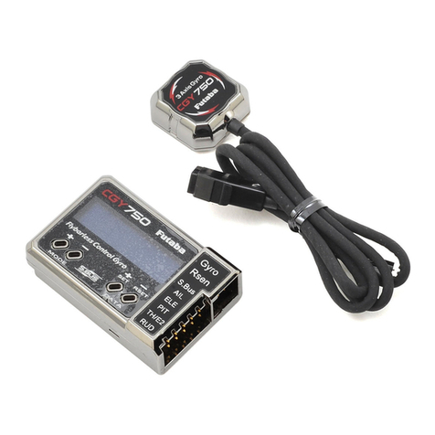
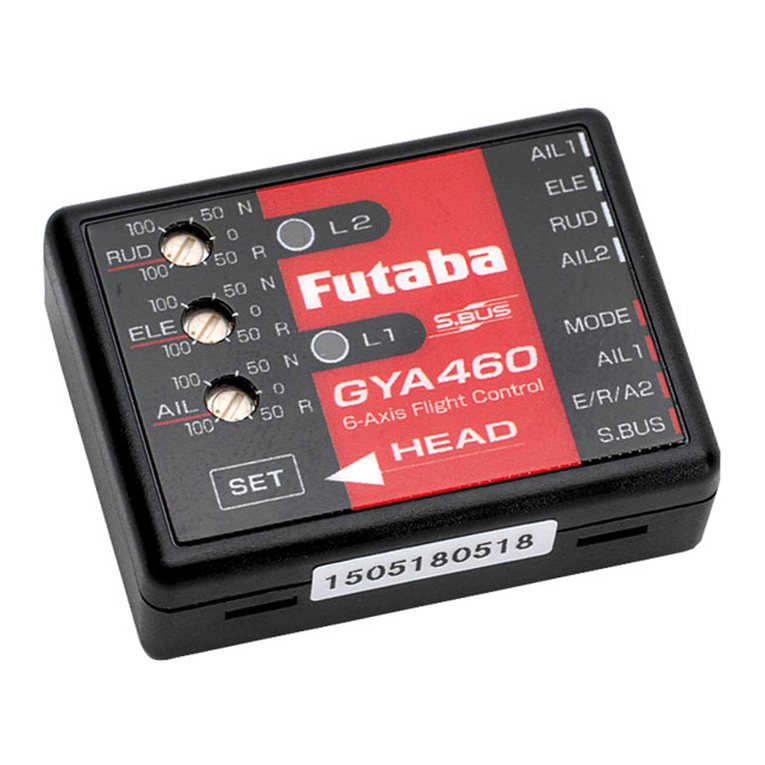
FUTABA T32MZ User manual

GyroSetting
T32MZVer3.3
Manual
1M23Z06809

TableofContents
TableofContents
◆ T32MZ-CGY755/CGY760RConnection
3
◆ WirelessTuningsFunctionList 3
◆ WiredConnectionSetting 4
◆ WirelessConnectionSetting 5
◆ HomeScreen 6
◆ BasicMenuMap 8
◆ S.BUSBasicMenu 9
◆ SwashBasicMenu 10
◆ FlightTune(Aileron/ElevatorBasicSettings)14
◆ RUDBasic(RudderGYROBasicSetting)17
◆ GOVBasic(GovernorBasicSetting)19
◆ ExpertMenuMap 21
◆ RUDExpert(RudderGyroExpertSetting)22
◆ FLT.Expert(Aileron/ElevatorGyroExpertSetting)25
◆ SwashDetail(SwashDetailSetting)26
◆ GOVExpert(GovernorExpertSetting)29
The descriptions and screens in this manual are subject to change with version upgrades.
With this update, the T32MZ has the same functions as the GPB-1.
The CGY755 / CGY760R can be set up from the T32MZ screen by connecting
to the T32MZ. Some functions can be set wirelessly.
CGY760R needs to be Ver3.0 ~. Update CGY760R.

3
B.Wirelesstunings:Gyrotuningscanbemadewirelessly.(Limiteditems)
T32MZ
CGY755/CGY760R
ForCGY755
(ForCGY760RUseotherreceiver)
S.BUS2Receiver
WirelessTuningsfunctionlist
Donotsetduringflight.Makesettingswhen
theaircraftisonthegroundandthemotor
andenginearestopped.
-FLT. TUNE
Base Gain: Gyro base gain setting
CYC. Rt: Cyclic rate setting
Cnt. AuthAIL: Control Authority Aileron
Cnt. AuthELE: Control Authority Elevator
EXPO.: Exponential
FLT. Styl: Flight style
ELE. Comp: Elevator pre compensation
-SWH. BASIC
SWS. Rate: Rate adjustment
PIT. Rate: Rate adjustment
SWS. Ring
- GOV. BASIC
GOV Gain: Governor gain
L Lmt. L rpm : Low limit hovering RPM
L Lmt. H rpm : Low limit idling RPM
-FLT. EXPERT
HeadHld A : Head hold aileron
StopTune A : Stop tune aileron
HeadResp: Head Response
HeadHld E: Head hold elevator
StopTune E : Stop tune elevator
-RUD. EXPERT
EXP. AVCS: Rudder exponential AVCS
EXP. NORM: Rudder exponential NORMAL
CNT. DlIn: Control delay in
CNT. DlOut: Control delay out
ANG: Pirouette speed
Tail Resp: Tail response
A.Wiredconnection:Advancedsettings(allfunctionssameasGPB-1)
T32MZ
S.I/F P.BOX
CGYConnectionCable(includedwithgyro)
CGY755/CGY760R
● Connectthereceiverbattery(3.5to8.4
V)to
oneofthe"AIL"to"S.B2"connectorsother
than"RPM"and"P.BOX".
(Donotconnectto"RPM"and"P.BOX".)
Notes
IftheT32MZandgyroarenotconnected,the
gyrosettingvaluecannotbechanged.
Notes
Whenusingthewirelesstuningfunction,set
thetelemetryfunctiontoACT.
ThewirelesstuningcanbeFASSTestorT-FHSS.

4
A.Wiredconnection:Advancedsettings
1.Select"Gyrosetting"onthelastpageof
HelicopterModelMenu
3.Homescreenisdisplayed
Tobasicmenu
Toexpertmenu
Toreceiver
2.Select"Start"
*Atthistime,ifGyroisnotconnectedtoT32MZbywire,theEQ
IDscreenappears.
1
3
2
SETTING
CAUTION
Be sure to connect and disconnect the CGY760R/CGY755 and
T32MZ connection cable with the power off.
◆ WhencopyingdatafromGyroAtoGyroB
ConnectthegyroAtotheT32MZandpress[Start].(EnterthedataofAintoT32MZ)
ConnectGyroBtoT32MZandpress[GYSettingsTransfer].(PutdataonAintogyroB)
Select"Start"Thiswilldownload
thegyrodatatotheT32MZ.
When"GYSettingsTransfer"is
selected,thegyrosettingdatasaved
inT32MZiswrittentothegyro.
IfyoupressStarthere,theBdatawillbewritten
totheT32MZandtheAdatawillbelost.

5
B.Wirelesstunings
ToconfiguretheWirelesstunings,settwoconsecutive
freechannelstouseforWirelesstuningsinSBUSBasic
4/4. Linkagemenu→Function
Exampleusing13CHand14CH
1.Select“Gyrosetting”onthelastpageof
HelicopterModelMenu
BeforemakingWirelesstunings,itisnecessarytodownloadthesettingdatafromthegyrototheT32MZviaawired
connection.
OncethegyrodataisstoredintheT32MZ,ifitisthesamegyro,thereisnoneedtomakeawiredconnectionfromthe
secondtimeon.Ifyouwanttouseanothergyro,youneedtoreconnectthecableanddownloadthedata.
First,wiredconnection
Next,Wirelesstunings
2.Select"Start"
ThiswilldownloadthegyrodatatotheT32MZ.
12
SETTING
T32MZ
S.I/F P.BOX
CGY755/CGY760R
1
3.Select"WirelessTuning"
3
2
4.Itemsthatcanbesetwirelesslyaredisplayed
4
1.Select“Gyrosetting”onthelastpageof
HelicopterModelMenu
2.Select"Start"
CGYConnectionCable(includedwithgyro)
● Connectthereceiverbattery(3.5to8.4
V)to
oneofthe"AIL"to"S.B2"connectorsother
than"RPM"and"P.BOX".
(Donotconnectto"RPM"and"P.BOX".)
2consecutivefreechannels SetoperationandtrimtoNULL.
Checkthatthegyrotobe
setmatchestheEQID.
When"GYSettingsTransfer"is
selected,thegyrosettingdatasaved
inT32MZiswrittentothegyro.

6
HomeScreen
HomeScreen
●SWS.Rate
●PIT.Rate
●SWS.Ring
●FLT.Styl
●Cnt.AuthAI
●Cnt.AuthEL
●EXPO
●HeadHld A
●HeadHld E
●StpTune A
●StpTune E
●HeadResp
●BaseGain AI EL
●CYC.Rt
●GOV.Gain
●L Lmt.H rpm
●L Lmt.L rpm
●BaseGain AI EL
●CYC.Rt
●GOV.Gain
●L Lmt.H rpm
●L Lmt.L rpm
Cond1 (Condition 1)
Switch DG1
●SWS.Rate
●PIT.Rate
●SWS.Ring
●FLT.Styl
●Cnt.AuthAI
●Cnt.AuthEL
●EXPO
●HeadHld A
●HeadHld E
●StpTune A
●StpTune E
●HeadResp
Cond2 (Condition2)
Neutral
Switch Channel Rate
WideNarrow
-100% 100%-35% 35%0%
*Indicates when the setup style is "3D".
Cond1 Cond2
Switch Channel Rate
Neutral
Cond1 Cond3 Cond5Cond4Cond2
-100% 100%-25%-75% 75%25%0%
-100%
100%
0%
Swash plate type
Displays the swash plate type set in
"SWH. BASIC" menu.
Home Screen Display
On the home screen, basic information such as swash type,
gyro operation mode, sensitivity and governor ON / OFF,
engine operating time etc, are displayed.
Forfunctionsthatcansetconditionsin
thismanual,mark Cond iswritten.
Condition number
With switch operation from the transmitter, several parameters can be switched by
setting up to 5 types of data. If you set the condition switch to the channel having
the AFR function of the transmitter and set the point for each flight condition with the
AFR point curve, it can also be linked with the flight condition switch.
•WheneithertheDG1orDG2switchisselected,thefollowingoptionsareavailable.
FunctionMenuofyourtransmitter(DG1).AssigningDG1toaswitchorflightmodeallowsthe
useoftwoseparatevaluesfortheconditionselectableparameters.
•Ifyousetaconditionswitchchannel,usingtheAFRfunctiononthatchannelsetaflatpoint
curveforeachflightcondition.Thenyoucanutilizeall5flightsconditions.
Set the point curve with AFR for each flight condition of the transmitter.
Governor ON / OFF
Indicates the ON / OFF switch status of the
governor function. When "ON" is displayed, the
governor function is activated.
Gyro operation mode /
Gyro gain
Displays "AVCS" or "Normal" operation
mode and gyro gain of aileron (roll),
elevator (pitch) and rudder (yaw) axis.
Roll and Elevator rate maximum display
This screen displays the maximum roll rate and maximum eleva-
tor rate recorded during flight. Data is reset when the power is
turned off. If you want to check the maximum rate, leave the pow-
er on after flight. Press and hold rate button to reset the display.
Battery voltage
Displays the voltage of the
receiver battery connected
to CGY.
RPM display
The maximum RPM of the engine or rotor head RPM mem-
orized by the governor during operation is displayed. Data
is reset when the power is turned off. If you want to check
multiple times during the flight, leave the power on after
flight. Press and hold RPM button to reset the display. Engine running time
Displays the running time of the engine. Up to 9,999
hours are displayed.
Press and hold time button to reset the display. The
operation time is stored in memory even when the
power is turned off until it is reset.

7
HomeScreen
Expertmenuscreen
Receiverscreen
Basicmenuscreen
◆ FlightTune(Aileron,Elevator)
◆SwashBasic(Swash)
◆RudBasic(Rudder)
◆GovBasic(Governor)
◆S.BUSBasic
◆ SwashDetail(Swash)
◆FLTExpert(Aileron)
◆RUDExpert(Rudder)
◆GOVExpert(Governor)
◆ InternalRx
◆RFtype
HomeScreen
HomeScreen

8
BasicMenu
BasicMenu
As the name suggests, this menu allows changes to the basic settings of CGY.
Make sure to set each "BASIC MENU".
Basicmenuscreen
◆ FlightTune(Aileron,Elevator)
◆SwashBasic(Swash)
◆RudBasic(Rudder)
◆GovBasic(Governor)
◆S.BUSBasic

9
S.BUSBasicMenu
S.BUSBasicMenu
The channel of each function
can be changed.
This resets the S.BUS channel assign-
ments back to the defaults.
The "SBUS BASIC"screen is accessed via the "BASIC MENU"screen. Set the CH for each function according to the transmitter to be used.
Any unused functions should be set to INH (Inhibited). For example, if the Gain A/E and Gain RUD remote gain functions are not going to
be used, then set them to [INH]. The CGY760R/CGY755 will then allow you to make gain adjustments within the respective menu.
WARNING
Always verify that the S.BUS function as-
signments match your transmitter’s function
(in the FUNCTION menu) assignments. If any
changes are made within the transmitter func-
tion assignments, then it will also be neces-
sary to make the changes within the S.BUS
function assignments. To change the channel,
CGY and T32MZ must be connected.
ELE2 channel Servo Type
(If you want to use the ELE2 port for purposes other than swash.)
This selects the ELE2 servo types. There are three types of the servo
driving frequency selection, AN:70
Hz, DG285
Hz, and 760
μS. All Futaba
digital servos can be operated with fastest DG:285
Hz mode but some
of other brands of servos do not support DG:285
Hz mode. In this case,
select the proper servo driving frequency per the manufacturer’s specifi-
cations.
If you select H4-00 or H4-45 with 4 servo swashes, cannot set this ELE2
port servo type. In that case, select all swash servo types in SWH basic
servo type.
Setting:AN:70
Hz/DG:760
μS/DG:285
Hz Initialsetting:DG:285
Hz
WARNING
The servo type parameter within the CGY must match the type of
servo you are using. Incorrect setting may damage the CGY or the
servo. Incorrect setting may also result in a loss of control during
flight.
S. BUS connection: Condition on change channel
Using the methodology described previously, determine the "Cond CH #" and
set the condition change channel of the transmitter. In this example, DG1 is the
conditional change channel.
As with the flight condition function of the transmitter, it is possible to utilize
pre-determined settings, each activated by a switch or switches on the
transmitter. By setting the condition switch on the channel with the AFR
function of the transmitter and setting the point for each flight condition with
the AFR point curve, you can switch the condition of CGY760R/CGY755 in
conjunction with the flight condition switch of the transmitter.
Wireless channel
The wireless channel uses two consecutive channels. For example, if CH13
is set to "# 1", CH14 is automatically set to "# 2". Therefore, when using this
function, two consecutive free channels are required for the transmitter. It is not
possible to use a channel assign that is used for another function.
CAUTION
Be sure to check the operation for all conditions 1 to 5 before flying.
The setting of "wireless CH" is possible only when the transmitter
and the CGY are powered off and the CGY is turned on.
Be sure to connect and disconnect the CGY and T32MZ connection cable
with the power off.
2consecutivefreechannels

10
SwashBasic
SwashBasic
The green display is the current state.
AIL ----------N
ELE---------R
RUD --------N
AIL ----------R
ELE---------N
RUD --------N
AIL ----------N
ELE---------N
RUD --------R
AIL ----------R
ELE---------R
RUD --------N
AIL ----------N
ELE---------N
RUD --------N
AIL ----------R
ELE---------R
RUD --------N
AIL ----------N
ELE---------R
RUD --------R
AIL ----------R
ELE---------N
RUD --------R
AIL ----------R
ELE---------N
RUD --------R
AIL ----------N
ELE---------N
RUD --------N
AIL ----------R
ELE---------R
RUD --------N
AIL ----------N
ELE---------R
RUD --------R
Gyro Set Dir--- 1
Gyro Set Dir--- 4
Gyro Set Dir--- 5
Gyro Set Dir--- 6
Gyro Set Dir--- 2
Gyro Set Dir--- 3
AIL ----------R
ELE---------R
RUD --------R
AIL ----------R
ELE---------R
RUD --------R
AIL ----------N
ELE---------N
RUD --------N
AIL ----------N
ELE---------N
RUD --------R
AIL ----------R
ELE---------N
RUD --------N
AIL ----------N
ELE---------R
RUD --------N
AIL ----------R
ELE---------N
RUD --------R
AIL ----------N
ELE---------N
RUD --------R
AIL ----------N
ELE---------R
RUD --------R
AIL ----------R
ELE---------R
RUD --------R
*Depending on the type of mounting plate,
it is also possible to mount as shown in
the figure.
*Depending on the type of mounting plate,
it is also possible to mount as shown in
the figure. AIL ----------R
ELE---------N
RUD --------N
AIL ----------N
ELE---------R
RUD --------N
CGY755 has no antenna
This menu is utilized to perform the basic setup of swash motion.
"SWH. BASIC"screen from the "BASIC MENU"screen.
The CGY760R/CGY755 is compatible with the following six types
swash plate.
WARNING
Do not connect the servo to the gyros until you select the
servo type in the "SWH. BASIC"menu.
*If the servo type is incorrect, it is possible to damage the servos or CGY.
(1) Setup style
3D mode contains a proven set of parameters which are good for not
only 3D but also F3C flying. F3C Mode and L.SCALE (Large scale
model) Mode are for unique or special tuning types only.
*When the style is changed, setting of AIL/ELE/RUD is re-initialized and
defaults are changed.
L.SCALE:Initialparametermodecorrespondingtoalargemachinewitha
totallengthof2.5
mormore.
(2) Gyro Set Dir: Mounting direction
Set the roll axis, pitch axis, yaw axis according to the mounting direction
of CGY. When the LED on the Gx side finishes blinking, please turn the
power off and on again to confirm that it is working properly.
Setting:1~6Initialsetting:1
WARNING
Ifyoudonotturnthepowerbackonafterchanging"GyroSetDir",thegyro
willnotoperateproperly,thereisariskofcrashing.
(3) Servo Type
This selects the swash servo types. There are four types or modes of the servo driving
frequency selection, AN:70
Hz, DG:95
Hz, DG:140
Hz, DG285
Hz, and 760
μS. All Futaba
digital servos can be operated with fastest DG:285
Hz mode but some of other brands of
servos do not support DG:285
Hz mode. In this case, select the proper servo driving fre-
quency per the manufacturer’s specifications.
Setting:AN:70
Hz/DG:95
Hz/DG:140
Hz/DG:760
μS/DG:285
Hz
Initialsetting:DG:285
Hz
WARNING
The servo type parameter within the CGY must match the type of servo you are
using. Incorrect setting may damage the CGY or the servo. Incorrect setting may
also result in a loss of control during flight.

11
SwashBasic
SwashBasic
H-1
SwashType
ELE
PIT AIL
H3-120
ELE
PIT AIL
H3-140
ELE
PIT AIL
H3-90
ELE2
ELE
PIT AIL
H4-00
ELE2
FRONT
ELE
PIT
AIL
H4-45
ELE
PIT AIL
H-1
(4) SWASH Type: Swash change to plate type
Select the swash plate type. When you change the setting, other data is
initialized.
Setting:H-1
/
H3-120
/
H3-140
/
H3-90
/
H4-00
/
H4-45 Initialsetting:H3-120
WARNING
All of the swash plate parameters are reset when the swash plate
type is changed. Doing so eliminates any possible errors or mal-
functions within the system. After changing the swash plate type,
Please proceed through the entire setup process once again before
attempting to fly the model.
AIL --------------------Aileron servo
ELE----------------- Elevator servo
PIT---------Collective pitch servo
ELE2 ---- Second elevator servo
Your transmitter should be reset to the default settings and the swash plate
type selected with the transmitter should be set to "H-1" or single servo
mode. All CCPM mixing is set up and handled in the CGY, and the transmit-
ter functions should not be used. Before starting model set-up, be sure that
all dual rates, pitch curve, and endpoint values are set to 100/100.
(5) Servo Dir #: Servo direction #
Using different servo combinations will create the proper swash plate servo
movement in electronic CCPM models (eCCPM). In the H3-xx swash
mode, three of the swash servos directions are changed by pressing the
Servo Dir #. Choose the combination number which produces level swash
plate travel with a collective pitch input from the transmitter. There are 8
combination choices for the H3-xx swash mode. On H4-xx swash mode,
there are 16 combination choices. After selecting the combination number,
aileron, elevator, pitch, and 2nd elevator servo parameters are automati-
cally set.
Note: Occasionally the aileron or elevator function directions are reversed
even though collective pitch direction is correct. In this case, use the "SWS.
Dir parameter on the following screen (4/6) to fix this later.

12
SwashBasic
SwashBasic
(6)AIL, ELE, PIT. Ntr:
Servo neutral adjustment
Adjust the neutral position of the swash servo (aileron, elevator, pitch,
second elevator). The second elevator (ELE2) is displayed only when the
swash type is H4-xx.
Settingranges:+240~-240Initialvalue:0
(7) SWS. Dir: Swash direction setting
This selects the aileron, elevator and collective pitch direction. Reverse
the direction when the stick movement and swash movement are oppo-
site. Each time you press the +/- button, the polarity switches.
(8) SWS. Rate: Rate adjustment
The Swash Rate settings are used to set a known base cyclic throw for the
gyro to calculate the compensations and gain scale. This value does not
represent the total cyclic throw, but rather shows the gyro a known point for
the gyro to understand the helicopters geometry. It is important to note that
one setting applies to both roll and pitch axes; they are not individually ad-
justed.
(DUAL RATES MUST BE 100)
-Suggested amount of base cyclic pitch
*800 size – 10 degrees
*700 size – 9 degrees
*600 - 550 size – 8 degrees
*500 size – 7 degrees
*450 and below- 6 degrees
Settingranges:0~100%Initialvalue:50%
(9) PIT. Rate: Rate adjustment
The [PIT.Rate] is the amount of collective pitch travel allowed. A good
starting range for Sport, 3D and F3C is +/-10 to +/-12 degrees.
Settingranges:0~100Initialvalue:50%
(10) SWS. Ring
This parameter is used to set the total maximum of cyclic throw as well as
limit the swash travel to prevent binding of the swash plate servos when the
control stick is moved toward a corner (for example, full right and full aft cy-
clic).
Settingranges:50~100%Initialvalue:130%
(11)
AGy. Dir: Aileron (roll) Gyro direction
EGy. Dir: Elevator (pitch) Gyro direction
This parameter controls which direction the CGY (roll / pitch axis) will
compensate when the helicopter rolls (pitches). Pick the helicopter up
and roll the helicopter to the right. The CGY should compensate by add-
ing left cyclic to the swash plate. (Pick the helicopter up and rotate the
nose of the helicopter downward. The CGY should compensate by adding
aft cyclic to the swash plate.)
If the CGY compensates in the wrong direction, then it will be necessary
to reverse the compensation direction setting.
WARNING
Verify that the CGY compensates in the correct direction before
flight. If the compensation direction is incorrect the model will roll
or pitch uncontrollably even before it leaves the ground.
(13) STK. Dir ELE: Elevator operation
Load the direction of elevator into the gyro.
[Setting method] Touch the "Up" button to enter the setting mode.
"Sure?" Is displayed. Operate the elevator stick fully to the up. If you touch
the [Yes] button, the operation direction of elevator is memorized.
(12) STK. Dir AIL: Aileron operation
Load the direction of Aileron into the gyro.
[Setting method] Touch the "Right" button to enter the setting mode.
"Sure?" Is displayed. Operate the Aileron stick fully to the right. If you
touch the [Yes] button, the operation direction of Aileron is memorized.
Be sure to set this aileron motion direction and elevator motion direction
so that F/F mixing (Ele Comp and Rud. F/F menu) works effectively. Also,
please perform this operation after setting the direction of operation.
*The current condition number of CGY is displayed.
*The setting with "C#" display can be set for each condition.
1. Use the "C#" button to select the condition number.
2. Next, adjust value of the condition selected by the rate
button.
Forfunctionsthatcansetconditionsin
thismanual,mark Cond iswritten.
Cond
Cond
Cond
WARNING
Verify that the CGY compensates in the correct direction before
flight. If the compensation direction is incorrect the model will roll
or pitch uncontrollably even before it leaves the ground.

13
SwashBasic
SwashBasic
(14) Pit.High: Pitch high memorizing
This parameter saves the full positive collective pitch point into the CGY.
[Setting method] Touch the "Pit. High" rate button to enter the setting
mode. "Sure?" Is displayed. Operate the throttle stick fully to the high. If
you touch the [Yes] button. The full positive pitch signal will be saved to
the CGY.
(15) Pit. Zero: Pitch zero memorizing
This parameter saves the zero collective pitch point into the CGY.
[Setting method] Touch the "Pit. Zero" rate button to enter the setting
mode. "Sure?" Is displayed. Operate the throttle stick to 0 degree pitch. If
you touch the [Yes] button. The zero pitch signal will be saved to the CGY.
(16) Pit. Low: Pitch low memorizing
This parameter saves the full negative collective pitch point into the CGY.
[Setting method] Touch the "Pit. Low" rate button to enter the setting
mode. "Sure?" Is displayed. Operate the throttle stick fully to the low. If you
touch the [Yes] button. The full negative pitch signal will be saved to the
CGY.

14
FlightTune(Aileron/ElevatorBasicsettings)
Flight tune sets control of helicopter roll (aileron) and pitch (elevator) axis. "FLT.
TUNE" screen from the "BASIC MENU" screen.
(2) CYC. Rt: Cyclic rate setting
Cyclic rate sets the maximum Cyclic rate sets the maximum roll and flip
rate (d/s) as limited by the model’s ability to reach that set rate. Flip and
roll rates are set together with this single parameter.
Settingranges:10~500
d/sInitialvalue:300
d/s
Cond
(1) Base. Gain: Gyro base gain setting
This sets the Cyclic Gyro Base Gain. If the Rotor Head Gain (Rot HD Gn)
Channels are set to "INH" within the CGY "SBUS.BASIC" menu, then the
remote transmitter gain adjustment is not available. Thus the actual work-
ing gain for the cyclic gyros is set by using the "Base Gain" button within
this parameter.
Set to 100, a transmitter Gain value of 100% will display 100% on this pa-
rameter. If a pilot is in need of more gain, base gain can be increased to
allow the gain on the CGY to be higher than 100%.
Note: If using a 6
CH or less "Base Gain" is equivalent to the rotor head
gain and can be adjusted manually on the gyro instead of via the transmit-
ter.
Settingranges:0~150%Initialvalue:100%
Cond

15
FlightTune(Aileron/ElevatorBasicsettings)
(3) Cnt. AuthAIL: Control Authority Aileron
Aileron Control Authority changes the rate at which the gyro will try to
achieve the set "CYC. Rt". A higher value will create a quicker accelerated
reaction to a stick input to reach and stabilize to the "CYC. Rt" value; a
lower value will reach the desired "CYC. Rt" slower and accelerate slower
to the desired angular rate.
Note: Setting this value too high could lead to a jerky feeling when mak-
ing rapid stick corrections, a value too low will give you the impression the
model is not following the pilot’s stick inputs. Values of between 20-60 are
the suggested range for most helicopters.
Settingranges:0~100%
Initialvalue:Cnt.AuthAIL=40%
(4) Cnt. AuthELE: Control Authority Elevator
Elevator Control Authority changes the rate at which the gyro will try to
achieve the set "CYC. Rt". A higher value will create a quicker accelerated
reaction to a stick input to reach and stabilize at the "CYC. Rt" value; a
lower value will reach the desired "CYC. Rt" slower and accelerate slower
to the desired angular rate.
Note: Setting this value too high could lead to a jerky feeling when mak-
ing rapid stick corrections, a value too low will give you the impression the
model is not following the pilot’s stick inputs. Values of between 20-60 are
the suggested range for most helicopters.
Settingranges:0~100%
Initialvalue:Cnt.AuthELE=40%
(5) EXPO.: Exponential
Tune the exponential as desired to change the feel of the cyclic controls
around center stick. Negative values soften control feel; Positive values
increase sensitivity.
Note: that any exponential present in the TRANSMITTER adds to the value
set in the CGY.
Settingranges:-100~0~+100%Initialvalue:-20%
(6) FLT. Styl: Flight style
Increasing this value will create a more robotic reaction to the stick, leaving
the pilot with the impression that the model is locked into in a position after
an input. It will also tend to have a more calculated feeling when making in-
puts.
-Lowering the value will make the model feel more fluid and easy to rotate with
the stick input. The model will feel a little more lively during faster cyclic move-
ments and direction changes.
Settingranges:0~+100
nInitialvalue:+50
n
Cond
Cond
Cond
Cond

16
FlightTune(Aileron/ElevatorBasicsettings)
Note:To effectively operate the next "ELE Comp"
(elevator correction), make sure to set "Pit High", "Pit
Zero", "Pit Low" on the "SWITCH BASIC" menu.
(7) ELE. Comp: Elevator pre compensation
A helicopter that has a head that rotates clockwise, will exhibit a tendency
whereby the nose will be pulled towards the disk with positive blade pitch.
Conversely, the helicopter will push the nose away from the rotor disk dur-
ing negative pitch inputs. In an instance of a slower servo set-up or larger
(heavier) rotor blades, a small amount of elevator pre compensation may
be needed to keep the nose of the helicopter flat at all times during col-
lective pitch changes. In most cases with helicopter high-speed servos
and standard 3D rotor blades, this function is not needed. If you do notice
a slight tendency for the nose to try to rise or fall with collective input, in-
creasing "ELE Comp" will reduce this behavior.
Settingranges:0~100%Initialvalue:0%
(8) HP. Auth.: High pitch authority
When a rotor blades angle of attack is increased, the rotor blade becomes
less reactive, in turn the helicopter might not feel as reactive at high pitch
angles. If you want to increase the reaction of the cyclic during loaded and
high pitch maneuvers, "HP. Auth" will increase control authority and can be
used to make the helicopter feel more linear under loading. Some helicop-
ters with direct link CCPM may use this to increase stability at high collec-
tive pitch flying as well. If a helicopter feels good for normal flying, but not
the same during loaded situations, "HP. Auth" can be used to make it feel
more linear. If "HP. Auth" is set very high, the helicopter will feel more ag-
gressive at high pitch than around neutral.
Settingranges:0~100%Initialvalue:HP.Auth=0%
Cond

17
RUDBasic(RudderGYROBasicSetting)
In the "RUD. BASIC"menu, you make the basic setting of the rudder gyro.
"RUD. BASIC"screen from the "BASIC MENU"screen.
WARNING
Do not connect the tail rotor servo to the gyro until the
servo type has been selected. Operating the servo using the
incorrect setting may damage the CGY or the servo.
Do not operate with the linkage connected until the "Srv.
Limit" function correctly sets the servo limit point. If the
servo operates beyond the linkage operating range, there is a
danger of either the servo or helicopter being damaged.
WARNING
The servo type parameter within the CGY must
match the type of servo you are using. Incorrect
settings may damage the CGY or the servo. An in-
correct setting may also result in a loss of control
during flight.
(1) Servo Type
Select the appropriate setting for the tail rotor servo.
Setting:Analog/DG:1520/DG760
Initialsetting:DG:1520
DG1520:BLS254,BLS257,S9254,S9257
DG760:BLS276SV,BLS251SB,BLS251,S9256,S9251
(2) Gyro. Dir: Gyro direction
This parameter controls which direction the CGY (yaw axis) will compen-
sate when the helicopter rotates. Hold the tail rotor linkage over the link-
age ball on the servo, pick the helicopter up by the main shaft and rotate
the mechanics counter-clockwise. The CGY should compensate by adding
clockwise rotation pitch to the tail rotor blades. If the CGY compensates by
adding counter-clockwise rotation pitch to the tail rotor blades, then it will
be necessary to reverse the Compensation Direction setting by pressing
the "Gyro Dir".
Settingvalue:Normal/ReverseInitialvalue:Normal
(3) Work Mode: Gyro working mode
The available choices are CMT, Normal or AVCS. The CMT mode will allow
you to select either AVCS or Normal mode via the transmitter. In Normal
mode the gyro will always operate in Normal Rate Mode, and when AVCS
is selected, it will always operate in AVCS Mode.
Setting:CMT/Normal/AVCSInitialsetting:CMT
(4) GY. Gain: Gyro base gain setting
This parameter sets the base gain of the gyro. This can be used to adjust
the gain % if your actual transmitter gain does not match the gain on the
CGY correctly.
Settingranges:0~150%Initialvalue:100%
(5) Srv. Limit: Limit setting
When the CGY is in the "Srv.Limit" parameter mode, the gyro will no lon-
ger operate and the tail servo will always center when the tail rotor stick
is released. Always exit the setup functions before attempting to fly the
model. Before each flight, always ensure that the gyros are operating and
compensating in the correct direction. The Servo Limit parameter within
the CGY is used to set the mechanical limits for the tail rotor servo. To
obtain the best performance it is recommended to set the limit in the CGY
to 100% for both directions and then adjust the servo arm length to set the
mechanical endpoints. After that has been completed, use the servo limit
parameter to make small adjustments that could not be made mechani-
cally. Values between 90% and 110% are considered optimal.
[ Setting method ]
Operate the rudder stick right or left in the direction you want to set. Touch
the button that is lit in green to set the limit. Do the same for the other side.
WARNING
When using the CGY for the first time, or when making mechani-
cal changes involving throw, you must check and set the servo limits
again to prevent binding.

18
GOVBasic(GovernorBasicSetting)
This menu sets the governor’s fundamental functions. The menu Servo limit point set-
WLQJPXVWEHVHW¿UVW
"GOV. BASIC"screen from the "BASIC MENU"screen.
Note: When using the governor function, be sure
to make each setting of "GOV.BASIC".
Note: After completing the linkage of the throttle,
be sure to set the "Servo limit point setting" first,
and then set the other functions.
(1) Governor: Governor active
Set the governor operation mode of CGY. The initial setting is "ACT (active)"
where, as the designation implies, the governor is active. If you do not want
to use governor, select "INH (Inhibit)".
Setting:ACT(Active)/INH(Inhibit)Initialsetting:ACT
(2) Gear Ratio:
Input the main rotor gear ratio by pushing the "Gear Ratio" button to select
the desired working mode.
Settingranges:1.00~50.00
tInitialvalue:8.00
t
Notes:
• If the gear ratio is not properly set, the
set speed and actual engine speed will
be different.
•The gear ratio should be given in the
helicopter instruction manual. If the
helicopter instruction manual does not
give the gear ratio, calculate the gear
ratio as follows:
Rotor
main gear
N1
Engine
nion gear
N2
Gear ratio = N1/N2
Carry values less than 1/1000 to the
next whole number.
(3) Pole Num.: Pole number
This parameter is used when using a direct phase sensor attachment to a
brushless motor lead. Input the motor pole count as specified by the brush-
less motor manufacturer. When using any revolution sensor other than a
direct phase sensor type, set the pole number to 2
p.
Note: For nitro use, set to 2
p.
Note: The input signal range of the CGY is 0.0
v - 3.0
v. Exceeding this volt-
age range may cause damage to the CGY.
Settingranges:2-24
PInitialvalue:2
P
(4) Servo Type
Select the throttle servo type. Digital servos offer the best response.
Setting:Analog/DG:1520Initialsetting:Analog
WARNING
The servo type parameter within the CGY must match the type of
servo you are using. Incorrect settings may damage the CGY or the
servo. An incorrect setting may also result in the loss of control during
flight.
(5) RPM set.: RPM setting
Setting the main rotor RPM. This is calculated by engine revolution with
the gear ratio of the main shaft.
When the rotation speed can be set with the governor mixing function of
the transmitter, it is necessary to first match the display rpm value of 1-2-3
of "RPM Set" with the display rpm value of the transmitter.
Settingranges:off/700~4,000
rpmInitialvalue:1,000
rpm
*Tosetlowerthan1,000
rpm,set"Low.Revo"of"GOV.EXPERT"menuto700
rpm.

19
GOVBasic(GovernorBasicSetting)
(6) Stick sw.: Stick switch
The governor can be activated by throttle stick position.
[Setting method] Touch the "Stick SW" button to enter the setting mode.
"Sure?" Is displayed. Operate the throttle stick to the position where you
want to turn Governor ON. If you touch the [Yes] button, the ON position is
memorized. This stick switch function is always enabled when the next "ON
/OFF sw" is "INH" or the "Governor ON / OFF switch is not set by S.BUS set-
ting.
Whengovernoristurnedonandoffbytransmitterthrottlestick
The data is set so that the governor can be
turned on and off with the transmitter throttle
stick position. The following describes this op-
eration.
• Throttle stick over set point and more than 60%
of set rotation speed. ON
*This is the setting value of "Gov. On. Revo: Gov-
ernor ON revolution setting".
• Throttle stick held at the set point or more Re-
mains. ON
• Throttle stick position is below the set point se-
lected. OFF
When idle up
• When the throttle curve is set at idle up, and when the throttle output is over the set
value (initial value: 30%), the governor will always and remain ON even if the stick is
lowered to the bottom.
(OFF at slow side)
Set point or less
0%
100%
(Governor operating point)
Set speed
The stick is at, or be-
yond the set point and
is 60% of the rotation
speed value of the gov-
ernor.
When you activate the switch, the direction setting of the switch is displayed.
Select the switch ON /OFF direction (Normal /Reverse).
Whenturningon/offgovernorwithswitch
Select the ON / OFF switch channel with "GOV sw channel" on "SBUS BASIC"
menu.
Setting the switch to the ON position turns on, or enables the
governor. The following describes this operation.
• Switch set to on position and engine running at 60% or more
of set speed ON
• Throttle stick set to maximum slow position ON
• Switch set to off position OFF
(7) ON/OFF sw.: Governor on/off switch
This parameter allows the user to turn the governor on or off via a switch
on the transmitter. Choose INH if you do not want to use it.
Governor can be turned
on and off by a switch.
When Battery Fail Safe is enabled, items for setting the throttle servo posi-
tion are displayed. The setting method is the same as "Stick sw", so please
refer to this section of the manual for information on setting this function.
(8) BAT F/S: Battery fail safe
When the receiver battery voltage becomes equal to or less than "BFS.
Volt" set in the "GOV EXPERT" menu, the battery fail safe function is acti-
vated, the governor function is turned OFF, and the throttle servo moves to
the set position.
If the battery voltage is lower than the set voltage of the "Battery F/
S"for about 3 seconds, the Gx (gyro) LED of the CGY solid red light.
When "Battery F/S"is set to "ACT"in "GOV BASIC", the servo is fixed
to the throttle position set by "Battery F/S". When the throttle stick is
set to the slowest position, the "Battery F/S"function is temporarily
canceled. However, after 30 seconds, the "Battery F/S"function is
activated again and the servo is locked. When the "Battery F/S"oper-
ates, quickly landing and stopping the helicopter, please charge the
battery.
WARNING
When using the CGY for the first time, or when making changes in
the throw of a servo and its linkage, always perform the limit setting
operation.
WARNING
When using the CGY for the first time, or when making changes in
the throw of a servo and its linkage, always perform the limit setting
operation.
(9) Lim. set: Servo limit point setting
Servo limit point setting defines the overall travel range for the throttle ser-
vo. It is fundamental for governor operation and must be set prior to other
functions. Servo limits must also be reset when the throttle linkage or trim
are changed.
How to set the servo limit point:
Set the transmitter's throttle stick to the idle position. Select [Lim. Set Id].
"Sure?" Is displayed. If you touch the [Yes] button.
The limit of idle will be
saved to the CGY.
The cursor will move to "Lim. Set Hi". Set the stick to the
full high position and set the same as "Lim. Set Id". If the setting data is not
normal (servo operation amount is 50% or less), "Err" is displayed. In this
case, check the transmitter setting and repeat this procedure once again.
(10) Limit Test: Check the set limit point
Check the set limit point. Press "Idle" or "High" to move the servo to each
limit point. Press “End” to end the test.

20
GOVBasic(GovernorBasicSetting)
(11) SenseTyp: Sensor type
Select the type of governor sensor.
Nitro (BPS-1 backplate; Magnet Type)
1:1 Magnet "1:1 Magn" (Magnet type applied to helicopter part that turns at
the same RPM as the main rotor)
HPoleEP: For Electric motors 8 poles and above
LPoleEP: For electric motors 6 poles.
(12) GOV Gain: Governor gain
Governor Gain. If the value of the Governor Gain is set too low, the heli-
copter's RPM will fluctuate with collective and cyclic pitch changes. Con-
versely, if the number is too high, the RPM itself will fluctuate and surge
during flight.
Settingranges:1~100%
Initialvalue:Nitro=40%,1:1Magn=60%,HPoleEP=30%,LPoleEP=10%
Cond
(13) L Lmt. L rpm / H rpm: Low limit RPM
Low RPM Limit sets the minimum amount of throttle that the governor will
command during an over-speed situation. Too low of value the engine
could shut off or not recover power quickly enough during the next collec-
tive movement. If the value is set too high, the governor will not control
overspeed when the rotor head is unloaded.
Use:
L Lmt. L rpm: For RPMS of 700-1700
L Lmt. H rpm For RPMS of 1701-4000
Settingranges:LLmt.L
rpm=0~80%,LLmt.H
rpm=10~80%
Initialvalue:LLmt.L
rpm=25%,LLmt.H
rpm=45%
Cond
(14) SBUS2 rpm out: RPM display on transmitter
When displaying the rpm with the telemetry function, set it to ACT.
Setting:ACT(Active)/INH(Inhibit)Initialsetting:INH
(15) SBUS2 rpm Slot: RPM display on transmitter
Set the slot number of the telemetry rotation sensor registered on the
transmitter side.
Thismustbesetsothatnoslotsoverlaponeanother.
(16) Rev. Sensor: Revolution sensor testing
This menu is utilized to ensure that the revolution sensor is functioning properly.
In order to test the sensor, do NOT start the engine. Instead, we recommend turning the engine over by hand or the utilization of a starter. To prevent inadvertent
ignition of the engine, do NOT use a glow plug igniter when turning the engine over.
The numerical values on the left side of the display are the current value. The right side of the display indicates the maximum sensor value. The output level needs
to be more than 60% for correct governor operation. Also, when using the backplate sensor, the signal level of the backplate sensor varies depending on the rota-
tion speed (3,000
rpm or more is the detectable rotation speed).
By the telemetry function, the number of revolutions read by the governor sensor can be displayed on the monitor of the transmitter. In order to be able to display, activate the telemetry ro-
tation sensor (SBS-01RM) on the transmitter and set the gear ratio to 1.00.
Note: It can not be used when the transmitter is FASSTest 12
CH system.
Other manuals for T32MZ
3
This manual suits for next models
2
Table of contents
Other FUTABA Control System manuals
Popular Control System manuals by other brands

Warner Electric
Warner Electric CBC-500 Series installation instructions

HWH
HWH 725 SERIES Operator's manual

Danish Interpretation Systems
Danish Interpretation Systems CCS 7800 installation manual

Compool
Compool Pool-Spa Control System Time Master installation instructions

Fagor
Fagor 8070 BL Programming manual

TMP
TMP Evo Chev installation guide