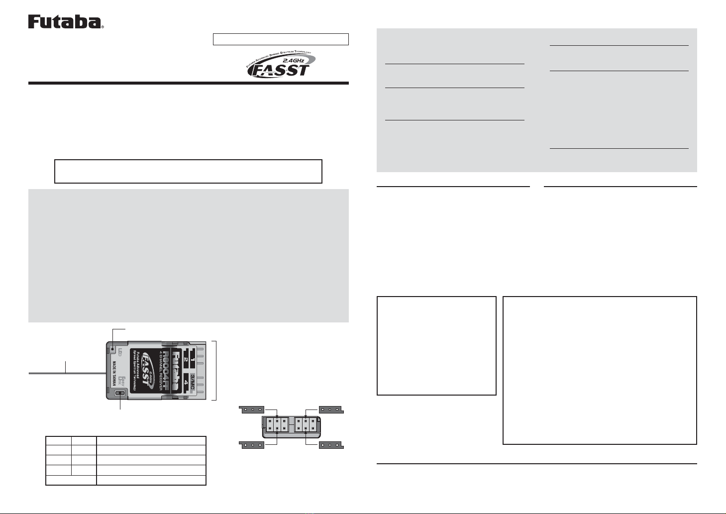
4: CH4 2: CH2
3/MC: CH3/ESC 1: CH1
FUTABA CORPORATION Phone: +81 475 32 6982, Facsimile: +81 475 32 6983
1080 Yabutsuka, Chosei-mura, Chosei-gun, Chiba-ken, 299-4395, Japan
1M23N17426 ©FUTABA CORPORATION 2010, 8 (1)
For Indoor Use Aircrafts
R6004FF
Thank you for purchasing the R6004FF FASST 4(four)
channel receiver. This model is designed for short range
application such as indoor use aircrafts.
The R6004FF is compatible with the FASST transmitters as shown below.
T6EX, T7C, T8FG(on 7ch mode), T10CG(on 7ch mode),
TM7, TM8(on 7ch mode), TM10(on 7ch mode), TM14(on 7ch mode)
Connectors
1: CH1 servo
2: CH2 servo
3/MC: CH3 servo/ESC connector
4: CH4 servo
Easy Link Button
Antenna
LED
Compliance Information State-
ment (for U.S.A.)
This device, trade name Futaba Corporation of America,
model number R6004FF, complies with part15 of the
FCC Rules. Operation is subject to the following two
conditions:
(1) This device may not cause harmful interference, and
(2) This device must accept any interference received,
including interference that may cause undesiredoperation.
The responsible party of this device compliance is:
Futaba Service Center
3002 N Apollo Drive Suite 1, Champaign, IL 61822 U.S.A.
R6004FF Specifica-
tions
•
Power requirement: 4.0V-8.5V
• F/S and Battery F/S function
(for channel three)
• Battery F/S voltage: 3.8V
• Size: 20.5x35.3x7.5mm
(0.81x1.39x0.30in.)
• Weight: 3.8g (0.13oz.)
nWARNING
Antenna Precautions
lDo not fold or cut the receiver an-
tenna as it cause shorter range.
lDo not apply any excessive force
to the antenna as it may damage
the wire.
jThe receiver antenna's location
must be away from metal objects
such as servo wiring, motor wiring, or
batteries at least half inch as it keeps
better receiving result.
Connector Precautions
lNever remove the case to avoid
the unexpected malfunction.
jThe connectors are covered with
the case but the material of the
case is relatively soft as it may cause
the reverse connection thus please pay
great attention when connect a battery
or an ESC to keep the correct polarity.
Otherwise the receiver may break down
or the wire may burn out.
jKeep away from conductive ma-
terial to avoid the short circuit.
Easy Link Switch
Press and hold,
1
One(1) second to re-set F/S
position for 3ch.(with TM7, TM8)
2
More than two(2) seconds to re-
link the transmitter's ID.
* Place the transmitter within 2 ft. (60cm)
to re-link.)
Range Check the Radio
1
Please follow the transmitter's
instruction manual and check if
the range is over 10 paces.
LED Indication
Green Red Status
Off Solid No signal reception
Solid Off Receiving signals
Blink Off Receiving signals but ID is unmatched
Alternate blink Unrecoverable failure (EEPROM, etc.)
Limited flight range: 300ft. max.
Usage Precautions
This model is designed for short range application such as indoor use aircrafts. Please
read the usage condition shown below.
s$ONOTEXCEEDFTMFORmIGHTRANGE
s4RANSMITTERgSANTENNAMUST./4POINTTOTHE RECEIVERWHENmYINGASSPECIlED INTHE
transmitter's instruction.
s0LEASEBESURE THAT THE %3#gS REGULATED OUTPUTFOR RECEIVERHAS ENOUGH CAPACITYTO
sustain the entire operating condition of your servos, battery, and motor.
s!FTERTHELINKINGISDONEPLEASECYCLERECEIVERPOWERANDCHECKIFTHERECEIVERTOBE
linked is really under the control by the transmitter to be linked.
s0LEASEDONOTPERFORMTHELINKINGPROCEDUREWITHMOTORgSMAINWIREISCONNECTEDASIT
may result in serious injury.


