WARNING
Do not perform the linking procedure while the motor's main wire con-
nected or the engine is operating as it may result in serious injury.
When the linking is complete, please cycle the receiver power and en-
sure the receiver is properly linked to the transmitter.
Please power up your system in this order. Transmitter first, followed
by the receiver.
FUTABA CORPORATION
<DEXWVXND&KRVHLPXUD&KRVHLJXQ&KLEDNHQ-DSDQ
3KRQH)DFVLPLOH
Link to the transmitter
(DV\/LQN,'DOORZV7)+66$LUUHFHLYHUVWROLQNWRFRPSDWLEOH
transmitter without pressing the link button on the receiver.
1Bring the transmitter and the receiver close to each other,
within 20 inches (half meter).
2 Turn on the transmitter. Place the transmitter into the receiver
linking mode.
3Turn on the receiver.
4The receiver will wait for the linking process to begin for 3
seconds. Following that it will return to the normal operation
mode.
5 When the LED of the receiver changes from blinking red to
solid green, linking is completed.
(A link waiting state is ended in 3 second.)
• Refer to the transmitters operation manual for complete details on how to place the
transmitter into the linking mode.
• If there are many T-FHSS Air systems turned on in close proximity, your receiver
might have difficulty establishing a link to your transmitter. This is a rare occurrence.
However, should another T-FHSS Air transmitter/receiver be linking at the same
time, your receiver could link to the wrong transmitter. This is very dangerous if you
do not notice this situation. In order to avoid the problem,we strongly recommend
you to double check whether your receiver is really under control by your
transmitter.
• If the System Type of the transmitter is changed, the receiver will need to be re-
linked to the transmitter.
Channel Modes (S.BUS ⇔6CH )
The R3006SB is capable of changing its channel allocations as described
in the table below.
1 Turn on the receiver. (At this moment, the transmitter should
be off.) Then, LED blinks RED in about 3 seconds. Next, wait
until it becomes solid RED.
2 Press and hold the Mode switch more than 5 seconds.
3Release the button when the LED blinks RED and GREEN
simultaneously.
4 The receiver is now in the "Operation CH Set" mode. At this
moment, the LED indicates current set status through flashing
a pattern that corresponds to the CH mode.
&DQQRWH[LWWKLV&+VHWWLQJPRGHEHIRUHWKHRSHUDWLRQPRGHLV¿[HG
6HHWKHEHORZWDEOHWKDWVKRZVFRUUHVSRQGHQFHEHWZHHQ&+PRGHDQGZD\
RIÀDVKLQJ/('
'HIDXOW&+PRGHLV0RGH&+
5By pressing the Mode switch, the operation CH is switched
sequentially as " Mode A" "Mode B" "Mode A"....
6The operation mode will be set by pressing the Mode switch
more than 2 seconds at the desired CH mode.
7Release the button when the LED blinks RED and GREEN
simultaneously. Then, the operation CH is fixed.
6After confirming the operation CH mode is changed, turn off
and back on the receiver power.
7KH³2SHUDWLRQ&+6HW´PRGHFDQQRWEHFKDQJHGGXULQJWKHUHFHLYHU
communicates to the transmitter.
T-FHSS Air
T-FHSS Air is a bidirectional communication system between the
56% UHFHLYHUDQG7)+66$LUFDSDEOHWUDQVPLWWHUV0XOWLSOH
optional telemetry sensors may be connected to the S.BUS2 on the
receiver and that data is in turn displayed on the transmitter.
*Please see your transmitters operation manual to configure transmitter to
operate with telemetry sensors.
S.BUS2
S.BUS2H[WHQGV S.BUS and supports bidirectional communication.
Sensors are connected the S.BUS2 port.
*Only S.BUS2 capable devices may be connected the S.BUS2 port.
Standard S.BUS servos and gyros should not be connected the S.BUS2
port.
If the R3006SB receiver was previously linked to another transmitter,
make sure that transmitter is not operating while linking the receiver to
the new transmitter.
ModeA ModeB
6/SB 6CH S.BUS
RedLEDblink 1time 2time
56%&+0RGHWDEOH
WARNING
Turn on the power in transmitter →receiver order. In addition, always check the operation of all the servos before flight.
Do not insert or remove the servo connector while the receiver power is ON.
Since the S.BUS servo switches the operation mode automatically according to the type of signal (S.BUS signal/PWM signal) from the receiver, if the connector is inserted
or removed while the power is ON, an S.BUS connected servo will be erroneously recognized and may stop.
©FUTABA CORPORATION 2015, 05 (1)
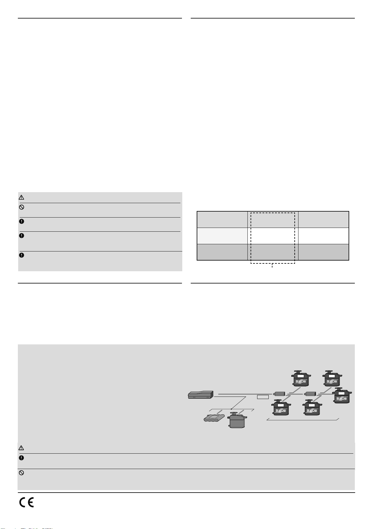
What is S.BUS?
Unlike conventional radio control systems, the S.BUS system uses data
communication to transmit control signals from a receiver to a servo,
gyro, or other S.BUS compatible device. This data includes commands
such as “move the channel 3 servo to 15 degrees, move the channel 5
VHUYRWR GHJUHHV´WRPXOWLSOHGHYLFHV7KHS.BUSGHYLFHV H[HFXWH
only those commands for their own set channel. For this reason, it can
be used by connecting multiple servos to the same signal line. S.BUShub S.BUShub
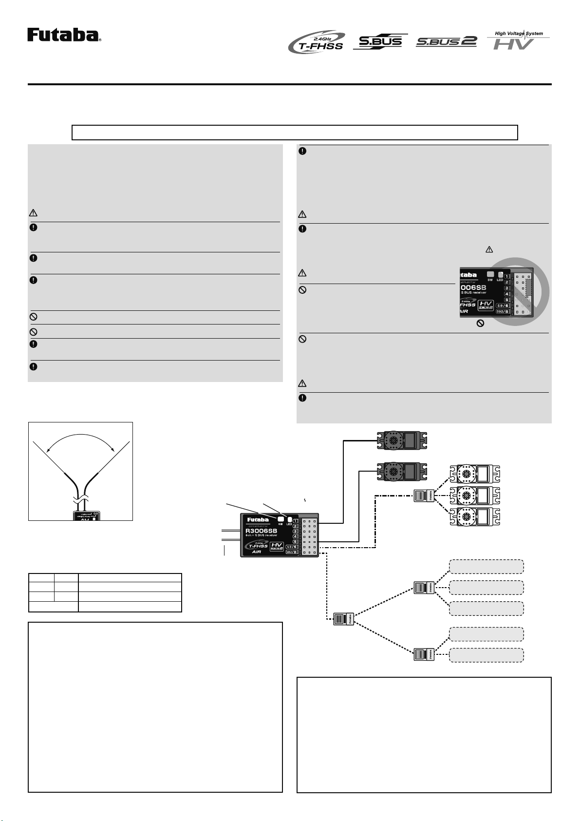
S.BUSoutput
S.BUS
Choutput/
Batteryterminal
R3008SB
Battery S.BUSservo
Conventional
servo
2ch 4ch
3ch 5ch
6ch
[Connection by S.BUS system]
* Set the channel of S.BUS servos by using an SBC-1 channel changer, CIU-2 USB
serial interface or the programming software resident in the T6K transmitter.
* Can also be used together with conventional servos. However, conventional ser-
vos cannot be used by the S.BUS output.
* When using servos with a remote battery pack, use S.BUS Hub with Cable (2-
way/remote battery pack use).
Please refer to the instruction manual of S.BUS Hub with Cable (2-way/remote
battery pack use) for the connection method.
'HIDXOW&+PRGH