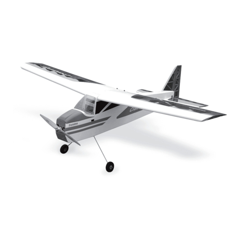
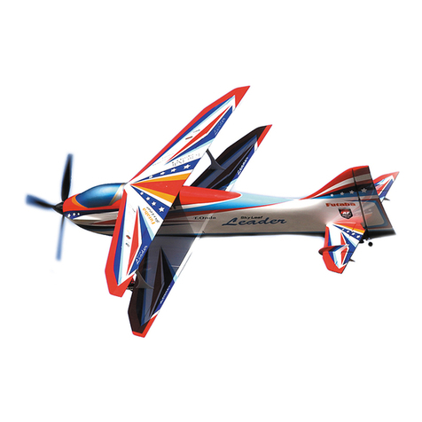
FUTABA Big SkyLeaf User manual

1M23Z06705
%,*3/$1( *6
5&PRGHO$HUREDWLF3ODQH
*3*DVROLQH(QJLQHFF

2
)XWDEDJXDUDQWHHVWKLVNLWWREHIUHHIURPGHIHFWVLQERWKPDWHULDODQG
ZRUNPDQVKLS DW GDWH RI SXUFKDVH 7KLVZDUUDQW\GRHVQRWFRYHUDQ\ FRPSRQHQW
SDUWVGDPDJHGE\XVHRUPRGLrFDWLRQ,QQRFDVHVKDOO)XWDEDOLDELOLW\H[FHHGWKH
RULJLQDOFRVW RIWKH SXUFKDVHGNLW )XUWKHU )XWDEDUHVHUYHVWKHULJKW WRFKDQJH RU
PRGLI\WKLVZDUUDQW\ZLWKRXWQRWLFH
,Q WKDW )XWDED KDV QR FRQWURO RYHU WKH ILQDO DVVHPEO\ RU PDWHULDO XVHG IRU ILQDO
DVVHPEO\QROLDELOLW\VKDOOEHDVVXPHGQRUDFFHSWHGIRUDQ\GDPDJHUHVXOWLQJIURP
WKH XVH E\ WKH XVHU RI WKH rQDO XVHUDVVHPEOHG SURGXFW %\ WKH DFW RI XVLQJ WKH
XVHUDVVHPEOHGSURGXFWWKH XVHU DFFHSWVDOO UHVXOWLQJOLDELOLW\ , I WKH EX\HU LV QR W
SUHSDUHGWRDFFHSWWKHOLDELOLW\DVVRFLDWHGZLWKWKHSURGXFWWKHEX\HULVDGYLVHGWR
UHWXUQWKLVNLWLPPHGLDWHO\LQQHZDQGXQXVHGFRQGLWLRQWRWKHSODFHRISXUFKDVH
Thank you for purchasing Futaba Sky Leaf R/C airplane.
To maximize your enjoyment, and to ensure proper
flying, please read through this assembly
instruction manual.
ŤƓƓƏƌƆƄƗƌƒƑŃƄƑƇŃƐƒƇƌƲƆƄƗƌƒƑŃƓƕƈƆƄƘƗƌƒƑƖő
1. This product is only designed for use with radio control models. Use of the product described in this instruction manual is
limited to radio control models.
2. Modification, adjustment, and parts replacement:
Futaba is not responsible for unauthorized modification, adjustment, or replacement of parts on this product.
3.Your Sky Leaf should not be considered a toy, but rather a sophisticated, working model that functions very much like a full-
size airplane. Because of its performance capabilities, this airplane, if not assembled and operated correctly, could possibly
cause injury to yourself or spectators and damage to property.
4.You must assemble the model according to the instructions. Do not alter or modify the model, as doing so may result in an
unsafe or unflyable model. In a few cases the instructions may differ slightly from the figures. In those instances the written
instructions should be considered as correct.
5.You must take time to build straight, true and strong.
6.You must use an R/C radio system that is in good condition, a correctly sized engine, and other components as specified in
this instruction manual. All components must be correctly installed so that the model operates correctly on the ground and
in the air.You must check the operation of the model and all components before every flight.
7. If you are not an experienced pilot or have not flown this type of model before, we recommend that you get the assistance
of an experienced pilot in your R/C club for your first flights. If you're not a member of a club, your local hobby shop has
information about clubs in your area whose membership includes experienced pilots.
8. While this kit has been flight tested to exceed normal use, if the plane will be used for extremely high stress flying, such
as racing, or if a engine larger then one in the recommended range is used, the modeler is responsible for taking steps to
reinforce the high stress points and/or substituting hardware more suitable for the increased stress.
■No part of this manual may be reproduced in any form without prior permission.
■The contents of this manual are subject to change without prior notice.
■Futaba is not responsible for the use of this product by the customer.
■Company and product names in this manual are trademarks or registered trademarks of the respective company.
Precautions

3
Forsafeuse
Please observe the following precautions to ensure safe use of this product at all times.
Meaning of Special Markings:
The parts of this manual indicated by the following marks require special attention from the standpoint of safety.
DANGER - Procedures which may lead to dangerous conditions and cause death/serious injury if not carried out
properly.
WARNING - Procedures which may lead to a dangerous condition or cause death or serious injury to the user if not
carried out properly, or procedures where the probability of superficial injury or physical damage is high.
CAUTION- Procedures where the possibility of serious injury to the user is small, but there is a danger of injury, or
physical damage, if not carried out properly.
= Prohibited = Mandatory
WARNING:AlwayskeepR/Ccomponentsawayfromsmallchildren.
Assembly precautions
We,asthemanufacturer,provideyouwithagood
quality,thoroughlytestedkitandinstructions,but
ultimatelythequalityandflyabilityofyourfinishedmodel
dependsonhowyoubuildit;therefore,wecannotin
anywayguaranteetheperformanceofyourcompleted
airplane,andnorepresentationsareexpressedorimplied
astotheperformanceorsafetyofyourcompleted
airplane.
Takeyourtimeandfollowtheinstructionstoendup
withawell-builtmodelthatisstraightandtrue.
First-timebuildersshouldseektheadviceof
experiencedmodellersbeforebeginningassemblyandif
theydonotfullyunderstandanypartoftheconstruction.
Installingamorepowerfulenginethanspecifiedor
flyingthehi-speedaggressivelymayleadtoserious
damageandaccidents.
Maketheassemblycorrectwiththismanual.
■Iftheassemblymanualisnotfollowed,inflightfailureordanger
tomodelandpropertycouldoccur.
DonotflybeforeconfirmingthecorrectlocationoftheC.G.
■ IftheCGisincorrect,themodelwillbedifficulttoflyandcould
leadtoacrash.
Sincethedirectionoftheservosofanairplanecanbe
easilymistaken,beverycareful.
■Doublecheckthatalldirectionsarecorrect.
Donotuseanoverpoweredmotor/engineortoolarge
ofpropelleronthisairframe.
■Whennotequippedproperly,theperformancemightnotbeas
describedbythemanufacturer.
Makesurethatallsurfacesarelevelbeforeflying.
■Ifthesurfacesarenotlevel,theairplanewillnotflystraightand
willbehardtocontrol.
Assemblethisairplaneonlyinplacesoutofchildren's
reach.
■Asmallchildmayaccidentallyoperatethesystem.Thiscould
causeadangeroussituationandinjuries.Eachpartcanbevery
dangerouswhenmishandledandcausechemicaldamage.
Usegluesandadhesivesthatareneededforassembly
inawellventilatedarea.
■Poorventilationcouldleadtotoxicfumesbeinginhaled.
DANGER
Donotdirectlyexposemodeltofuel,oil,exhaustgas,
etc.
■Ifleftinsuchanenvironment,themodelmaybeattackedand
damaged.
Donotaddanyextradevicesthatarenotsuggestedby
thefactoryontheairplane.
■Iftheairplaneischangedtoomuch,themanufacturecannot
promisecorrectperformance.
Storage and disposal precautions
Other precautions
CAUTION
Donotstoredevicesinthefollowingplaces:
・Whereitisextremelyhot(30℃[86F]orhigher)orcold(0℃[32F]
orlower)
・Wheretheequipmentwillbeexposedtodirectsunlight
・Wherethehumidityishigh
・Wherevibrationisprevalent
・Whereitisverydusty
・Wherethedevicemaybeexposedtosteamandheat
CAUTION
Whenthedevicewillnotbeusedforalongtime,
removethebatteryfromthetransmitterandaircraft
andstoretheminadryplacewherethetemperatureis
between0and30℃ [32Fand86F].
■Leavingbatteriesinsideyourmodelandradiowhentheyarenot
beingusedforlongperiods willresultinbatterydeterioration,
liquidleakageandotherdamage.
JointheAcademyofModelAeronautics.
■TheAcademyofModelAeronautics(AMA)providesguidelines
andliabilityprotectionshouldtheneedarise.
AlwaysusegenuineFutabaproductssuchas
transmitter,receiver,servo,etc.
■Futabaisnotresponsiblefordamagesustainedbycombination
withotherthanFutabaGenuineParts.Usethepartsspecifiedin
theinstructionmanualandcatalog.

4
Flying precautions
DANGER
Takeenoughsafetyprecautionspriortooperatingthis
model.Youareresponsibleforthismodel'sassemblyand
safeoperation.
First-timefliersshouldseekadviceforhintsinpre-
flightadjustmentsandassemblyfromexperiencedfliers.
Beremindedthatflyingabadlyassembledorbadly
adjustedairplaneisverydangerous.
Inthebeginning,first-timefliersshouldalwaysbe
assistedbyanexperiencedflierandneverflyalone.
Beforeflyingyourairplane,ensuretheairfieldis
spaciousenough.Alwaysflyitoutdoorsinsafeareaswith
nodebrisorobstacles.
Ensurethepropelleraresecurelyinstalled.
Donotflyyourairplaneondayswithstrongwindsor
sidewinds.
Donotallowabystandertogettooclosetothe
propeller.
Donotusedefectivepropellers.
Nevergraspthetransmitterantennawhileflying.
■Thetransmitteroutputmaydropdrastically.
Alwaysmakesurethatalltransmitterstickmovements
operateallservosproperlyinthemodelpriortoflight.
Also,makesurethatallswitches,etc.functionproperly
aswell.Ifthereareanydifficulties,donotusethesystem
untilallinputsarefunctioningproperly.
Whileoperating,nevertouchthetransmitterwith,
orbringthetransmitternear,anothertransmitter,acell
phone,orotherwirelessdevices.
■Doingsomaycauseerroneousoperation.
Donotpointtheantennadirectlytowardtheaircraft
duringflight.
■Theantennaisdirectionalandthetransmitteroutputisweakest.
(Thestrengthoftheradiowavesisgreatestfromthesidesofthe
antenna.)
Neverflyonarainyday,whenthewindisstrong,and
atnight.
■Watercouldleadtofailureorimproperfunctionalityandpoor
controloftheaircraftwhichcouldleadtoacrash.
Neverturnthepowerswitchonandoffduringflightor
whilethemotorisrunning.
■Operationwillbecomeimpossibleandtheaircraftwillcrash.
Evenifthepowerswitchisturnedon,operationwillnotbegin
untiltransmitterandreceiverinternalprocessingiscomplete.
Donotflywhenyouarephysicallyimpairedasitcould
poseasafetyhazardtoyourselforothers.
Donotflyatthefollowingplaces:
■ Nearanotherradiocontrolflyingfield.
■ Nearorabovepeople.
■ Nearhomes,schools,hospitalsairports,roadsorotherplaces
wherepeoplecongregate.
■ Nearhighvoltagelines,highstructures,orcommunication
facilities.
Whensettingthetransmitteronthegroundduring
flightpreparations,donotstanditupright.
■Thetransmittermaytipover,thesticksmaymoveandthe
propellermayrotateunexpectedlyandcauseinjury.
Donottouchtheengine,exhaustsilencer,duringand
immediatelyafteruse.
■Theseitemsmaybecomehotduringuse.
Forsafety,flysothattheaircraftisvisibleatalltimes.
■Flyingbehindbuildingsorotherlargestructureswillnotonly
causeyoutolosesightof theaircraft,butalsodegradetheRF
linkperformanceandcauselossofcontrol.
Fromthestandpointofsafety,alwayssetthefailsafe
function.
■Inparticular,normallysetthethrottlechanneltoidle.
Whenflying,alwaysreturnthetransmittersetup
screentotheHomescreen.
■Erroneousinputduringflightisextremelydangerous.
Alwayschecktheremainingcapacityofthetransmitter
andreceiverbatteriesbeforeeachflyingsessionpriorto
flight.
■Lowbatterycapacitywillcauselossofcontrolandacrash.
Alwayscheckoperationofeachcontrolsurfaceand
performarangetestbeforeeachflyingsession.
■ Evenonetransmittersettingoraircraftabnormalitycancausea
crash.
Beforeturningonthetransmitter:
1.Alwaysmovethetransmitterthrottlestickpositiontothe
minimum(idle)position.
2.Turnonthetransmitterfirstandthenthereceiver.
Whenturningoffthetransmitter'spowerswitchafter
theenginehasstopped(stateinwhichitwillnotrotate
again):
1.Turnoffthereceiverpowerswitch.
2.Thenturnoffthetransmitterpowerswitch.
■Ifthepowerswitchisturnedon/offin theoppositeorder,the
propellermayrotateunexpectedlyandcauseaseriousinjury.
■Alsoalwaysobservetheaboveorderwhensettingthefailsafe
function.
■Maximumlowthrottle:Directioninwhichthemotorrunsatthe
slowestspeedorstops.
Whenadjustingthetransmitter,stoptheengine,
disconnectthemotorwiringthatallowsittocontinue
operation.Whendoingso,pleaseexerciseextreme
caution.Ensurethattheaircraftissecuredandthatit
willnotcomeintocontactwithanythingoranyone.
Ensurethatthemotorwillnotrotatepriortomakingany
adjustments.
■Unexpectedhighspeedrotationofthemotor/enginemaycause
aseriousinjury.
Thisairframeisnotdesignedtoflyatexcessivelyhigh
speeds.
■Theairplanecouldbecomedamaged.
5
Donotrechargeabatterythatisdamaged,
deteriorated,leakingelectrolyte,orwet.
Donotallowthechargerorbatterytobecomewet.
■Donot usethechargerwhenitoryourhandsarewet.Donot
usethechargerinhumidplaces.
Donotshortcircuitthebattery.
Donotrepair,deform,modify,ordisassemblethe
batteryand/orbatterycharger.
Donotdropthebatteryintoafireorbringitnearafire.
Donotchargeandstorethebatteryindirectsunlight
orotherhotplaces.
Donotchargethebatteryifitiscoveredwithany
objectasitmaybecomeveryhot.
Donotusethebatteryinacombustibleenvironment.
■Thegascouldigniteigniteandcauseanexplosionorfire.
Alwayschargethebatterybeforeeachflyingsession.
■ Ifthebatterygoesdeadduringflight,theaircraftwillcrash.
Battery and charger handling precautions
DANGER
■ Chargingthebatterypastthespecifiedvaluemaycauseafire,
combustion,rupture,orliquidleakage.
■ Donotchargethebatterywhileridinginavehicle.Vibrationwill
preventnormalcharging.
WhenusingtheLithiumbattery,donotconnectthe
chargertothebalancechargeconnectorandthepower
connectoratthesametime.
■ Doingsocouldcauseafire,combustion,generationofheat,
rupture,orliquidleakage.
Insertthepowercordplugfirmlyintothereceptacleup
toitsbase.
Alwaysusethechargerwiththespecifiedpowersupply
voltage.
■Usethespecialchargerbyconnectingittoaproperpower
outlet.
Ifthebatteryliquidshouldgetinyoureyes,donotrub
youreyes,butimmediatelywashthemwithtapwateror
othercleanwaterandgettreatedbyadoctor.
■Theliquidcancauseblindness.
Donottouchthechargerandbatteryforanylengthof
timeduringcharging.
■Doingsomayresultinburns.
Donotuseachargerorbatterythathasbeen
damaged.
Donottouchanyoftheinternalcomponentsofthe
charger.
■Doingsomaycauseelectricshockoraburn.
Ifanyabnormalitiessuchassmokeordiscolorationare
notedwitheitherthechargerorthebattery,removethe
batteryfromthetransmitterorchargeranddisconnect
thepowercordpluganddonotusethecharger.
■ Continuedusemaycausefire, combustion,generationofheat,
orrupture.
Donotsubjectthebatteriestoimpact.
■ Doingsomaycausefire,combustion,generationofheat,
rupture,orliquidleakage.
WARNING
Useandstorethebatteryandbatterychargerina
securelocationawayfromchildren.
■ Notdoingsomaycauseelectricshockorinjury.
Ifthebatteryleaksliquidorgeneratesanabnormal
odor,immediatelymoveittoasafeplacefordisposal.
■Notdoingsomaycausecombustion.
Ifthebatteryliquidgetsonyourskinorclothing,
immediatelyflushtheareawithtapwaterorotherclean
water.
■Consultadoctor.Theliquidcancauseskindamage.
Afterthespecifiedchargingtimehaselapsed,end
charginganddisconnectthechargerfromthereceptacle.
Whenrecyclingordisposingofthebattery,isolatethe
terminalsbycoveringthemwithtape.
■Shortcircuitoftheterminalsmaycausecombustion,generation
ofheatorrupture.
Donotplaceheavyobjectsontopofthebatteryor
charger.Also,donotplacethebatteryorchargerinany
locationwhereitcouldfall.
■Doingsomaycausedamageorinjury.
Donotstoreorusethebatteryandchargerwhereitis
dustyorhumid.
■ Insertthepowercordplugintothereceptacleonlyafter
eliminatingthedust.
Aftertheaircraft/transmitterhasbeenusedforalong
time,thebatterymaybecomehot.Immediatelyremoveit
fromtheaircraft/transmitter.
■ Notdoingsomaycauseaburn.
CAUTION
Donotchargethebatteryinextremetemperatures.
■ Doingsowilldegradethebatteryperformance.Anambient
temperatureof10℃to30℃(50Fto86F)isidealforcharging.
Unplugthechargerwhennotinuse.
Donotbendorpullthecordunreasonablyanddonot
placeheavyobjectsonthecord.
■Thepowercordmaybedamagedandcausecombustion,
generationofheat,orelectricshock.

6
Gasoline precautions
DANGER
Gasolineishighlyflammableandexplosive,toxic
andextremelydangerous,sobecarefulwhenhandling
it.Carefullyreadthemanualofthegasolineengineand
followit.
Alwayskeepfireextinguishersnearthefuelandplane.
Removefuelfromtheplanewhennotinflight,
rememberthatthereisadangerofignitingremaining
gas.
Removethefuelandbatteryfromtheplane,andkeep
itinaplacewithnofire.
Becausetheplaneiseasytoburn,beawareofthefire.
Tochargethebattery,removeitfromtheplaneanddo
itaway.
Fueltank,fuelpipe,fuelpumpetc.mustbeused
exclusivelyforgasolineengine.Donotuseforglow
engines.

7
2
Canopy&Hatch
Wingtube
Maingear
Wheel Wheel
Wheelpants Wheelpants
Cowling Fuselage
Rudder
Wingright
Aileron
Wingleft
Aileron
ElevatorElevator
Horizontalstabilizertube
バルサ角棒
Horizontalstabilizer Horizontalstabilizer
1Required for flight (Purchase separately)
● ExactoKnife
● Wirecutter
● Needlenosepliers
● Scissors
● Screwdriver
● Hexkey
● Drill
● Tape
● CAglue
● EpoxyAdhesives
● MagicMarker
● Iron
● Hook-and-LoopTape
● Sandpaper
● Grease etc.
● T r a n s m i t t e r / R e c e i v e r ( M o r e t h a n 6 c h a n n e l s )
(e.g.Futaba10J,12K,14SG,16SZ,18SZ,18MZ)
● Receiverbattery
● Extensioncode
●GasolineEngine60cc(O.S.GT60,etc.)
●O.S.M5Stand-Offmount50.8mm(O.S.GT60)
● Silencer
● Fueltank(700cc)
● Gasolinefuel+Oil
● Fuelsilicontubeforgasoline(Nipple,fuelstopper)
● Igniterbattery
● Propeller(23 × 10 〜 24 × 8)
● Spinner(4in.)
SET contents
ŷƋƈŃƈƇƊƈŃ ƒƉŃ ƗƋƈŃƉƌƏƐŃƐƄƜŃ
ƅƈŃƓƈƈƏƈƇŃ ƒȭőŃŲƑƈŃ ƐƈƗƋƒƇŃ
ƌƖŃƗƒŃƆƒƄƗŃ ƚƌƗƋŃƄŃ ƖƐƄƏƏŃ
ƄƐƒƘƑƗŃƒƉŃƆƏƈƄƕŐƓƄƌƑƗő
ŷƋƈŃƆƒƙƈƕƈƇŃƉƌƏƐŃ ƐƄƜŃ
ƅƈƆƒƐƈŃƚƕƌƑƎƏƜŃ ƇƘƈŃ ƗƒŃ
ƙƄƕƌƄƗƌƒƑƖŃƒƉŃƗƈƐƓƈƕƄƗƘƕƈőŃ
ŶƐƒƒƗƋŃƒƘƗŃ ƄƖŃ ƈƛƓƏƄƌƑƈƇŃ
ƕƌƊƋƗő
Becarefulasthefilm
willbedamagedifit
getstoohot.

8
WoodwasherWingbolt
Hinge × 24
Balllink × 12
Balllink-S
2 × 9Hex
M2Nut
Hornguide × 6
Controlhorn × 8
ControlhornRudder × 2
Servohorn AE× 2
Servohorn R× 1
Aileronrod
Elevatorrod
Throttlerod
Throttleadjuster
Rudderwire
Rudderwire
adjuster
Brasspipe
Throttlecontrolparts
Wheelshaft
WheelstopperWheelnut
×4
×26
×6
×4
×48
×13
×8
×12
Spacer ×6
×4
M4×20Hex
M3×15Hex
M3×10Hex
M4nut
M3nut
M4Washer
M3Washer
Screw·Nut·Washer
M2.6×12Tapping
M3.5×12Tapping
Shaftjoint
IncaseofServoSET
ServoBLS175SV × 6
+ Aluminumhorn
(Somehingesare
temporarilyfixed
totheplane)
Stopper
M3 × 14Tappingscrew
M3×4
Screw
Setscrew
Decalsheet
Tail
wheel
Stay
Shaft
Steeringshaft
Rudderattachment
Steeringjoint
Tailgearparts
*Screwnutwashermaybeincludedextra.
*ALLpartsaresubjecttochangewithoutpriornotice.

9
< Aileron >
● Hinge
11 4
5
3
2
Grease
● Cutthefilmofthemainwingsand
aileronshingehole.
3
ŪƄƓ
ŷƋƈŃƄƌƏƈƕƒƑŊƖŃƈȭƈƆƗƌƙƈƑƈƖƖŃƌƖŃƊƒƒƇŃƚƌƗƋŃƑƒŃƆƏƈƄƕƄƑƆƈآ
űƒŃ
ƆƏƈƄƕƄƑƆƈ
SkyLeafTip
● Greaseuptothemovingpartof
thehinge.
● Donotallowgreasetoadhereto
theinsertionpart.
!Epoxyadhesiveshouldnot
adheretomovingparts.
● AttachthewingtothehingeswithEpoxy
glue.
!Epoxyadhesiveshouldnot
adheretomovingparts.
!Donotallowgreasetoadhere
totheinsertionpart.
!Attentiontotheaxial
directionofthehinge.
● Aftertheadhesionhasdried,pourasuitableamount
ofEpoxyglueintothehingeholeofthewingand
insertaileronintothewing.
آ ťƈŃƆƄƕƈƉƘƏŃƑƒƗŃƗƒŃƐƌƖƗƄƎƈŃƗƋƈŃƉƕƒƑƗŃƖƌƇƈŃƄƑƇŃ
ƅƒƗƗƒƐŃƖƌƇƈő
Main wing
1.InstallationofAilerons
2-Wings
řŐūƌƑƊƈƖŃƌƑƖƈƕƗŃƓƒƌƑƗ
TakeclearancebetweenAileronandWing(about1mm).
(SothatAileronandWingdonotinterfereduringoperation)
Makegluewicktotheinterior.
Ŷ,IWKHDLOHURQIDOOVR൵GXULQJÀLJKWLW
ZLOOEHXQFRQWUROODEOHDQGFUDVK
űƒŃŦƏƈƄƕƄƑƆƈ
●Movetheaileronafterdrying.Checkthatthe
aileronissecurelyattached.
ŰƒƙƈŃƌƗŃƖƈƙƈƕƄƏŃƗƌƐƈƖő
● Attachtheailerontotheothermain
wingbythesamework.

10
1 1
1
1
1
1
6
2
3
4
<TradingEdge>
<Wing>
●Hornguide
7
1
5
Spacer
Servohornscrew
M3×15Hex
M3×15Hex
Balllink
Controlhorn
M3Nut
M3Nut
M3Washer
M3Washer
Springwasher
Aluminumhorn
M2x8screw
Aileronrod
<Leadingedge>
<Wingtip>
Balllink
(ServoSETincluded)
Anti-falltape
Rubber
grommet
Brass eyelet
Wood screw
Servo mount
●2-Controlhorns
● FutabaAluminumhorn38GM
● Adhesivewith
Epoxyglue
● HornguideAlsoapply
Epoxyglueontheback
side.
Solderingiron
AileronServohole
Accessories
● ConnecttheExtensioncordtotheAileronservo.
Extensioncord
2.Installationof2-AileronServos
● Servowiresarepulledthrough
theholethroughwinginterior.
< WingBottomside >
● Drillaholeinthewoodscrewintheservomount.
Fixtheservowith4woodscrews.
● AttachtheAileronservototheother
wingbythesamework.
● TheholeofServoandControlhornonthewood
underthefilm.Cutthefilmofthatpart.(Youcan
seethrough.)
● Thereisamethodofusingasolderingirontocutthefilm.
Touchwithasolderingironalongthebasewoodhole.The
remainingfilmadherestothebasewood.
● AttachtheRubber
grommetsandBrass
eyeletstoallservoas
showninthefigure.
● Attachtheservo
inthedirectionof
thefigure.
●Cutthefilmofhorn
guideattachmentpart
andpeeloff.
● Linkageasshown.Useyourradiotocenteryour
servos.
Noticethattherearetwotypesofballlinks !
Balllinkwithspacerisattachedtotheservohornside.
●Ruffupthebottomofthe
controlhornwithsandpaperto
helpthegluesticktothehorn.

11
6
7
Rudder
4
11
● Hinge
● Hinge
3
2
4
5
●Hornguide
< Rudder >
< Rudder >
Grease
● Therearefourholesinthe
verticaltailandRudder
whereHingeenters.
● Greaseuptothemovingpartof
thehinge.
● Donotallowgreasetoadhereto
theinsertionpart.
● Attachtheruddertothehinges
withEpoxyglue.
!Epoxyadhesiveshouldnot
adheretomovingparts.
!Donotallowgreasetoadhere
totheinsertionpart.
!Attentiontotheaxial
directionofthehinge.
!Epoxyadhesive
shouldnotadhere
tomovingparts.
● Aftertheadhesionhasdried,pourasuitableamount
ofEpoxyglueintothehingeholeofthewingand
insertaileronintothewing.
●Movetherudderafterdrying.Checkthatthe
rudderissecurelyattached.
ŰƒƙƈŃƌƗŃƖƈƙƈƕƄƏŃƗƌƐƈƖő
Clearanceisneeded.
NoClearance
●Ruffupthecenterofthe
controlhornwithsandpaperto
helpthegluesticktothehorn.
●CutthefilmofHornguide
attachmentpartandpeeloff.
(Bothsides)
1.InstallationofRudder

12
9
1
< Rudder >
8 3
● Rudderwire
● Rudderwire
● Rudderwire
adjuster
● Rudderwire
adjuster
● Rudderwire
adjuster
● Balllink
● Balllink
● Balllink
● Controlhorn
● M3 × 15Hex
● M3Washer
● M3Nut
● Brasspipe
● Brasspipe
● Brasspipe
2
●2-Controlhorns
● FutabaAluminumhorn89WOSGM
● Servohornscrew&
Springwasher
● M2x8screw
● Fineadjustmentisdonewith
thisadjuster.
● Cutthefilmatthe
wireexit.
(Bothsides)
● Crossthewire.
● Pushinthe2-Controlhornstorudder.
● Putitinthecenter
positionandfixit
withCAglue.
● FittheHornguidetobothsidesofrudderwith
epoxyglue.
● AttachtheRudderwireasshown.
● Afteradjustingthelength,
bracepipeiscaulkedwith
plierstofixthewire.
● Wiretensionis
importantforsmooth
operation.Ifthetension
istootight,itwillbe
overloadforservoand
theaircraft.Ifthetension
istooloose,Rudder's
neutralisnotfine.Finda
moderatetension.
M3×16Hex
M3Nut
M3Washer
Spacer Aluminumhorn
Balllink
● Drillaholeinthewoodscrewintheservo
mount.Fixtheservowith4woodscrews.
● Linkageasshown.
Useyourradioto
centeryourservo.
Attachaservo
horntoeach
servosothatthe
hornisvertical
position.
2.Rudderlinkage
●Hornguide
< Rudder >

13
6
Horizontal stabilizer
5
11
< Elevator >
● Hinge
● Hinge
3
2
< Elevator >
Installitfirmlysoasnottocomeoffbyvibrationor
windpressure.
Ŷ,IWKHHOHYDWRUGLVHQJDJHVGXULQJIOLJKWLWZLOOEH
XQFRQWUROODEOHDQGZLOOFUDVK
4
5
●2-Controlhorns
< Elevatorbottomside >
●Hornguide
Grease
1.InstaltheElevators
<Horizontalstabilizer >
ŗŐūƌƑƊƈƖŃƌƑƖƈƕƗŃƓƒƌƑƗ
● Greaseuptothemovingpartof
thehinge.
● Donotallowgreasetoadhereto
theinsertionpart.
● Attachtheruddertothehinges
withEpoxyglue.
!Epoxyadhesiveshouldnot
adheretomovingparts.
!Donotallowgreasetoadhere
totheinsertionpart.
!Attentiontotheaxial
directionofthehinge.
!Epoxyadhesiveshouldnot
adheretomovingparts.
●Movetheelevatorafterdrying.Checkthatthe
rudderissecurelyattached.
ŰƒƙƈŃƌƗŃƖƈƙƈƕƄƏŃƗƌƐƈƖő
Clearanceisneeded.
NoClearance
● Aftertheadhesionhasdried,pourasuitableamount
ofEpoxyglueintothehingeholeoftheHorizontal
stabilizerandinsertElevatorintothewing.
آ ťƈŃƆƄƕƈƉƘƏŃƑƒƗŃƗƒŃƐƌƖƗƄƎƈŃƗƋƈŃƉƕƒƑƗŃƖƌƇƈŃƄƑƇŃ
ƅƒƗƗƒƐŃƖƌƇƈő
ųƘƖƋŃƌƑ
●Ruffupthebottomofthe
controlhornwithsandpaperto
helpthegluesticktothehorn.
● Adhesivewith
Epoxyglue
● HornguideAlso
applyEpoxyglue
onthebackside.
●Cutthefilmofhorn
guideattachmentpart
andpeeloff.
● AttachtheElevatorservosandControlhornsto
theotherHorizontalstabilizerbythesamework.

14
1
1
1
1
1
2
3
4
● Cutthefilmofeach
hole.
Includedtoaluminumhorn.
● Futaba
Aluminumhorn38GM
Servohornscrew
M3×15Hex
M3×16Hex
Balllink
Controlhorn
M3Nut
M3Nut
M3Washer
M3Washer
Springwasher
Aluminumhorn
M2x8screw
Elevatorrod
Balllink
Spacer
2.InstalltheElevatorServoandHorizontalstabilizer
< Fuselage >
● Connecttheextension
cordtotheservo
beforehandandpassit
throughinthefuselage.
Elevatorservo
● M3 × 15Hex ● M3washer
● Attachmountingscrewstotheleftandright
horizontalstabilizers.
● InserttheleftandrightHorizontalstabilizerinto
theHorizontalstabilizertube.
● InserttheHorizontalstabilizertube
intofuselage.
● Drillaholeinthewoodscrewintheservomount.
Fixthe2-servos(Bothsides)withwoodscrews.
Straightintothe
mountinghole.
Straightinto
theHorizontal
stabilizertube.
3.Elevatorlinkage
● Linkageasshown.Useyourradiotocenteryourservos.

15
12
12
M4 × 20Hex
M4Washer
11
Maingear
● Drillthescrewinsideholesofthemaingear.
Insideholes
6
11 100mm
● DrillholesforRudder
attachment.
● Place2.2mmholesin3
placesaccordingtothehole
positionofthestay.
● Passthesteeringshaft
throughtheholeofthe
Rudderattachment.
● Setthescrewwitha
1.5mmhexwrench.
● Closenutsecurely
acrossthestay.
AdjusttotheDcut
partoftheshaft.
< Fuselage > < Rudder >
● Screwinandfixwith
adhesive.
● Fixthestoppersothattherudder
steeringsmoothlyandthetailwheel
rotationssmoothly.
Tail gear
ٛ ŹƌƈƚŃƒƉŃŵƘƇƇƈƕŃ
ƉƕƒƐŃƗƋƈŃƅƒƗƗƒƐ ٜ
● Cuttheextralengthofthe
endoftheshaftandround
theedgewithafile.
Stay Steeringjoint
Tail
wheel
Setscrew
SetscrewSetscrew
M3 × 4Screw
Shaft
Shaftjoint
StopperStopper
M3 × 14Tappingscrew
Steeringshaft
Rudderattachment
7
FromFuselageinside
M4Nutand
M4washer
●M4 × 20Hex,M4Nut,M4Washer4piecesto
installthemaingeartothefuselage.
Main gear

16
14
13
4-M3.5 × 12
Tappingscrews
● Drillaholeof2.6mminthefourholesonthe
outersideofthemaingearandtightenthe
tappingscrewstoreinforceit.
16
5
11
! InthecaseoftheO.S.
GT-60,10mmabove
theholepositionofthe
marking.
Ifitinterferes,cutthisbalsa.
(Fuselageinsidetoo)
2
● InapositiontofityourenginedrillaholewithaM5
drill.
Wheel
CuttheSilicontube
● FixthewheelpantswithtwoM2.6x12tapping
screws.
M2.6x12tappingscrew
●InstalltheleftandrightWheelsasshown.Adjust
atthelengthoftheSilicontubesothatthewheel
movessmoothly.
IfWheelpantsandwheels
interfere,cutwheelpants.
●
WheelpantsontheleftandrightWheel.
Wheelshaft
Wheelstopper
Wheelnut
178mm
●O.S.M5Stand-Offmount
50.8mm(Optional)
↓ Theengineisan
invertedposition.
●M5Screw
(attachedto
Stand-Off
mount)
● InstalltheengineusingO.S.M5Stand-Offmount
50.8mm.
8Installation of Engine (O.S. GT60)
● Makeitabout178mmfrom
theFrontframetothedrive
washerface.
●M5Screw
(attachedto
Stand-Off
mount)

17
9
4 5
1
3
● Opentheholeto
entertheservoon
thewoodplate.
● Mountthethrottleservoaccordingtothethrottlepositionofyourengine.
●Throttle
adjuster
●Throttlerod
● Openthethrottlerodhole.
●Servotappingscrews4pieces
Silencer
●Fueltank
● Installitonthefuselagewithasilencer
attachment(Silenceraccessories).
! Usefueltanksandfuelpipesfor
gasoline.Donotuseforglow.
● InstallaLongsilencerasshown.
●Igniter(engineincluded)
● Longsilencerspace
● Attachtheigniter(engineincluded)with
Hook-and-LoopTapeandconnectitwiththe
plug.
Setscrew
Throttleadjuster
Servohorn
washer
M2Nut
washer
● InstalltheFueltanktothefuselagewithHook-
and-LoopTape,andpipingoffuel.

18
Cowling
10
1 2
1
11
ũƘƖƈƏƄƊƈ
● Cutalotinorder
toaircoolthe
enginewith
Dremel.
● Cutthepartthatinterfereswith
theengineandsilencerofthe
cowling.
●M3 × 10Hex
●M3washer
● FittheCowlingfromthefronttothefuselageand
secureitwithsixM3 × 10HexscrewsandsixM3
washers.
ŬƊƑƌƗƈƕŃƅƄƗƗƈƕƜ
Makethemountingplateofthe
switchwithawoodboardandattach
ittotheside.
Switch・Receiver・Battery
ŵƈƆƈƌƙƈƕŃƅƄƗƗƈƕƜ
● InstallBatteryandReceiverwithHook-and-LoopTapeinsidethefuselage.
ŶƚƌƗƆƋ
آ ťƄƗƗƈƕƜŃƌƖŃƋƈƄƙƜŃƖƒŃƲƛŃƗƋƈƐŃ
ƗƌƊƋƗƏƜő
● Makearectangularholethatisalittlelargerthanthe
totalstrokeoftheswitchsothatyoucanturnthe
switchON/OFFwithoutbinding.
ŵƈƆƈƌƙƈƕ

19
21
12
13
2
2
1
2
3
Woodwasherinthe
wingbolt.
● InserttheWingtubestraightintofuselage.
Attach the Main Wing
● InserttheWingsintoWingtube.
Insertthewingtubecarefully.
Ŷ:KHQZLQJUHFHLYHVGDPDJHLWVGDQJHURXV
Don'tforgettoscrewthewingboltsintothemodel.
Ŷ,IWKHZLQJEROWVDUHOHIWRXWWKHZLQJZLOOIDOOR൵PLGÀLJKW
! Insertstraight.
! Insertstraight.
● Connecttheaileronservoleads.
● UsebothWingboltstosecurethewings.
Lightlysandtheendof
thewingtubetofitmore
smoothlyintothewing
panel.
●Aileronservowire
isputinthefuselage.
Propeller・Spinner
Propeller·Spinnerissoldseparately.Followeachmanualtoensureinstallation.
Payattentiontotheedgeofthepropeller.
Ŷ7KHUH LV D GDQJHU RIFXWWLQJ\RXU¿QJHUDWWKH
HGJH
TightenthePropeller·Spinnernut·screws
securely.
Ŷ,IFRPLQJR൵WKHUHLVDKLJKULVNRILQMXU\
●Propellerchooses
Motor/engine
specifiedsize.

20
23
1
2
14
● Cuttheunnecessarypartofthecanopywithscissors.
!Becarefulnottoadhereadhesivetothetransparent
partofthecanopy.
● FittheM3×10Hex
screwandM3Washer
● InserttheDowelinto
theDowelholeinthe
frontfuselage.
Canopy &Hatch
● InstallCanopy&HatchonFuselage.Removeit
whenremovingmainwingorexchangethebattery.
●Ruffuptheadhesivepartwith
sandpapertohelptheglue
sticktothehorn.
● Adhesionofthecanopyshoulduseelastic
siliconeorrubberadhesive.
● FixtheCanopywithaMaskingtapeuntilthe
adhesiveissolidified.
● Glueit.
This manual suits for next models
1
Table of contents
Other FUTABA Toy manuals

FUTABA
FUTABA Groovy 90 3A User manual

FUTABA
FUTABA SkyLeaf BP User manual

FUTABA
FUTABA SkyLeaf-ST User manual

FUTABA
FUTABA GY470 User manual

FUTABA
FUTABA G501 User manual

FUTABA
FUTABA GY501 User manual

FUTABA
FUTABA T16IZ Manual

FUTABA
FUTABA HV BLS274SV User manual

FUTABA
FUTABA G190 User manual

FUTABA
FUTABA Sky Leaf Samba f User manual

FUTABA
FUTABA GY240 User manual

FUTABA
FUTABA GY401 User manual

FUTABA
FUTABA GY601 User manual

FUTABA
FUTABA SkyLeaf Leader User manual

FUTABA
FUTABA GY502 User manual

FUTABA
FUTABA CGY750 User manual

FUTABA
FUTABA SkyLeaf-ST User manual

FUTABA
FUTABA GY520 User manual

FUTABA
FUTABA SkyLeaf Classic User manual

FUTABA
FUTABA CGY750 User manual