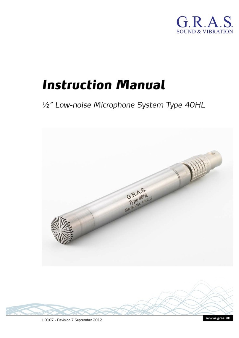
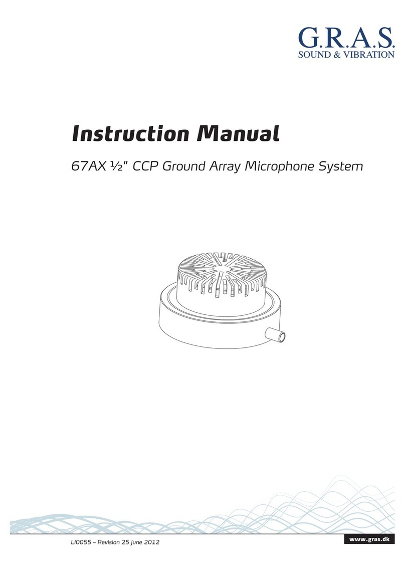
G.R.A.S. 67AX User manual

Instruction Manual

Copyright Notice
© 2011-2018 GRAS Sound & Vibration A/S
http://www.gras.dk
Any technical documentation that is made available by GRAS is the copyrighted work of G.R.A.S.
and is owned by GRAS
The content in this document is subject to change without notice. GRAS Sound & Vibration A/S is
not liable or responsible for any errors or inaccuracies that may appear in this document.
Trademarks
Any other product names mentioned in this document may be trademarks or registered trade-
marks of their respective companies and are hereby acknowledged.
Revision History
Revision Date Description
1 27 May 2011 First publication
2 25 June 2012
3 4 December 2018 In situ-calibration added

Contents
Introduction ...................................................................................................................................................4
Delivered Items ...................................................................................................................................................... 4
Optional Items ........................................................................................................................................................ 4
Assembling the 67 Series System .............................................................................................................5
Calibration ......................................................................................................................................................6
In-situ Level Calibration........................................................................................................................................6
On-site Frequency Calibration ............................................................................................................................7
Seperate Level Calibration after Dismantling..................................................................................................7
Technical Specifi cations..............................................................................................................................8
Dimensions and Data for 67AX ........................................................................................................................... 8
Dimensions and Data for 67AD............................................................................................................................9
Ordering Information ................................................................................................................................. 10
Accessories............................................................................................................................................................10
Warranty and Repair ................................................................................................................................... 10
Calibration ..............................................................................................................................................................10
Warranty..................................................................................................................................................................10
Service and Repairs .............................................................................................................................................10

Introduction
•
•
Delivered Items
Set Item Part Number
Mounting plate
Windscreen
Optional Items
Set Item Part Number

Assembling the 67 Series System
Place the small O-ring in the ridge in the center hole.
Arrange the cable attached to the microphone in the cavity surrounding the mounted micro-
Place the large O-ring in the ridge near the edge of the cavity. The large O-ring must lie on top
of the cable.
screws.
1
2
3
4
5
(× 8)
Fig. 1. A view of the order for assembling the parts of the 67AX/67AD.

Calibration
In-situ Level Calibration
what can be achieved with dismounting the microphone and calibrating it separately.
Items to use
•
•
Procedure
1. Mount the calibration adapter it as shown below
2. Hold the pistonphone steady while centering the opening in the adapter over the microphone.
3.
it will go. Also ensure that you hold the pistonphone upright.
G.R.A.S.
Pistonphone
Type 42AP
Serial No. XXXXX
IEC 60942 (2003) LS
Lock
Signature Series
G.R.A.S.
Pistonphone
Type 42AP
Serial No. XXXXX
IEC 60942 (2003) LS
Lock
Signature Series
RA0216 Calibration Adapter Kit
42AP Pistonphone
Ground plate
Fig. 2. How to mount and use the calibration adapter holder.
Consult the manual for your pistonphone on how to correct for the static pressure.

On-site Frequency Calibration
For on-site frequency calibration the RA0310 Actuator Connector is needed. It is an electrostatic
needed.
Items to use
• RA0310 Actuator Connector.
• GRAS 14AA Actuator Supply.
• A signal generator.
Procedure
1.
2. Connect the 14AA Actuator Supply and signal generator as shown below. The RA0310 must be
connected to the high-voltage output of the 14AA.
3. Perform the calibration .
14AA Actuator Supply
Power
G.R.A.S.
Actuator Supply
Type 14AA
AC Output
+200VDC
AC Output
Max. 1Vrms
+800VDC
AC Output
On
GND
AC Input
Overload
Signal generator
RA0310 Actuator Connector
Ground plate
Fig. 3. Mounting and connecting the RA0310 Actuator Connector.
Separate Level Calibration after Dismantling
The microphone can be calibrated separately after dismounting from the ground plate. For com-
Remove the microphone from the mounting plate.
1.
2. Mount the pistonphone calibration adapter (RA0221) on the pistonphone.
3. Insert the microphone into the adapter on the pistonphone. Press gently to ensure that the
microphone is inserted as far as it can go.
4. Turn on the pistonphone and calibrate as described in the instruction manual for the piston-
phone.

Technical Specifi cations
Dimensions and Data for 67AX
Dimensions
Microphone
Housing
Microphone set height
Without grid
With
Weight
Mounting Plate
Frequency response for the set
Nominal sensitivity for the set
Dynamic range for the set
Thermal noise
Temperature
Operation
Storage
Static-pressure coeffi cient
Humidity (non-condensing)
Range
Venting Rear-vented

Dimensions and Data for 67AD
Dimensions
Microphone
Housing
Microphone set height
Without grid
With
Weight
Mounting Plate
Frequency response for the set
Nominal sensitivity for the set
Polarization voltage
Dynamic range for the set
Thermal noise
Temperature
Operation
Storage
Static-pressure coeffi cient
Humidity (non-condensing)
Range
Venting Rear-vented

Ordering Information
67AX – Included Items Part Number
67AD – Included Items Part Number
Accessories
Item Part Number
Warranty and Repair
Calibration
product. The calibration information is also stored in the built-in TEDS.
Warranty
All GRAS products are made of high-quality materials that will ensure life-long stability and
Service and Repairs
All repairs are made at GRAS International Support Center located in Denmark. Our Support
damage is the result of negligent use or other violations of the warranty. All repairs are delivered
GRAS Sound & Vibration continually strives to improve the quality of
accessories are subject to change.
WEEE directive:
2002/96/EC
CE marking directive:
93/68/EEC
Manufactured to conform with:
RoHS directive:
2002/95/EC
Other manuals for 67AX
1
This manual suits for next models
1
Table of contents
Other G.R.A.S. Microphone System manuals