GAC EEG7000 User manual

1
Governors America Corp. © 2021 Copyright All Rights Reserved
EEG7000 Electronic Digital Governor with GACong Tool 2021-D4 PIB1009
1
2
PERFORMANCE
Isochronous Operation ± 0.25 %
Speed Range 100 - 12 kHz
Droop Range 0.1 - 25 % regulation
Speed Ramp Time
Acceleration. Adj. Range 25 to 2000 RPM/s
Deceleration. Adj. Range 25 to 2000 RPM/s
Starting Fuel Adjustment
Actuator Ramp Rate 1 to 100 %
Actuator Begin Point 0 to 100 %
Overspeed Set Point 400 to 6000 RPM
Crank Termination Set Point 100 to 1000 RPM
Speed Switch Adjustment Range 1000 - 100000 Hz
Speed 1 0 to 6000 RPM
Speed 2 & 3 150 to 6000 RPM
Reverse Power Protection Yes
Transient Voltage Protection 60 V DC
Load Share / Synchronization Input 0 - 10 V DC
(5 V Nominal, Selectable
Polarity, 145 Hz / V Sensitivity)
Speed Sensor Signal Input 1.0 - 60.0 V RMS
Speed Switch (SSW) Rated to 2 A DC
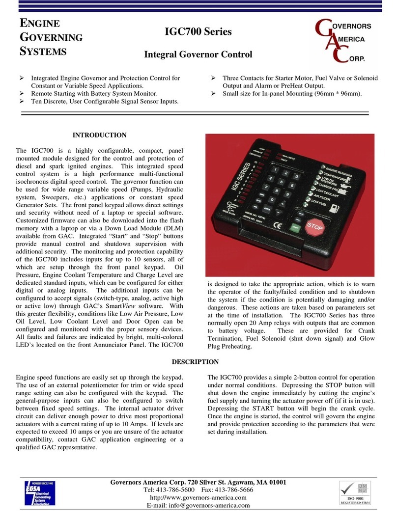
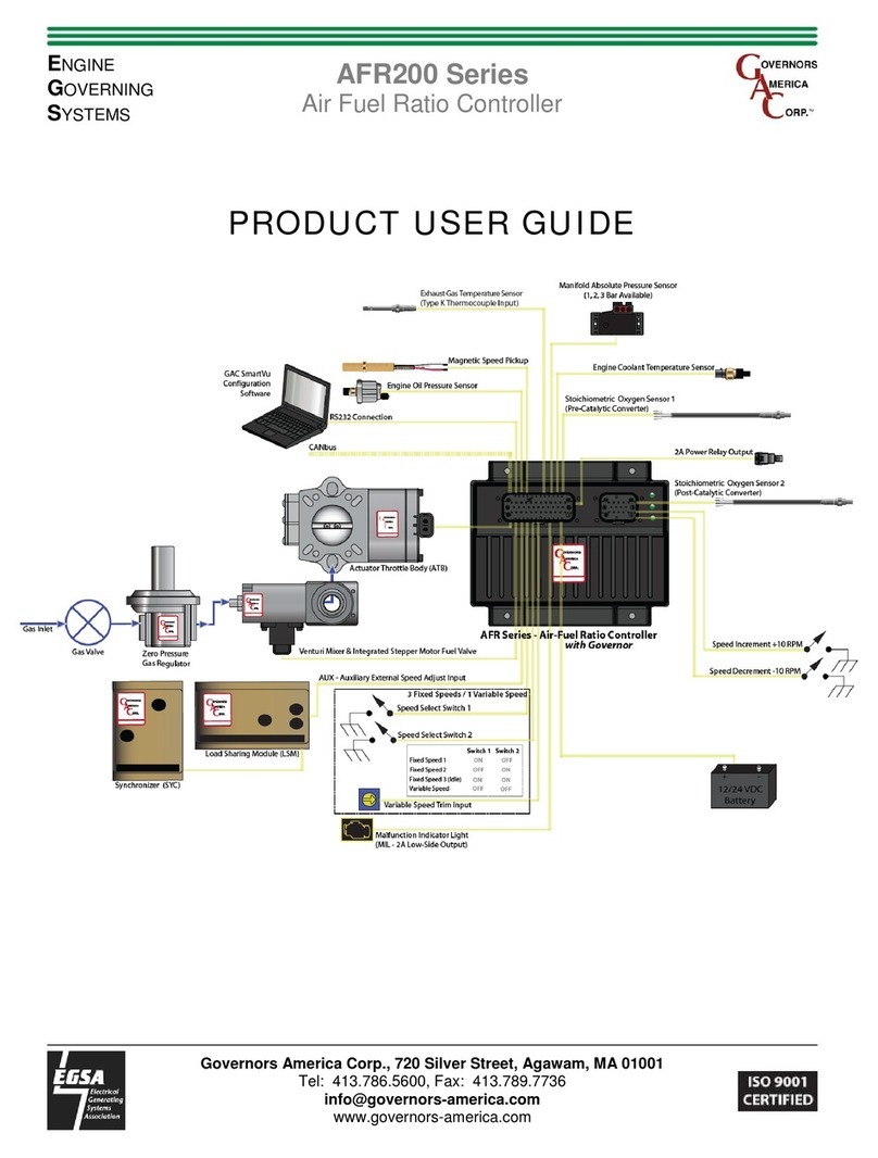
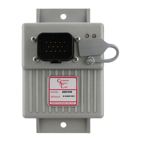
GAC’s EEG7000 electronic digital speed controller is designed to regulate engine speed on
diesel and gaseous fueled engines. When paired with a GAC actuator the EEG7000 is a suit-
able upgrade for any mechanical governor system that needs exibility, precision, and accurate
control of governed speed.
The EEG7000 is designed for industrial engine applications including generator sets, me-
chanical drives, pumps, compressors and off-road mobile equipment. The GACong Tool
adds the ability to monitor and set parameters from your PC. With CAN J1939 capability it
has the ability to accept TSC1 messages over USB as a mini engine control module (ECM).
It can be controlled directly over J1939 with aftermarket displays such as ComAp, Dynagen,
and Murphy – a solution for every application.
Mini-ECU, J1939 TSC1 Control capable with Diagnostic Messages (DM)
Isochronous, variable, or customizable droop governing
3 xed speeds or variable speeds with Direct 0 – 5 V DC, 5 kΩ, or 4 – 20 mA Input
Built-in USB port for easy conguration with free software
Black smoke reduction, speed ramp control, load sharing/synchronizing option,
Cummins EFC-capable
Built-in speed switch output for crank or overspeed
Battery voltage, engine hour meter and service timer
Fully sealed, IP67
Multi- V DC
Gaseous or Diesel
Built-In Congurable Speed Switch Output
ENVIRONMENTAL
Ambient Temperature -40 to 85 °C [-40 to 180 °F]
Relative Humidity up to 90 % non-condensing at 38 °C
Vibration 4 g, 20 - 1000 Hz
Shock Per J1455
Testing 100 % Functional Testing
All Surface Finishes Fungus Proof and Corrosion Resistant
ELECTRICAL
Power Supply 12 - 24 V DC Battery Systems
Continuous Supply Voltage 6.5 to 32 V DC
Polarity Negative Ground (Case Isolated)
Power Consumption 100 mA (No Actuator Current)
Actuator Current 6 A Continuous, 8 A Peak
COMPLIANCE / STANDARDS
Agency CE and RoHS Requirements
Communications USB, RS-232-C, SAE J1939
PHYSICAL
Dimension See Section 3, Installation,
Weight 8 ozf [227 gf]
Mounting Any position, Vertical preferred

2
Governors America Corp. © 2021 Copyright All Rights Reserved
EEG7000 Electronic Digital Governor with GACong Tool 2021-D4 PIB1009
3
Before you begin, note the following required items:
A Windows 7 or better computer with USB port and
Internet connection
14-pin connector (GAC EC1502) or cable harness
assembly (CH1520)
Mount in a cabinet, engine enclosure, or sealed
metal box.
Vertical orientation allows for the draining of uids
in moist environments.
Avoid extreme heat. Do not mount next to turbo-
charger, exhaust manifold, or other high tempera-
ture equipment.
An overspeed shutdown device, independent of the governor system, should be used to prevent loss
of engine control which may cause personal injury or equipment damage.
Do not rely exclusively on the governor system electric actuator to prevent overspeed. A secondary
shutoff device, such as a fuel solenoid must be used.
4
LED COLOR DEFINITION
1 SOLID GREEN Controller is powered on
2 OFF No faults, system is working properly
2SOLID YELLOW Warning: Engine service due, or other
warning as displayed in the GACCong
Tool. If using J1939 see the J1939 CAN
INFO / DIAGNOSTIC TROUBLESHOOT-
ING CODES (DTC) section in this guide.
2 BLINKING RED Actuator current high, shutdown and retry
in 30s.
2 SOLID RED System shut-down:
• Actuator current exceeds 8.0 A for 12
ms continuously
• Engine speed drops or rises faster
than 25 kHz/s
• Engine speed exceeds overspeed
• User commanded engine shutdown
• Incompatible hardware
• Loss of magnetic pickup signal
Error messages display in the GACong Tool, and on the controller itself as LED displays.
in
[mm]

3
Governors America Corp. © 2021 Copyright All Rights Reserved
EEG7000 Electronic Digital Governor with GACong Tool 2021-D4 PIB1009
5
14-pin AMPSEAL requires GAC mating connector kit EC1502 or cable harness CH1520.
Use a crimping tool to connect the connector and harness.
*Pin assignments are not the same as EDG6000.
Review all diagrams and/or additional notes before wiring.
15
6
10
9
14
PIN DEFINITION GAUGE NOTES
1 Actuator (+) 16 Polarity not required for actuator
2Actuator (-) 16
3 Magnetic Pickup (+) 20 * Ground to Pin 12
4Aux Input 20 * 0 - 10 V Range, 5 V Nominal,
Selectable Polarity
5Speed Select A 20 * Ground to Pin 12 to Enable
6 Speed Select B 20 * Ground to Pin 12 to Enable
7 +5.0 Volt Output 20 * Power for external sensors (50 mA)
8 Speed Switch Output 16 * 2A MAX, LSO
9 Variable Speed Input 20 * Potentiometer, 0- 5 V DC or 4 - 20 mA,
selectable polarity
10 Battery Ground (-) 16 Battery ground
11 Battery Power (+) 16
A 10 amp fuse must be installed in the
positive battery lead to protect against any
overload or short circuit or reverse voltage
12
Ground Reference
/ Speed Select
Ground
20 Ground reference for magnetic pick-up (-),
sensors and switches
13 CAN H / RS232 Tx 20 CAN bus or RS-232 congurable through
the GACong Tool
14 CAN L / RS232 Rx 20
Use the GAC mating connector EC1502 or
cable harness CH1520 with the 14-pin AMP-
SEAL with the EEG7000.
Ground the EEG controller case to the en-
gine battery (-).
Wires must be twisted and/or shielded for
their entire length (14 turns per foot). Ground
shield to case.
Minimum gap between speed sensor and
gear teeth is 0.02 in [.5 mm].
The minimum speed sensor voltage is 1 V
AC RMS during crank.
See the product bulletins of the equipment
you are connecting to for more detailed wir-
ing information on those items.
Values are assigned to the wiring parameters
using the GACong Tool.
WIRING RECOMMENDATIONS

4
Governors America Corp. © 2021 Copyright All Rights Reserved
EEG7000 Electronic Digital Governor with GACong Tool 2021-D4 PIB1009
6
PIN 3 - MAGNETIC SPEED PICK-UP
A magnetic speed sensor detects when ring gear teeth pass the tip of the magnetic speed sensor. The output signal is an AC sine wave
whose frequency is converted to crankshaft revolutions per minute (RPM). The following are required:
A magnetic pickup must be installed in the engine bell housing, ring gear case, or fabricated bracket.
All wires must be twisted and/or shielded for their entire length (14 turns per foot).
Ground shield to case. Do not tie case to ground.
The magnetic speed sensor voltage should be at least 1 V RMS while cranking. During operation, 5 to10 V RMS is recommend-
ed.
If the EEG7000 detects no input from the magnetic pickup, the EEG sets the actuator to 0 V DC and the speed to 0 RPM. If the
EEG detects loss of magnetic pickup, LED 2 turns solid red and the system must be reset.
To reset the EEG, cycle DC power.
The magnetic speed sensor connections MUST BE TWISTED AND/OR SHIELDED for their entire length.
The speed sensor cable shield must only be connected to the case. The shield should be insulated to ensure that no other part
of it comes into contact with engine ground, otherwise stray signals may be introduced into the speed switch.
Minimum gap between speed sensor and gear teeth is 0.02 in [.5 mm]. When the engine is stopped, adjust the gap between the
magnetic speed sensor and the ring gear teeth. Usually, backing out the speed sensor 3/4 turn after touching the ring gear tooth
will result in a satisfactory gap.
EEG7000
Aux accepts signals from:
GAC accessories
Auto synchronizers
Load sharing units
Other governing accessories
The auxiliary (AUX) pin accepts input signals from load sharing units, auto synchronizers, and other governor system accessories. The
AUXILIARY input from Pin 4 is activated by selecting Auxiliary Enable in the GACong Tool Advanced Governor Settings menu and
selecting the desired Auxiliary Polarity.
The AUX function decreases engine speed with increasing input voltage, the polarity shift function increases engine speed with increas-
ing input voltage. Aux input is nominally 5.0 V +/- 5.0 V DC.
PIN 4 - AUXILIARY INPUT

5
Governors America Corp. © 2021 Copyright All Rights Reserved
EEG7000 Electronic Digital Governor with GACong Tool 2021-D4 PIB1009
WIRING COMBINATIONS
PIN 5 PIN 6 Speed Mode
Open Open Variable Speed (or Fixed Speed)
Ground Ground Fixed Speed 1
Open Ground Fixed Speed 2
Ground Open Fixed Speed 3
PINS 5 AND 6 - SPEED SELECT
The EEG7000 has two inputs which, in various combinations, allow the user to use three xed speed settings or the variable speed set-
ting. This is accomplished by tying inputs to ground or leaving them open. Fixed Speed 1 can be set to idle as required.
Speed is set from the GACong Tool on the Engine Tuning menu in the
Fixed Speed and Variable Speed blocks.
To set variable speed, select the analog mode for your variable
input signal, and input desired RPM. See Section 10, Setting Vari-
able Speed Parameters bulletin for more details.
The Analog 1 minimum and maximum settings can be
automatically calibrated using Calibrate Minimum or Calibrate
Maximum.
To calibrate the minimum percent set the potentiometer to the
desired start value and click the Calibrate Minimum button. To
calibrate the maximum percent set the potentiometer to the
highest end value and click Calibrate Maximum button. The
difference between the analog minimum speed settings will be at
least 25 % to prevent rough idle.
6
Pin 7 provides analog input from external trim or variable speed potentiometers. It is also used to create resistive Input: (Select 0 - 5V
/ Resistive). Connect a 5 k Ω potentiometer between Pins 7, 9 and 12 as shown under Variable Speed.
PIN 7 - ANALOG INPUT
When the EEG7000 detects engine speed has reached the user dened Limit / Threshold value, the EEG7000 controller changes the
state of Pin 8. The SSW can be used for overspeed protection, starter cutoff (crank termination), and other general auxiliary functions.
The SSW adjustment range is 100 to 6000 RPM. The default value is 1800 RPM and the default state (Mode) is NORMALLY
OPEN.
When NORMALLY OPEN is selected the SSW output on Pin 8 will energize at the set speed. When NORMALLY CLOSED is
selected output from Pin 8 will de-energize at the speed setting.
When the LATCHING box is checked the SSW output state is xed until power to the unit is cycled. When the box is not checked
the output state automatically resets at 0 RPM. The default is checked (ON).
PIN 8 - SPEED SWITCH OUTPUT (SSW)

6
Governors America Corp. © 2021 Copyright All Rights Reserved
EEG7000 Electronic Digital Governor with GACong Tool 2021-D4 PIB1009
Analog variable speed is enabled when Pins 5 and 6 are not grounded.
Connect a 5 kΩ potentiometer,0 - 5 V DC or 4 - 20 mA speed input signal,to
Pin 9. The default setting is 0 - 5 V DC with variable speed available.
Variable Speed Analog 1 Mode in the GACong Tool must be set to 0-5 V
DC or 4-20 mA to use this function.
Setting variable speed requires a potentiometer, available from GAC. A
potentiometer calibration within the GACong Tool characterizes the
selected potentiometer.
Variable Speed can be used as another xed speed setting if both Speed
Minimum and Speed Maximum parameters are set to the same RPM and
no potentiometer is connected.
For more details on setting variable speed see Section 10, Setting Variable
Speed Parameters.
PIN 9 - ANALOG VARIABLE SPEED
Setting the Minimum Speed and Maximum Speed to the same
value with no input on Pin 9 enables you to use Variable Speed
as an additional xed speed setting.
The CAN bus must be terminated at both ends by a 120Ω resistor.
Use cable harness CH1520, 7 AWG, or EC1502 mating connector
kit with twisted pair that meets SAE J1939 or SAE J1128 stan-
dards.
PINS 13 AND 14 - CAN H AND CAN L - RS-232
The CAN output supports J1939 protocol for basic engine speed and Diagnostic Trouble Codes (DTCs). More on the diagnostic trou-
ble codes (DTCs) detailed in section 17 J1939 CAN Settings and Diagnostics in this bulletin.
6
NOTE
Digital variable speed is enabled when Pins 5 and 6 are not grounded. Connect a 5 kΩ
potentiometer,0 - 5 V DC or 4 - 20 mA speed input signal,to Pin 9. The default setting is
0 - 5 V DC with variable speed available.
Variable Speed Analog 1 Mode in the GACong Tool must be set to 0-5 V DC or 4-20 mA
to use this function.
Setting variable speed requires a potentiometer, available from GAC. A potentiometer
calibration within the GACong Tool characterizes the selected potentiometer.
Variable Speed can be used as another xed speed setting if both Speed Minimum
and Speed Maximum parameters are set to the same RPM and no potentiometer is
connected.
For more details on setting variable speed see Section 10, Setting Variable Speed
Parameters.
PIN 9 - DIGITAL VARIABLE SPEED

7
Governors America Corp. © 2021 Copyright All Rights Reserved
EEG7000 Electronic Digital Governor with GACong Tool 2021-D4 PIB1009
7onfig
1. Download the GACCongx.zip le from the governors-america.
com software download page. Depending on your network, the
installer may ask for additional information. After installation your
PC will require a restart.
2. The zip le is saved to the PCs default download area, unless
you tell it otherwise. Once downloaded, double-click the le
name to start the installation. You may need to double click again
on the EEG7000 IT setup.exe le to actually begin the installa-
tion.
3. The Welcome screen displays. Click Next. Note the default
installation is in the Governors America Corp program les area.
4. Click Next. Allow the installation to create a desktop icon. You
can also create a quick Launch icon.
5. Click Next. The installation will create a Governors
America Corp startup folder location. Click Next.
Click Install at the next screen. Click Finish when
complete. The GACong icon is placed on the
desktop.
6. Connect the EEG7000 to the PC using a USB-A port and con-
nect the USB-B port on the EEG7000. Power for the controller
comes from the engine battery. Ensure the system is powered.
Do not start the engine.
7. Double-click the GACong Tool icon on your desktop. On rst
use, when prompted, select EEG7000 from the drop-down list.
8. Click OK to launch the tool.
9. Connect the GACong Tool to the EEG7000 by clicking on the
Connect icon on the top left of the GACong window.
10. A pop-up dialogue window displays a drop-down list of available
comm ports. Select the appropriate port and click OK. If you are
unsure of the comm port, use the Windows Device Manager to
locate what device is plugged in to which USB port.
11. The Connection Status indicator on the lower left corner of
GACong Tool window ashes yellow then turns green as the
connection is completed. The status bar displays Connected. If
the connection does not complete, a red Disconnected message
displays. Check your connections and note any error messages
on the PC and try again.
INSTALLING GAC TOOL AND CONNECTING TO EEG7000
Power for the EEG7000 comes from the engine battery.
REMINDERREMINDER
EEG7000 speed controller uses the GACong Tool to update parameter values on the EEG7000, adjust performance settings, and view
results. This PC tool provides a menu-driven user-friendly interface to update settings, and speed diagnostics and troubleshooting.
The tool also allows you to set up multiple scenarios and save them for use later or for sharing with other sites using the EEG7000.
The GACong Tool is downloaded from GAC’s website. A PC with at least Windows 7, one USB port and an internet connection is
required.
A 14 pin connector (GAC EC1502) or cable harness assembly (CH1520) is also required. An RS-232 port connection is required, since
many computers do not have this port, use a USB-to-RS-232 converter will be required. GAC recommends GAC part number EAM204.

8
Governors America Corp. © 2021 Copyright All Rights Reserved
EEG7000 Electronic Digital Governor with GACong Tool 2021-D4 PIB1009
8onfig
EEG7000 speed controller uses the GACong Tool to set parameters on the EEG7000, adjust performance settings, and view results.
Parameters are grouped by functionality at the Main menu. Parameters are grouped by functionality at the Main menu. Initial setup is
completed from Engine Tuning on the main menu.
Tool bar
Main menu is
arranged by
function
Connection status
shows the GACong
Tool connection sta-
tus to the EEG7000
Current Engine status
and EEG7000 set-
tings are displayed in
real-time.
Click STOP to disengage
the engine from the
EEG7000 and set engine
speed to 0 RPM.
Update parameter values by double-clicking the underline or existing value next to a parameter name. Type in the new value and
click Enter to save the change. A green checkmark next to the change indicates the change was successful. No check or a red or
yellow warning icon indicates the change was not saved or caused a conict with another setting.
For a short description of a parameter, hover the cursor over the parameter name and a description briey displays, or reference
the item in the Adjustment menu where a short description is available in its associated menu tab.
Errors and parameter information display when you change a value. Read all RED warning boxes error information, yellow
cautions, and other pop-up information. Setting some parameter values impact other parameter values, often displaying a caution.
The GACong Tool windows automatically sizes windows to t the window size.
While using the tool, note the far right screen engine status bar, showing Engine Status information.
Selecting STOP sets the engine speed to 0 RPM and shuts down the EEG7500 controller. It does not shut down the engine directly.

9
Governors America Corp. © 2021 Copyright All Rights Reserved
EEG7000 Electronic Digital Governor with GACong Tool 2021-D4 PIB1009
8onfig
The Main menu is divided by function. The Dashboard and Engine Status as well as the right hand Engine Status panel show the engine
status. The menus are:
includes basic setup of initial and system safety settings including control mode (based on actuator type) over-
speed, ywheel, fuel settings and acceleration rates. Engine Tuning also includes xed speed settings, PID (Gain, Stability, Dead-
time) tuning, Variable Speed setup. A fuel limiting table can also be built here.
allows for automatic or manual conguration of the feedback sensor.
include the auxiliary settings, droop, and speed trim.
assigns speed and position switches, and output devices.
connects with output routing, diagnostic messaging and TSC1/J1939.
ENGINE TUNING
OUTPUT CONFIGURATION
Engine Tuning is the basic menu used to store your engine startup
and tuning information.
Flywheel teeth, overspeed, fuel limit
Start fuel rate, Fuel ramp rate, starter cutoff, acceleration and
deceleration
Fixed speeds
Variable speed settings
PID Tuning (Gain, Stability, Deadtime)
Lead circuit, Lightforce Governing, Speed anticipation
Fuel Limit Table
Output conguration allows the EEG7000 to connect to speed
switches.
ADVANCED GOVERNOR SETTINGS
The Advanced Governor Settings menu lets you:
AUX enable, aux polarity
Droop
COMMUNICATION
ADJUSTMENTS
The communication menu lets you:
Set the base Internet address type, either CAN or RS232
Set J1939 information and base settings
Acknowledge error messages
Map routing between the EEG7000 and the J1939 system
The adjustments menu includes all the parameter settings for the
EEG7000 available in the GACong Tool. This menu allows you to
set all the parameter settings from one place. Parameters are on the
following tabs:
Tuning
J1939
Run Time Meters
Speed Switches
Actions
Information

10
Governors America Corp. © 2021 Copyright All Rights Reserved
EEG7000 Electronic Digital Governor with GACong Tool 2021-D4 PIB1009
Wiring between the engine, the EEG7000 speed unit, and the actuator should be completed before starting the engine. See Sections
5 and 6 for more wiring details. The following are the minimum wiring requirements:
Connect Actuator to EEG7000 (Pins A and B)
Connect Actuator to magnetic pickups (Pins 1 and 2)
Connect EEG7000 to battery (Pins C and D)
Connect USB from EEG7000 to PC
The EEG7000 can be set up and used straight out of the box, with an actuator attached, using default settings. This section details
the initial installation and setup using the default settings. Wiring between the engine and the EEG7000 is required, and reviewing this
document and default settings is advised.
There are two sets of parameters to work with: basic engine performance and engine tuning. Getting Started gets your engine started.
Engine Tuning improves performance.
Before you start your engine:
Install the GACong Tool on a PC and connect the PC to the EEG7000 with the USB cable
Provide power to the EEG from the battery.
Install an actuator between EEG7000 and engine, following your actuators Installation Manual.
Set the following minimum settings in the GACong Tool on the Engine Tuning menu:
• Overspeed for automatic actuator shutdown
• Number of engine ywheel teeth
• Fuel Limit
• Acceleration and Deceleration
• Actuator Ramp Rate
• Starter Cutoff
• Fixed Speed Settings
Once the parameter settings are reviewed and values updated as required, reconnect your fuel supply and start your engine.
1. Reconnect the fuel supply.
2. Crank the engine with DC power applied to the governor system. The engine should be at operating speed with no load.
3. The actuator/ fuel to the engine will be positioned to the level set by the Actuator Start Fuel (default is maximum fuel). Actuator Ramp
Rate controls the rate at which fuel is increased to start the engine, 10% by default.
4. If the engine is unstable after starting, open the GACong Tool and adjust the Gain, Stability, and Deadtime in the Engine Tuning menu
in the PID Tuning block, until the engine is relatively stable.
5. Once the engine is stable you can connect additional devices and further tune your engine.
Do not rely exclusively on the governor system electronic actuator to prevent overspeed. A secondary shutoff
device, such as a fuel solenoid must be used. STOP ENGINE shuts down the actuator, not the engine.
FIXED SPEED SETTINGS
PARAMETER RANGE DEFAULT DEFINITION
Speed 1 0 - 6000 1500 Selects one of three xed speeds (RPM).
Speed 2 and 3 150 - 6000 1500
Gain 1,2 and 3 1 - 100 50 Set one Gain value for each xed speed.
At the GACong Tool:
1. At the Main menu select Engine Tuning.
2. Note if the Flywheel Teeth value is correct for you engine. If not, double click on
the value and change it. Click Enter.
3. Enter values for all the all Set-Up and Start-Up parameters.
4. In the same menu, enter the Fixed Speed Settings values for Speed 1, Speed
2, and Speed 3.
5. Gain, Stability, and Deadtime can also be set here.
Further descriptions on these and all parameters are in section 15, GAConfig TOOL - SETTING ALL PARAMETERS
9
MINIMUM WIRING SETUP
START YOUR ENGINE

11
Governors America Corp. © 2021 Copyright All Rights Reserved
EEG7000 Electronic Digital Governor with GACong Tool 2021-D4 PIB1009
To improve basic performance, with no engine load complete the following:
1. At the GACong Tool open the Engine Tuning menu, and at the PID Tuning block, perform the following:
a. Increase the Gain by entering new value until instability develops. Gradually decrease the Gain until stability returns. Decrease
the adjustment one count further to ensure stable performance.
b. Increase Stability value until instability develops. Gradually decrease Stability value until stability returns. Decrease the value
by one to ensure it is stable. If there is no instability leave set at 50.
c. Set the DEADTIME to Low. If instability develops, change to High.
Once the engine is running at operating speed, with no load, use the GACong Tool to adjust the parameter values to increase engine
stability. Each speed parameter, 1 through 3, has a separate Gain value. The speed selection number and active Gain are shown in the
PID Tuning section.
Stability is achieved by balancing PID: Gain, Stability, and Deadtime.
(proportional) changes the initial response of the speed controller. Increasing gain makes the engine more responsive to
load changes while decreasing gain makes it less responsive to load changes. Avoid engine instability due to high gain when
adjusting this parameter.
(Integral) changes the steady state response of the engine. Increasing stability allows the system to come to steady
state speed faster, while decreasing the stability results in a more gradual transition to steady state speed.
(Derivative) sets the transient response of the engine to high or low and affects stability during transient load changes.
Increasing deadtime decreases the percent of overshoot and settling time during a transient load change while decreasing
deadtime increases them.
Additional adjustments may be required after engine load is applied. Normally, adjustments made at no load
achieve satisfactory performance.
10
Variable speed parameters activate throttle or fuel control relative to the variable speed input signal. This requires a single remote
speed adjustment potentiometer is installed to adjust the engine speed continuously over a specic speed range.
Voltage Input: (Select 0 - 5 V / Resistive) Voltage to 5.0 V, above 5.0 V the variable speed function is clamped at 100%, RPM
response to voltage is linear.
Resistive Input: (Select 0 - 5 V / Resistive) Connect a 5 kΩ potentiometer between Pins 7, 9 and 12 as shown in Variable Speed.
Maximum operating voltage is 5.0 V DC, response to resistive input is linear.
Current Input: (Select 4 - 20 mA) SPEED MINIMUM sets the low speed at 4 mA. SPEED MAXIMUM sets the high speed at 20 mA.
If the input current drops below 4 mA, variable speed is clamped at 0%. If the input current level exceeds 20 mA, variable speed is
clamped at 100%. RPM response to current is linear.
VARIABLE SPEED PARAMETERS
PARAMETER RANGE DEFAULT DEFINITION
Analog 1 Mode 0 - 5 V DC or 4 - 20 mA 0 - 5 V DC Sets the variable speed input for the analog device. Use 0 - 5 V DC for resistive.
Speed Minimum 150 - 6000 RPM 1500 Minimum speed setting
Variable Speed Start Gain 1 - 100 50 PID Gain to use when at the minimum speed while in variable speed.
Speed Maximum 150 - 6000 RPM 1500 Maximum speed setting.
Variable Speed End Gain 1 - 100 50 PID Gain to use when at the maximum speed while in variable speed.
Analog 1 Minimum
(Calibrate button) 0 - 75 % 0*
Sets the range for the minimum variable speed. Range: 0 to 75 % and must be
25% apart from end position. This can be calibrated automatically by clicking
Calibrate Minimum.
Analog 1 Maximum
(Calibrate button) 25 - 100 % 100*
Sets the range for the maximum variable speed. Range: 25 to 100% and must
be 25% apart from start position. This can be calibrated automatically by clicking
Calibrate Maximum.
Analog 1 Actual 0 - 100 % 100 Status of the current variable speed input position.
*Setting % RPM and 100 % RPM
9
NOTE
ADJUSTING BASIC STABILITY WITH FIXED SPEED

12
Governors America Corp. © 2021 Copyright All Rights Reserved
EEG7000 Electronic Digital Governor with GACong Tool 2021-D4 PIB1009
0 - 5V Input To Pin 9 4 - 20mA Input To Pin 9
HertzMAG PICKUP = (RPM x #Teeth)
60
RPM = (HertzMAG PICKUP x 60)
#Teeth
1. Review the Engine information block on the far right of the
GACong Tool screen to make sure Selected Speed Mode displays as Variable. Variable
Speed is set when Pins 5 and 6 are not grounded and a 5 kΩ potentiometer is available
from Pin 9. See wiring table and diagram starting in Section 5 for details on potentiometer
wiring.
2. Open the GACong Tool.
3. At the Engine Tuning menu, in the Variable Speed box, select the Analog 1 Mode from the
dropdown menu (voltage, resistive, or current input) that corresponds to your actuators input
signal.
4. If using resistive input, set the potentiometer in the full counter-clockwise position.
5. Set Speed Minimum.
6. Set Variable Speed Start Gain to optimize minimum gain.
7. Analog 1 Minimum and Maximum can be set manually or automatically using the calibrate
buttons.
a. To set automatically, select the Calibrate Minimum button.
b. To set manually, set Analog 1 Minimum values between 0 to 75 %
NOTE: The tool will reset any values that are not 25% apart to the closest valid number.
8. If using resistive input, set the potentiometer in the full clockwise position.
9. Set the Speed Maximum.
10. Set Variable Speed End Gain to optimize maximum gain.
11. To maintain engine stability at the minimum speed setting, add a small amount of droop using
Droop in the GACong Tool Advanced menu. At the maximum speed setting performance will
be near isochronous, regardless of the droop adjustment setting.
SETTING VARIABLE SPEED SETTINGS
If the Minimum Speed setting is higher than Maximum Speed, increasing the speed input signal / potentiometer posi-
tion will decrease RPM.
Minimum Speed and Maximum Speed setting ranges are 150 to 6000 RPM with default value of 1500 RPM.
Gain, Stability, and Deadtime values may need adjustment after engine load is applied.
Normally adjustments made at no load achieve satisfactory performance.
If further performance improvements are required, see Section 18, Troubleshooting, in this guide.
NOTE
NOTE
10

13
Governors America Corp. © 2021 Copyright All Rights Reserved
EEG7000 Electronic Digital Governor with GACong Tool 2021-D4 PIB1009
11
Droop adjustments are made while the engine is running. Setting droop reduces the
speed as fuel position (load) increases.
To maintain engine stability, at the minimum speed setting, add a small amount of
droop. At maximum speed performance will be near isochronous regardless of the
droop adjustment setting.
1. Open the GACong Tool on your PC. From the Main menu, select Engine Tuning
and locate the PID Tuning box.
2. Check that Lead Circuit is set to Off. The default is On.
3. From the Main menu select Advanced Governor Settings and locate the Droop box.
4. Set No Load Current to the measured / displayed current value when operating at
no load rated speed (default value is 0.5 A.).
5. Set Full Load Current to the measured / displayed current value when operating at
full load rated speed (default value is 6.0 A.) (NFSC controller).
6. Set Droop to the desired settings for each of the three xed speeds and one vari-
able speed as needed.
The No Load Current value must be set to less than Full Load Current and the difference between the two
must be at least 0.5 A.
If an invalid combination is entered a warning message displays and the default to 0.5 A and 6.0 A.
Use the Speed Switch Output parameters to receive information
from sensors for low and high speed settings as well as other speed
parameters.
The SSW’s range of adjustment is 100 to 6000 RPM. The default value
is 1800 RPM and the default state is NORMALLY OPEN.
1. From the GACong Tool Main menu, select Speed Switches and
navigate to the Speed Switch Output box.
2. At Limit / Threshold set the RPM limit for speed switch 1 output.
3. From Mode, select one of the following from the drop down menu:
NORMALLY OPEN output from Pin 8 energizes at the set RPM.
NORMALLY CLOSED output from Pin 8 de-energizes at set
RPM.
4. Select LATCHING (On) to the SSW output state to xed until power
to the EEG7000 is cycled. When the box is not checked the output
state automatically resets to the Limit/Threshold RPM to 0 RPM
after power cycle to the system.
12
NOTE

14
Governors America Corp. © 2021 Copyright All Rights Reserved
EEG7000 Electronic Digital Governor with GACong Tool 2021-D4 PIB1009
1. In the GACong Tool tool bar, select Data Plot.
2. Set the Time Range (in seconds).
3. Click Start. The data displays similar to shown below. Note the
time and RPMs display when you move your cursor over the
green timeline.
4. To save the data, click the Save button. The le is saved as a
printable graphic (lename.png) le.
Data Plot displays real-time engine data with RPM and actuator duty cycle versus time. The cursor aligns the engine speed and duty
cycle plots to display a time relationship.
13
Factory default settings can be restored using the on the something tab of the Adjustments menu. The factory default
settings are restored. Click on the Main menu and the view screen will update with the factory default settings. Factory
restore can be done when the engine is off but the GACong Tool is running.
To complete a Factory Restore, rst export your current settings and save to a local computer to allow you to compare settings at a later
date.
14

15
Governors America Corp. © 2021 Copyright All Rights Reserved
EEG7000 Electronic Digital Governor with GACong Tool 2021-D4 PIB1009
ADJUSTMENTS
PARAMETER MIN - MAX DEFAULT NOTES
Set-Up
Flywheel Teeth 60 - 250 120 Number of teeth on the ywheel. The system can govern up to 12000 Hz.
HertzMAG PICKUP = (RPM x #Teeth) ÷ 60
Overspeed 150 - 6000* 1800 RPM set to cause automatic actuator shut down. Set this value low enough to prevent
mechanical damage but high enough to allow realistic load rejection speeds without
stopping the engine. Begin by setting at no more than 25% above rated speed.
Fuel Limit 0 - 100 % 100 Maximum fuel (actuator duty cycle) allowed during governing. Use this parameter to
prevent over fueling after the engine has started. During normal starting cycles and short
load step the function will not engage since there is a 1 second delay.
Actuator Start Fuel 0 - 100 % 100 Actuator start point during cranking.
Actuator Ramp Rate 1 - 100 %/s 10 Fuel (actuator duty cycle) ramp rate during cranking.
Starter Cutoff 100 - 1000 RPM 400 Crank termination speed in RPM.
Acceleration 25 - 2000 RPM/s 300 Controls rate of acceleration in engine speed. A lower value RPM/s allows for a gradual
increase in engine speed while a larger value of RPM/s provides faster acceleration
Deceleration 25 - 2000 RPM/s 300 Controls rate of deceleration in engine speed. Lower RPM/s allows for a gradual de-
crease in response to engine speed while higher RPM/s create more rapid deceleration.
Speed 1
Speed 2, 3
0 - 6000*
150 - 6000*
1500
1500
Set engine speeds.
Analog 1 Mode 4-20 mA or
0-5 V DC
0-5 V DC/
resistive
Sets variable speed input signal (Analog 1 Mode) to 0-5 V DC/Resistive or 4-20 mA
Speed Minimum
Speed Maximum
150 - 6000*
150 - 6000*
1500
1500
Minimum and maximum speed settings.
Variable Speed Start Gain
Variable Speed End Gain
1 - 100
0 - 100
50
50
PID Gain to use when at the minimum speed while in variable speed.
PID Gain to use when at the maximum speed while in variable speed.
Analog 1 Minimum
(Calibrate button)
0 - 75 %. Must
be 25% apart.
0 Sets the variable input start position based on the current value. Range: 0 to 75 % and
must be 25% apart from end position. Use the Calibrate button to set this automatically.
Analog 1 Maximum
(Calibrate button)
25 - 100 %. Must
be 25% apart.
100 Sets the variable end position based on the current value. Range: 0 to 75 % and must
be 25% apart from end position. Use the Calibrate button to set this automatically.
Gain 1, 2, 3 1 - 100 50 Gain determines how fast the controller responds to transient load changes or when a
load disturbance occurs.
Stability 0 - 100 50 Stability changes the steady state response of the engine. Increasing stability allows the
system to come to steady state speed faster while decreasing stability results in a more
gradual transition to steady state speed.
Deadtime Low - High High PID deadtime
Lead Circuit On-Off On Lead Circuit increases the range of Gain adjustment increasing the responsiveness of
the governor. Select Lead Circuit with slow or moderate hunting at higher Gain settings.
Light Force Governing On-Off Off Light Force Governor improves resolution when controlling small actuators and low
current including GAC T1 ATB, ALR/ALN, 100/103/104 series and normally closed actua-
tors. This feature can only be changed when the engine is not running.
Speed Anticipation On-Off Off Speed anticipation set to ON reduces RPM recovery time during high load transients and
requires both no load (NLCU) and full load current (FLCU) values are entered.
GAConfig
Selecting the menu gives you access to all the pa-
rameters from one menu location. The parameters are grouped by
function and relate directly to the GACong Tool groupings.
THe adjustments menu does not give you all the error messages the
core menus do. Remember, parameter values may be updated by
the software if they interfere with other related parameters.
15

16
Governors America Corp. © 2021 Copyright All Rights Reserved
EEG7000 Electronic Digital Governor with GACong Tool 2021-D4 PIB1009
GAConfig
15
PARAMETER MIN - MAX DEFAULT NOTES
Auxiliary Enable On-Off Off Controls auxiliary / load sharing function
Auxiliary Polarity Decreasing -
Increasing Speed
Decreasing
Speed
Auxiliary Input Polarity is set to either increase speed with increased voltage or
decreases speed with increased voltage. Aux input is nominally 5.0 V +/- 5.0V
DC.
No Load Current 0 - 5.5 A 0.5 A Actuator current at rated speed, no load.
Full Load Current 0.5 - 6.0 A 6.0 A Actuator current at rated speed, full load (NFSC controller).
Fixed Speed 1, 2, 3, Droop 0 - 25 % 0 Percent of droop (% RPM decrease at full load) to incorporate while associated
xed speed select 1, 2, or 3.
Variable Speed Droop 0 - 25 % 0 Percent of droop (% RPM decrease at full load) to incorporate while in variable
speed mode.
Limit/Threshold 100 - 6000 RPM 1800 Speed limit for speed switch 1 output.
Latching On - Off On Latching set to ON sets the output state ON until power is cycled. With the Latch
setting OFF, the output state of the pin automatically resets at 0 RPM.
Mode Normally Open,
Normally Closed
Normally
Open
Mode sets the output polarity at either normally open or normally closed.
Mode CAN or RS232 Sets the input/output access to CAN or RS-232 communication.
Address 0 - 253 0 Sets the CAN address for J1939 communication
Engine Requested Speed 0 - 6000 RPM 1500 Sets Speed Limit
Engine Override Control
Mode
Disabled-Enabled Disabled Currently unavailable. Will control PGN0 SPN695 Current Torque/Speed Control
1 - Engine Override Control Mode.
Speed Ramping On-Off Off Current TSC1 speed command limit
J1939 Diagnostic Messages --- --- DM1 and DM2 status and reset
Service Timer Enable 0 = Disabled,
1 = Enabled
0* Controls the service timer. *Transitioning from disabled to enabled automatically
sets the service timer to +500 hours
Current Service Hours 1 - 2000 500 Setting service hours sets the hour meter for an alert at the selected service
interval. Hours can be set from 1 to 2000 hours. If the service time is expired, the
displayed number will be ‘0’ or negative.
Reset Service Hours 1 - 2000 500 When the service timer is enabled, resets the service counter to this value
Engine Runtime 0 - 65535.9 Current runtime hours
System Reset Button Performs a software reset of the system. Engine speed must be 0.
Engine Shutdown Button Software commanded engine shutdown.
Factory Restore Button Restores factory default settings to GACong Tool and the speed controller.
Fault Clear Button Clears fault indicators.
Force DM3 Button Clears all J1939 previously active faults as if a DM3 command was received.
Items in Gray are display only.

17
Governors America Corp. © 2021 Copyright All Rights Reserved
EEG7000 Electronic Digital Governor with GACong Tool 2021-D4 PIB1009
16
PARAMETER VALUE DEFAULT
Mode CAN or RS232 Port enabled
Address 0 - 253 0
Engine Override Control Mode Enabled Enabled
Speed Ramping On / Off On
J1939 CONFIGURATION
Use the GACong Tool to set the J1939 parameters.
1. At the GACong Tool, select the J1939 menu.
2. Choose CAN for the Communication mode
3. Enter the remaining required parameters.
4. Use the Reset Logged Faults button to clear cur-
rent faults.
The EEG7000 is J1939 compatible. After initial conguration the CAN data is available on the J1939 Diagnostics Messages view on
the GACong tool, or using a compatible controller. Sample PGN transmit and receive codes are shown in this section. This docu-
ment does not instruct you on using J1939 and CAN.
CREATING J1939 MESSAGING
J1939 messaging between the EEG7000 and the J1939 source is congured using these basics rules.
• J1939 indexing starts at 1, not 0.
• Timeout rate is 2X transmission rate. Transmission rate is congured using SPN3349 (PGN65251), part of the TSC1 message.
Timeout rate defaults at the 5th byte (0xFE to 40ms). Other values including SPN3344 can be used to set longer timeouts.
• Speed Ramping is used under one of two conditions:
• When not under TSC1 control
• When under TSC1 control and CAN Speed Ramp Enable is set
• Supported PGNs are list in the following sections.
BYTE 1 2 3 4 5 6 7 8
MESSAGE 0xFD 0x00 0x00 0xFF 0xFE 0xFF 0xFF 0xFF
DEFINITION Speed
control
mode
Low
speed
High
speed
Nominal
rate
20ms,
timeout
40ms
EXAMPLE
1600 RPM at 20ms nominal (40 ms timeout)
0xFD 0x00 0x32 0xFE 0xFF 0xFF 0xFF 0xFF
If signal is lost to J1939 the EEG7000 reverts to hardwired xed speed settings (idle).

18
Governors America Corp. © 2021 Copyright All Rights Reserved
EEG7000 Electronic Digital Governor with GACong Tool 2021-D4 PIB1009
SYSTEM FAULTS / J1939 DTC’S
FAULT
CODE
CONDITION J1939 SPN J1939 FMI J1939 LAMP / LED
DISPLAY
ACTION
1 Actuator Overcurrent 638 (Actuator) Current High (6) Protect / Blinking Red Shutdown, retry 30
seconds
2 Loss of Speed Sensor 636 (Speed Sensor) Abnormal Signal (8) Stop / Shutdown Shutdown
3 Overspeed 190 (Engine Speed) Data Above Range (0) Stop / Shutdown Shutdown
4 User Shutdown 1110 (Eng. Shutdown) Data Incorrect (2) Stop / Shutdown Shutdown
241 EEPROM Read 628 (CPU / Memory) Out of Calibration (13) Warning / Solid Yellow None
285 TSC1 Unsupported Mode 695 (Override mode) Data Incorrect (2) Warning / Solid Yellow Revert to selected speed
286 TSC1 Message Rate Error 3349 (Message Rate) Data Incorrect (2) Warning / Solid Yellow Revert to selected speed
287 TSC1 Message Count Error 4206 (Message Counter) Data Incorrect (2) Warning / Solid Yellow Revert to selected speed
288 TSC1 Speed Request Invalid 898 (Requested Speed) Data Incorrect (2) Warning / Solid Yellow Revert to selected speed
289 TSC1 Invalid Checksum 4207 (Checksum) Data Incorrect (2) Warning / Solid Yellow Revert to selected speed
290 TSC1 Destination Address 1483 (Source Address) Data Incorrect (2) Warning / Solid Yellow Revert to selected speed
305 Service Due 916 (Service Delay) Data Incorrect (2) Protect / Solid Yellow None
J1939 CAN INFO / DIAGNOSTIC TROUBLESHOOTING CODES (DTC)
16
PGN NAME VALID SPN’s NOTES
0Torque / Speed
Control 1 (TSC1)
SPN695 - Engine Override Control Mode
SPN898 - Engine Requested Speed / Speed Limit
SPN3349 - TSC1 Transmission Rate
SPN4206 - Message Counter
SPN4207 - Message Checksum
Engine Override mode is not currently sup-
ported (SPN695) system governs at selected
speed.
After inactivity of 2x transmission rate
(SPN3349) the system will revert to governing
at the selected speed.
59904 PGN Request PGN65227 - DM2 (Previously Active Faults) Request
PGN65228 - DM3 (Clear Previously Active Faults) Request
DATA RECEIVED ON J1939 BUS
PGN NAME TRANSMIT
RATE VALID SPN’s NOTES
61444 Electronic Engine Control 1 (EEC 1) 20 ms SPN190 - Engine Speed RPM
61443 Electronic Engine Control 2 (EEC 2) 50 ms
SPN1 - Accelerator Pedal Position 1 (%)
SPN2 - Percent Load at Current Speed
(%)
SPN91 is sourced from the variable
sped input position.
SPN92 is calculated based on no
load (NLCU) and full load (FLCU)
parameters
64914 Engine Operating Information (EOI) 250 ms SPN3543 - Engine Operating State
SPN3607 - Engine Emergency Shutdown
65252 Shutdown (SHUTDN) 1000 ms SPN2814 - Engine Alarm Output
SPN1110 - Engine Protection Shutdown
65271 Vehicle Engine Power (VEP) 1000 ms SPN158 - Battery Potential (Voltage),
Switched (V DC)
Any system or shutdown condition
65253 Engine Hours, Revolutions (HOURS) 1000 ms SPN247 - Total Engine Hours
65216 Service Information (SERV) 1000 ms SPN916 - Service Delay (Hours) If the service timer is disabled,
SERV will read 0 hours.
65226 Diagnostic Message 1 (DM 1) 1000 ms Active diagnostic troubleshooting
codes, detailed later in this section.
65227 Diagnostic Message 2 (DM 2) On Request
Previously active diagnostic trouble-
shooting codes, detailed later in this
section.
DATA TRANSMITTED ON J1939 BUS

19
Governors America Corp. © 2021 Copyright All Rights Reserved
EEG7000 Electronic Digital Governor with GACong Tool 2021-D4 PIB1009
17
provides ner adjustment resolution for smaller actuators. It is designed to work with low current small actuators,
like T1 ATB, ALR/ALN, 100/103/104 series and normally closed Cummins EFC actuators. Select the Light Force Governing block in the
PID Tuning block when using small actuators to improve adjustments as they respond very quickly to input changes over a smaller range
of operating current, using a fraction of the PID and current output of a normal actuator.
(default is ON) enables the speed controller to be more responsive and typically increases the range of gain adjustment.
This function allows for more active control to increase the performance in typically slow engines.
is set with Speed 1 of the speed control settings on the Engine Tuning menu.
is an adjustment made using the Start Fuel parameter in the Engine Tuning menu. This sets the actuator % applied
during crank in order to start easily but not too high to reduce black smoke.
enables connections to synchronizing and load sharing equipment. This allows the adjustment of the speed requests
through the auxiliary input voltage, accepting a 1-9 V DC signal, biased at 5 V, and selectable response polarity. In response the EEG
can increase or decrease voltage but does not change engine speed.
CAN JS1939 bus device communication is supported to receive and display JS1939 messages.
IMPORTING AND EXPORTING SETTINGS
The EEG7000 offers a number of GAC specic capabilities as well as helpful tools.
The GACong Tool allows settings in the tool to be stored, shared, and
imported back into the tool for use on multiple EEG7000 units. Settings
can be exported at any time while using the GACong Tool.
To export les:
1. EEG7000 must be turned on and connected to the GACong tool.
2. At the Tool bar click the Export button. The windows le explorer displays. Drill down to the location you want to save the le.
To import les:
1. EEG7000 must be turned on and connected to the GACong tool.
2. At the Tool bar click the Import button. The windows le explorer displays. Drill down to the location you want to save the le.
Best practice is to export engine settings information on a regular basis, at a minimum, monthly. Name the le with dates and intended use
as part of the le name. These les can also be shared with the GAC support team to aid in producing the best results.
The system can also be restored to the original factory settings from the Adjustments menu in the Actions tab.

20
Governors America Corp. © 2021 Copyright All Rights Reserved
EEG7000 Electronic Digital Governor with GACong Tool 2021-D4 PIB1009
VOLTAGE TESTING
STEPS WIRES NORMAL
READING ACTION
1Power
10(-) & 11(+)
Battery Supply Voltage
(12 or 24V DC)
1. DC battery power not connected.
2. Check for blown fuse
3. Low battery voltage
4. Wiring error
2Pick-Up
3 & 12
1.0 V AC RMS min
while cranking
1. Gap between speed sensor and gear teeth too great
2. Check Gap
3. Improper or defective wiring to speed sensor.
4. Resistance between 3 and Ground should be 300 to 1200Ω. See
your specic magnetic pickup data for resistance settings. This
could be a defective speed sensor.
3Actuator & Battery
1(-) & 11(+)
1.0 - 2.0 V DC
while cranking
1. SPEED value set too low
2. Short/open in actuator wiring
3. Defective speed control
4. Defective actuator. See the product bulletin for the specic actuator
and review the Actuator Troubleshooting section.
INSTABILITY SYMPTOM ACTION
Slow Periodic An irregularity of speed below 3 Hz.
(Sometimes severe)
1. Adjust P, I, and D
2. Check fuel system linkage during engine operation for:
• binding
• high friction
• poor linkage
3. Add a small amount of droop.
Non-Periodic Erratic Engine Behavior
Increasing Stability reduces instability but does not totally correct it.
If this is the case, there is most likely a problem with the engine itself.
Check for:
• engine mis-rings
• erratic fuel system
• load changes on the generator set voltage regulator
INSTABILITY
If the GACong Tool is not connecting check the following on your PC-Laptop:
1. Open the GACong tool.
2. Click Connect. The Select Serial Port window displays. Click Advanced Conguration arrow.
3. Select the number of the com port the EEG7000 is plugged into. If no com ports display call your GAC
representative.
4. Check to make sure your baud rate is set to 19200 and all other settings are as show in this example.
5. If you made changes reboot the machine and try again.
6. If reboot does not see the EEG7000 please call your GAC representative.
GACONFIG TOOL NOT CONNECTING
18
If the engine governing system does not function determine the fault using the following voltage tests as described in Steps 1 through 3.
Positive (+) and negative (-) refer to meter polarity.
Should normal values be indicated during troubleshooting steps, then the fault may be with the actuator or the actuator wiring.
Perform test with battery power on and engine off, except where noted.
See your actuator model’s product bulletin for more information on testing the actuator.
SYSTEM INOPERATIVE
Other manuals for EEG7000
1
Table of contents
Other GAC Controllers manuals
Popular Controllers manuals by other brands

Rimikon
Rimikon RIM-IPC product manual

Zennio
Zennio MAXinBOX 8 v3 Technical documentation

Danfoss
Danfoss VLT AutomationDrive FC 302 installation manual

AMX
AMX AXC-REL8 quick start guide

National Instruments
National Instruments Fieldpoint CFP-2200 Instructions and specifications

Thermo King
Thermo King IntelligAIRE II Operator's manual