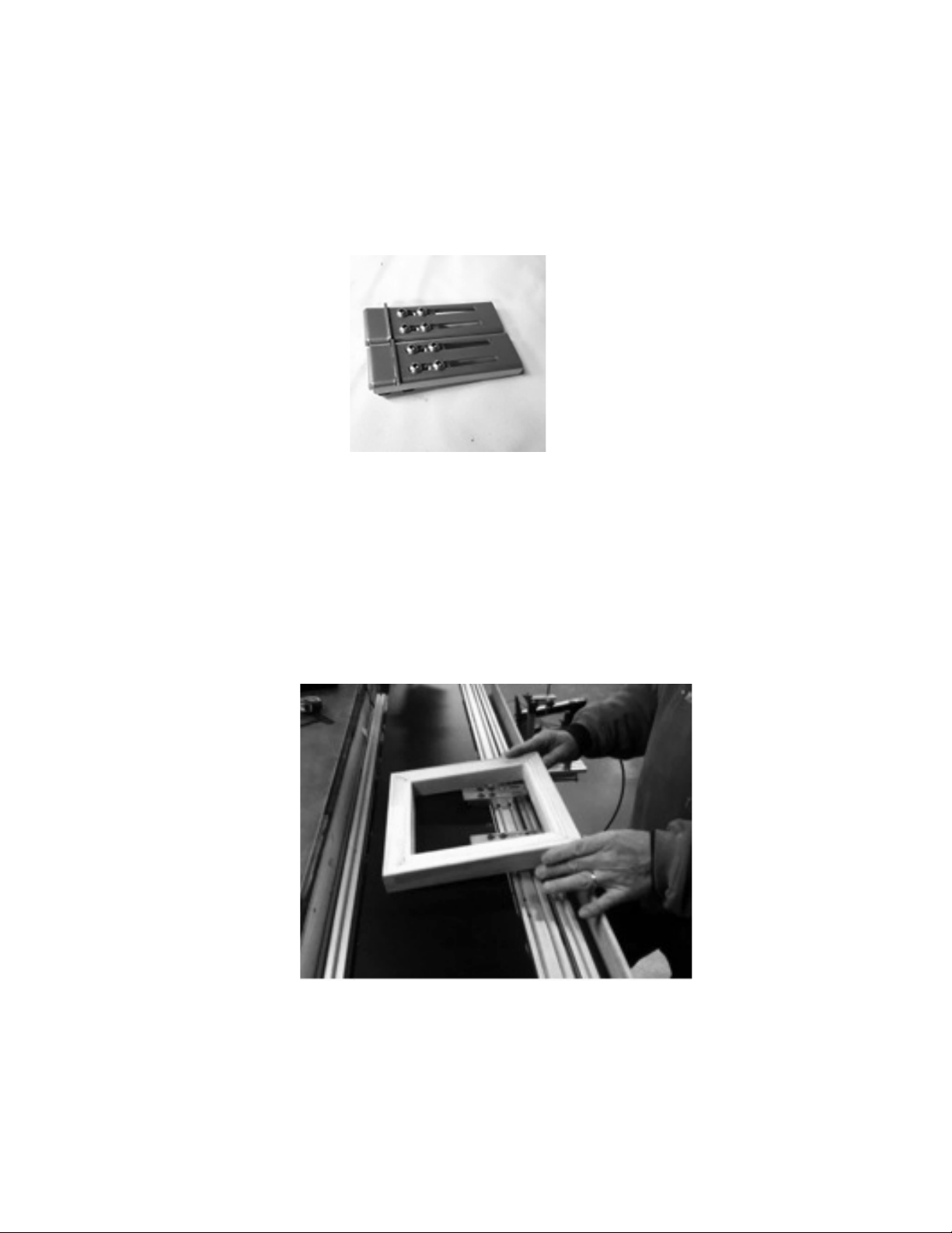
GALLERY STRETCHER-240 User manual

1
Instruction Manual
GS-60
Support Page: http://www.youtube.com/user/dweaverframe?feature=mhee
Introduction
The Canvas Stretching Machine is a fully pneumatic canvas stretcher capable of
stretching original art on canvas, giclee prints and any fabric suitable for stretching. The
following is a list of operating parameters that should be observed to ensure a safe and
efficient stretch:
1. Minimum amount of excess canvas 1.5” past the bottom of
stretcher bar and no more than 2.5”
2. Minimum stretcher bar width .75”
3. Maximum stretcher bar width 2.5”
4. Maximum supply air 120 psi
5. Minimum supply air pressure 90 psi (required for staple gun)
Safety Precautions
Air Pressure: before applying air to your machine, adjust the regulator at your
compressor to produce 90 psi. If you are using a pneumatic staple gun please be sure to
provide what the manufacturer recommends, this may require you to provide a 2 way
manifold from your compressor.
The Clamping Bar has a dedicated pressure regulator and it is set to a point that will not
exceed the Stretcher Bar pressure by more than 10 psi. This is to ensure that the canvas
is permitted to slip just enough to minimize overstretching. The operating pressure of the
Clamping Bar is internally preset to 50 psi….Do Not Adjust This Setting!
CAUTION:
the clamp and stretcher bar move slowly, they are deceptively powerful.
The force behind them can damage your fingers, please ensure that your hands and
fingers are clear of the clamp at all times. DO NOT place your fingers between the
Clamping Bar and Front Plate at anytime.

2
Orange
Yellow
STRETCH PEDAL
White
Black
CLAMP PEDAL
Grey
STAPLE GUN
Unpacking & Set-up
Inside The Box
(1) Two foot pedals (detent type) mounted on base plate
(1) Pair Stretcher Blocks
(1) Instruction manual
(1) Pair safety glasses
(2) T-wrenches
(1) Air hose to machine
Bench Mounting (Gusseted Brackets not included)
Your machine was designed to be mounted in front of a typical workbench this is the
most effective method. This is best accomplished with gusseted brackets that can be
purchased at any big box store. Snap a line at 3.25” from the top of the workbench and
install gusseted brackets on the line. It is recommended that a plywood façade be
installed on the face of the workbench to provide support for the bottom leg.
The GS-60 has hose fittings beneath the machine. You will need to allow access to these
fittings to avoid crimping the hose. The best way to do this is to use gusseted brackets
and nothing else. The hose should hang straight down and the machine rests on them.
(you may decide to use small “c” clamps to secure it from below)

3
Universal Mount Installation (Optional Equipment)
(Detailed Instructions & Video)
The universal bench mount consists of (1) pair of brackets for a 60” machine and (2) pair
of brackets for a 96” machine. The brackets are paired so that there is a left-hand and
right-hand bracket, (refer to photo at bottom of page) indicated by the small tab on each
bracket that favors one side as viewed from the front.
Installation for 60”:
Locate the centerline of the bench and make a mark. Place the left-hand bracket
(identified by the forward most tab on the left outside edge) where the outside edge of the
top mounting plate is 21.125″to the left of the centerline and secure it to the bench using
the 2 holes at top of the mount. There are (3) additional holes on the face of the mount if
you do not want to drill on top of your bench. Place the right hand bracket 21.125” to the
right of the centerline. Please confirm that the distance between the 2 small tabs in the
front are 39” apart inside to inside. These tabs will “trap” the machine to reduce
movement. Your mounts come with (2) metal ¼-20 screws that allow you to apply just a
little pressure. (pictured below)
Left bracket
tab outside
Right bracket
tab outside
42.25”
for 60”
Metal screws

4
Set machine on universal mount by placing the back rail of the machine into the 2 rear
slots. Tilt the machine as shown and lower the front onto the mount, the 2 front tabs of
the mount should rest on each side of the machines support rails as shown in the picture
below. This keeps the machine from moving left or right. The metal set screw on each
tab should only be tightened enough to make contact with the inside of the slot on the
machine’s frame.
Left bracket
tab outside
Tapped for
¼-20 metal set screw
(provided)

5
Foot Pedals & Mount
There are (2) foot pedals located on a steel plate. The pedal on the right controls the
“Clamping Bar”, the pedal on the left controls the “Stretching Bar”. Both foot pedals
are configured to allow air to flow when depressed. DO NOT have any part of your body
near the bars when in motion. Depressing the foot pedal once turns air on, depressing it
again turns off the air.
The clamping foot pedal engages the clamping bar to grip the canvas, the stretching pedal
controls the stretching bar. The stretching force is controlled on the right side of the
machine, the gauge on the deck indicates stretching force.
A color-coded tubing harness is attached to the foot pedal assembly. The loose ends must
be connected to the under-side of the machine (pictured below) to their corresponding
color-coded quick-connect fittings. The “Black” & “ White” are for the clamping pedal,
the “Orange” and “Yellow” are for the stretching pedal and the remaining “grey”
connector is for your staple gun. You should have a “white plug” inserted into that
connector to block off air until you are ready to connect a staple gun (optional
equipment). Simply depress the grey ring and pull out the plug.
A staple gun is not included with the GS-60.
There are (2) preinstalled T-nuts in the middle track that allow for a holster and a staple
gun. A holster is not included with the GS-60 but it is configured for one. Refer to
this section if you purchase one from us.

6
How to use Custom Stretcher Plates
The Custom Stretcher Plates, shown below, are included with your machine. The (4)
screws mounted on the stretcher bar allow the slotted brackets to slide in and out. The
slotted brackets allow for adjustment for different width stretcher bars.
Setting-up Stretcher Plates
Video: http://www.youtube.com/watch?v=94rntl0C0rY
Position both stretcher plates in the middle of the stretcher bar. Favoring one side may
cause the stretcher bar to bind so always stretch canvas from the center of the machine.
Place an assembled wood stretcher frame on top of the stretcher plates as shown below.

7
Position the frame so that it is against the “mechanical stops”, the short tab of metal about
1/8” high (these stops also facilitate alignment during the stretch). Loosen the (4) screws
on each of the slotted stretcher plates.
Apply air to your machine and verify that the clamping bar is open. Move the assembled
frame and the plates together in and out until the face of the wooden frame is
approximately ½” behind the angle bar. In other words, create a gap so the canvas will
“waterfall” down into the opening when the clamp is closed. This step (above and below)
is simulated without the canvas present.
Tighten all of the screws. This setting will not change for any stretcher bar that is this
width. This procedure would only need to be done again if you change to a different
width of stretcher bar.
This is referred to as the “Loaded Position”

8
LOADED AND UN-LOADED POSITIONS
Once the stretcher bars are adjusted and you are ready to stretch you need to remember
that all stretches start in the “un-loaded_ position. When the operator is ready to stretch
the canvas they would “clamp” the canvas and then move the wood stretcher frame
forward and off of the stretcher plates, it should now be resting on the angle bar in front
of the plates. This position is referred to as the “un-loaded” position. In this position the
stretcher bar should extend approximately ½” over the front of the angle bar. In summary
the wood stretcher bar should be on top of the stretcher plates but the approximately ½”
behind the face of the front angle bar in the “loaded” position. In the “un-loaded”
position the wood stretcher bar should be approximately ½” in front of the angle bar.
This is referred to as the “Un-loaded Position”
Basic Operation
Video: http://www.youtube.com/watch?v=w5000LVd9tc
1. Lay the artwork “facedown” on a clean work surface behind the machine just of
the deck. Fold the canvas along the image so that approximately 1/16” of the
image is extending over the radius.

9
2. Turn the artwork 90 degrees and make a second fold along the image.
3. Place the assembled stretcher frame (flat side up) on the artwork and slide it
against the first crease. Then slide the outside rail against the second crease. This
is the fastest way to align your artwork.

10
4. Once the artwork is aligned create the “starter course” using a pneumatic staple
gun. Be sure that the artwork stays parallel to your edge. Adjust air pressure of
staple gun so that the staples due not penetrate the canvas.
5. Place the stretcher frame on top of the stretcher plates with the starter course away
from the operator. This is called the “loaded position”.
Note the position of the stretcher bar against the “mechanical stops”.

11
6. From the front of the machine there should be enough of a gap between the angle
bar and the clamping bar so that the canvas will “waterfall down” into the opening.
The operator should not have to feed the canvas in by hand in most cases.
7. Be sure to position stretcher plates closer to the center of the artwork. Moving
them toward the outside rails will result in an uneven stretch; a few inches left and
right of center. Art larger than 30” may require moving the plates farther apart,
but try to avoid moving the plates toward the outside rails. The outside of the
stretcher frame already has strength from the (2) outside rails; fortify the center
where it is needed.
8. Feed the loose end of the canvas into the gap and step on the “clamping pedal”
once to engage the clamp. There should be at least 1.5” of excess canvas beyond
the bottom of the stretcher bar to allow the clamp to get a good hold.

12
9. Once the canvas is clamped and you are satisfied with the alignment move the
entire assembly forward and off of the plates. This is referred to as the “un-loaded”
position. The stretcher frame should be in front of the plates and the canvas should be
held fast beneath the clamp. It is now ready to be stretched.
10. Depress the left foot pedal (stretching pedal). Be sure to maintain control of the
stretcher frame with your free hand. It should rest on the outside rail applying only
light pressure. The stretching pressure should be no more than 15-20 psi to start a
stretch. Increase the pressure slowly using the regulator on the right side of the
machine and let the frame rise no more than 3-4”. Do not push the frame flat against
the deck. Pushing down on the frame during a stretch will promote slipping.
“Small art tends to flip off the stretcher plates. Always keep a free hand on the rail.”
Note overhang

13
11. The pressure gauge on the right side of your stretching machine indicates
regulated air pressure to the “stretching plates”. It is a safe practice to always
start a stretch at around 15 – 20 psi this is accomplished with the
Stretcher Bar Regulator.
12. If you need more pressure you can always increase stretching pressure. Do not
“overstretch”, a tight stretch can be obtained with only 20-30 psi provide you
have a stretcher bar with a nice radius. Stretcher bars should always have a
pronounced radius, the harder the edge the harder it is to get the canvas to
stretch.
13. When you are satisfied with the tension you can staple the canvas to the frame
with a long-nosed pneumatic staple gun. The staple gun is operated upside down
and the trigger is depressed with the thumb. Slide the nose of the staple gun
along the angle bar beneath the stretcher frame. Place a staple at least 1 every
inch.
14. Release the stretch by stepping on the stretching pedal. Depress the clamping
foot pedal again to open the clamp and remove the artwork. Rotate the artwork
90 degrees; use the deck of your machine and the work surface to support the
artwork. This is how you stretch each end.
15. You are now faced with the decision to fold the corners and continue stretching
or cutout the excess canvas and then stretch. Removing the excess canvas is the
recommended method and provides the best results.

14
Cutting Excess Canvas
1. After the first stretch, remove the artwork and lay it facedown on your work
surface as shown. Create a slight crease on the corner to define the edge.
2. Cut just inside the creased line and stop at the stretcher bar.
3. Make your second cut along the stretcher bar as shown in the photo below.

15
4. Rotate the artwork 180 degrees and repeat the process. Place the artwork back on
the stretcher plates in the “loaded position” and continue with the remaining
stretches.
Troubleshooting
Every machine leaves our facility fully assembled and tested, however, during transit it is
possible that the contents may have experienced some “sudden changes in motion”, this
can lead to misalignment issues and even breakage. This section will attempt to resolve
some of the possible issues you may encounter with your machine.
Clamping Bar Not Closing
The Foot Pedal operates like a light switch; in this case it is air and not electricity. If your
foot pedal does not close please ensure that you have at least 90 psi from the compressor
and that it is going into the machine at the “green” quick-connect fitting.
Air is going to the machine but it is still not closing? Call us at 614-861-4582
Stretcher Bar is Hanging Up
In nearly every case this is caused during transit, the cylinders and their mounts are
“forced” out of alignment. This is best resolved over the phone.
If you are experiencing this problem please do not hesitate to contact us at 614-499-4989
and ask for Dave.
The Canvas is slipping during a stretch
The Clamping Bar is preset to 50 psi, located beneath the deck; this regulator should not
be tampered with unless you have been instructed by us to do so. Changing this setting
may cause severe damage to the Clamping Bar and will void your warranty. Do not
change this setting. Most stretches are done at no more than 30 psi; this will produce a
nice tight stretch with giclee canvas. Heavy canvas and oversized art may require more
pressure, but it should not exceed 50 psi. That is why we have preset the clamp to 50 psi
this will allow for a certain degree of “slip”. If the clamp is preset to 50 psi and the
stretching pressure exceeds 50 psi, then there will be slipping.
Stretcher Bar is lifting when stretching
This is by design. Smaller artwork will tend to rise very easily and large artwork may not
rise at all, but that is fine. Typically, the artwork will rise about 3-4”, as shown in the
photo below. The operator should not “push down” on the artwork in an effort to keep

16
the artwork flat. Pushing down will tend to force the canvas out of the grasp of the
clamping bar; this would be equivalent to increasing the stretching pressure past 50 psi.
Under normal operating conditions the Stretching Bar will rise a little above the top of
the Clamping Bar as the stretching pressure is increased. The closer the stretching
pressure is to the set point of the clamping bar the more likely it is to rise.
This is not an issue unless the bar remains in this position or there is excessive play. If
this occurs contact us.
Clamping Bar is lifting during stretch
Under normal operating conditions the Clamping Bar will tend to rise a little above the
top of the angle bar as the stretching pressure is increased. When the canvas is clamped
and being stretched there is a strong upward force that tends to pull the clamping bar
upward with the canvas. This is not an issue unless the bar remains in this position or
there is excessive play. If this occurs contact us.
Stretching Bar deflecting, or deflecting unevenly
This is also a normal response during a stretch. This Stretching Bar was purposely
chosen because of the amount of deflection it has, this conforms well to the rubber
extrusion. As for the uneven bar, this is more a matter of placement of the artwork. Try
position the artwork at the center of the machine and work from there, favoring one side
will result in an uneven travel but should not affect the quality of the stretch.
Canvas is not tight
How tight is tight? There have been many arguments regarding what is considered a
tight stretch. Canvas is very dynamic and is susceptible to atmospheric conditions, what
once was tight will soon be loose. Over-stretching a canvas will give the canvas memory

17
and is not likely to return to it’s original condition. Our belief is that stretching light
giclees at 15-20 psi is more than sufficient and that heavy canvas should be no more than
30-40 psi.
Stretching Large Art
Artwork larger than 30” x 30” should probably be made with a cross-brace; this will
reduce the amount of deflection of the stretcher bar during a stretch. There is a “keystone
effect” that occurs when stretching large pieces when the plates are placed close to the
outside rails. The rails provide strength for the stretcher frame, placing the stretcher
plates away from the center causes the stretching force to be applied more to the outside
and not in the middle were it is needed. The ideal placement of the stretcher plates is half
the distance between the center and the outside rail, do this for both sides.
Tips & Tricks
Large artwork will not typically rise very much during a stretch due to the weight of the
stretcher bar. The heavier the stretcher bar the less likely it is to rise. Most operators
would tend to increase the stretching pressure above 50 psi; this will cause the canvas to
slip out of the grip of the clamp. Instead, the operator should lift the far end of the
artwork until it is approximately 3-4” above the work surface, this will permit the canvas
to stretch over the edge of the stretcher bar with less resistance. Placing a soft foam roller
or pad of cardboard under very large artwork will produce the desired effect.
Here is a link to our support page where you will find several videos that may help with
the set-up, making folds, operations and general answers.
http://www.youtube.com/user/dweaverframe?feature=mhee
This manual suits for next models
1
Table of contents