2 PAGE
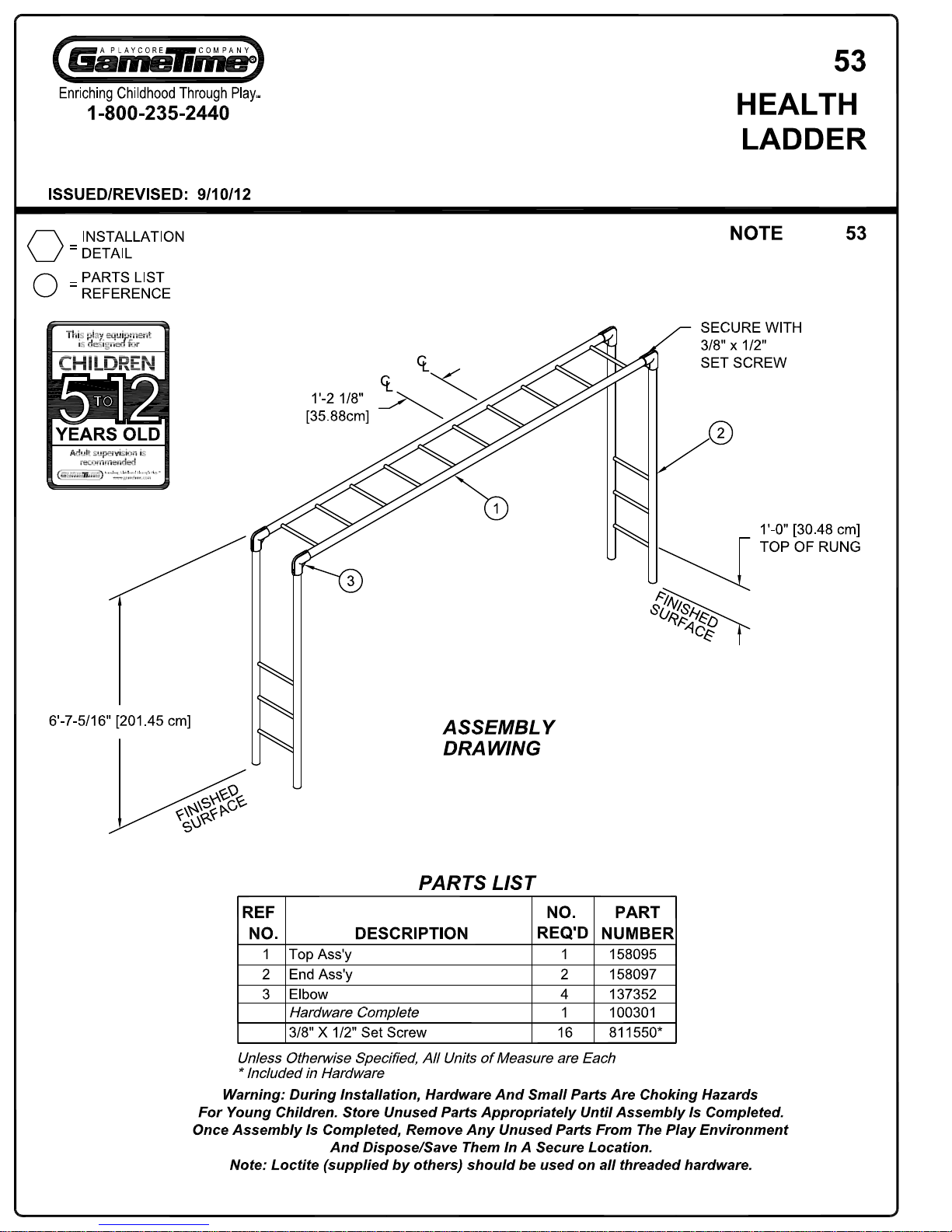
PARTS LIST
PART NUMBER
QTYDESCRIPTION
ITEM
147862
4
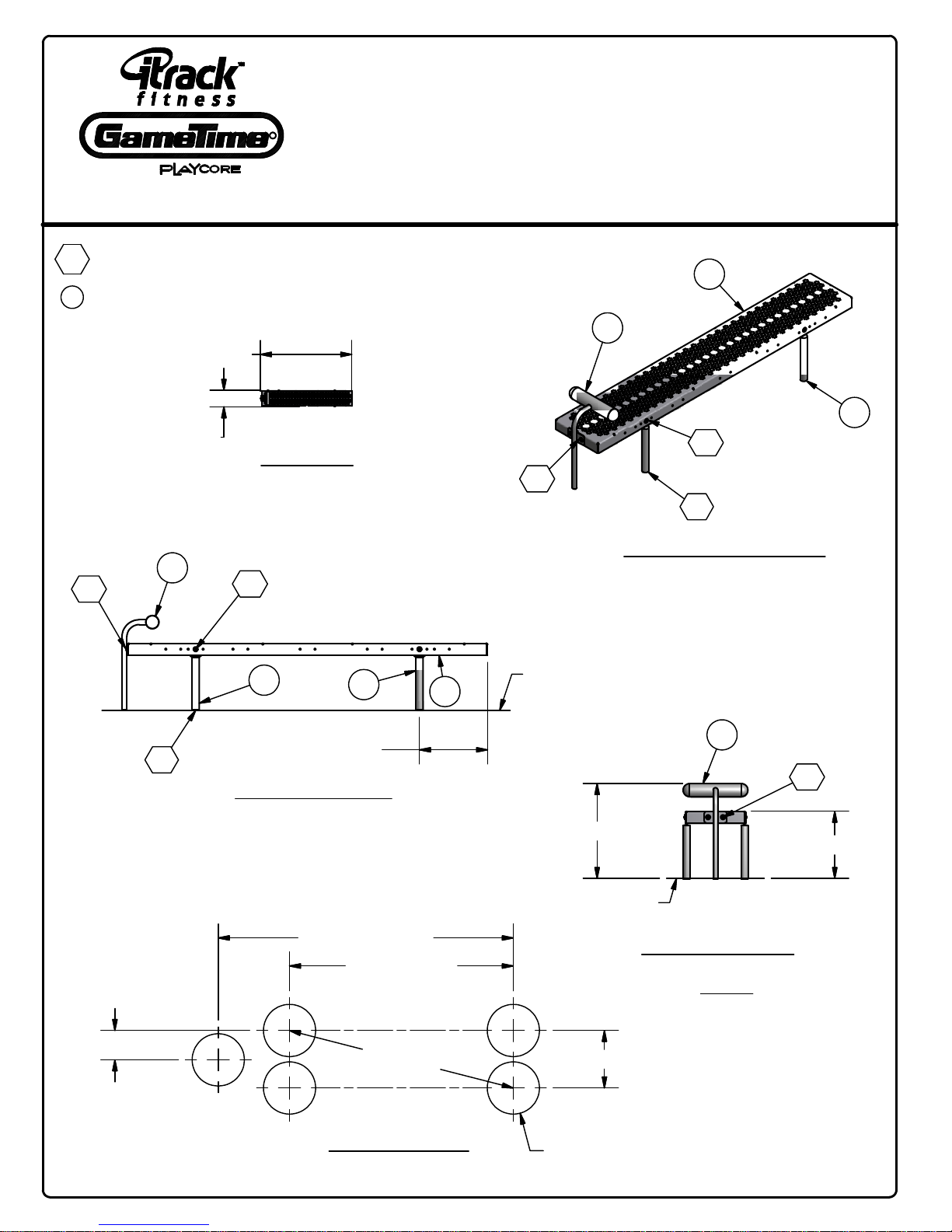
BENCH LEG (3'-11 1/2" [120.65cm])1
1601881
PUNCHED STEEL BENCH ASS'Y
2
1760891FOOTRAIL ASS'Y3
202095**
1
SIT-UP STATION SIGN
4
2120941
HARDWARE COMPLETE
135038*
4
1/2" ANCHOR ROD (1'-0" [30.48cm])
811051*
6
3/8" x 1 1/4" B.H.C.S.
817424*
8
3/8" FLAT WASHER (1 1/4" O.D.)
817334*
6
3/8" LOCKWASHER
804053*63/8" HEX NUT
INSTALLATION INSTRUCTIONS
1.) Before starting assembly, review the General
Installation Instructions at the beginning of this Installation
Guide and the Typical Assembly Details in the back.
2.) Determine proper location for Sit-Up Station.
Refer to Equipment Layout Plan provided and any
applicable project site drawings.
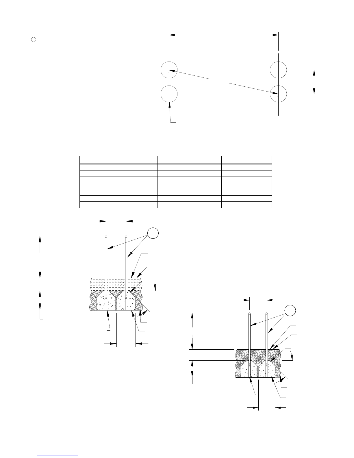
3.) Dig footings for bench supports. Maintain footing
spacing, size and depth as indicated on the ground plan.
Refer to Detail 321. Allow for depth of desired Finished
Surface.
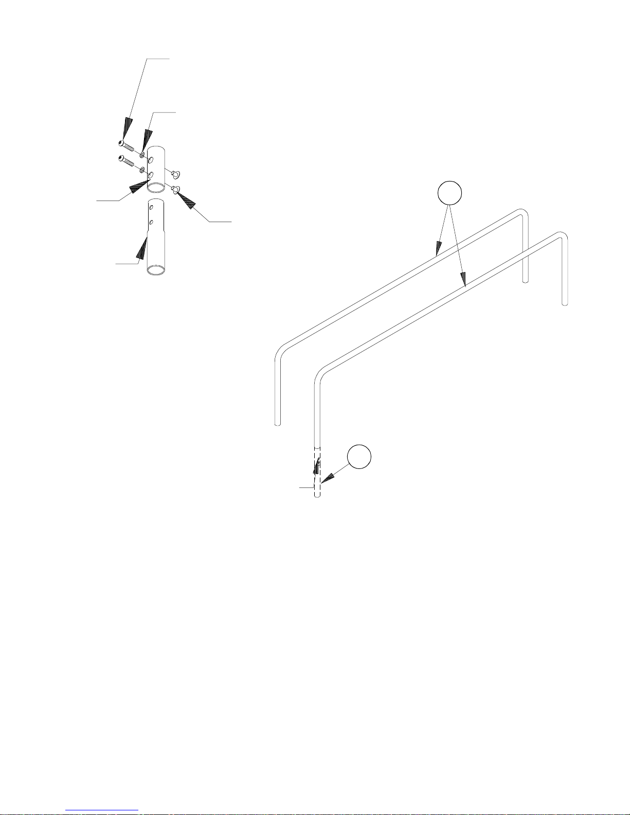
4.) Attach four legs to the bench. Refer to Detail E04.
5.) Attach footrail assembly to bench. See Detail E05.
6.) Position assembled bench in footings; align, plumb,
and brace bench in place. Pour concrete as shown on
Detail 321. Be sure to hold top of concrete footing 0'-6"
[15.24cm] down from the Finished Surface. Slope top of
concrete for proper drainage.
7.) Refer to Sign Frame Installation Sheet for instructions
on Sign mounting.
8.) Allow concrete a minimum of 48 hours to cure and
harden before using bench.
SPECIFICATIONS
BENCH LEG: Shall be made of 1-7/8" O.D. galvanized
pipe.
BENCH ASSEMBLY: Shall be fabricated of punched
steel metal with a plastisol coating.
FOOTRAIL ASSEMBLY: Shall be an all-welded
construction fabricated of 3-1/2" O.D. (13 gauge)
galvanized pipe, 1-5/16" O.D. galvanized pipe, 3/16" x 3"
H.R. flat steel, and galvanized pipe cap. Final assembly
shall also include cast aluminum caps and self-sealing
pop rivets.
FINISH: The Bench Legs, Footrail Assembly and
Handrail Assembly shall all have a powder coat finish.
HARDWARE: All nuts, bolts, screws, inserts, and
lockwashers used in the assembly of all play equipment,
shall be stainless steel, yellow dichromate plated steel,
blue-coat plated steel, mechanically galvanized or powder
coated/yellow dichromate plated steel. All primary
fasteners shall be 300 series stainless steel. Fasteners
with yellow dichromate treatment have an electro
deposited, 99.9% pure zinc substrate applied from a
specially formulated solution sealed with a yellow
dichromate top coat designed to work in conjunction with
the zinc plating. Yellow dichromate has a 320% longer
life to white corrosion and 275% longer to red corrosion
than does hot-dip galvanizing.
SPECIFICATIONS: GAMETIME® has a policy of
continuous improvement and reserves the right to
discontinue or change specifications without notice.
* Included in Hardware
Warning: During Installation, Hardware And Small Parts Are Choking Hazards
For Young Children. Store Unused Parts Appropriately Until Assembly Is Completed.
Once Assembly Is Completed, Remove Any Unused Parts From The Play Environment
And Dispose/Save Them In A Secure Location.
Unless Otherwise Specified, All Units of Measure are Each
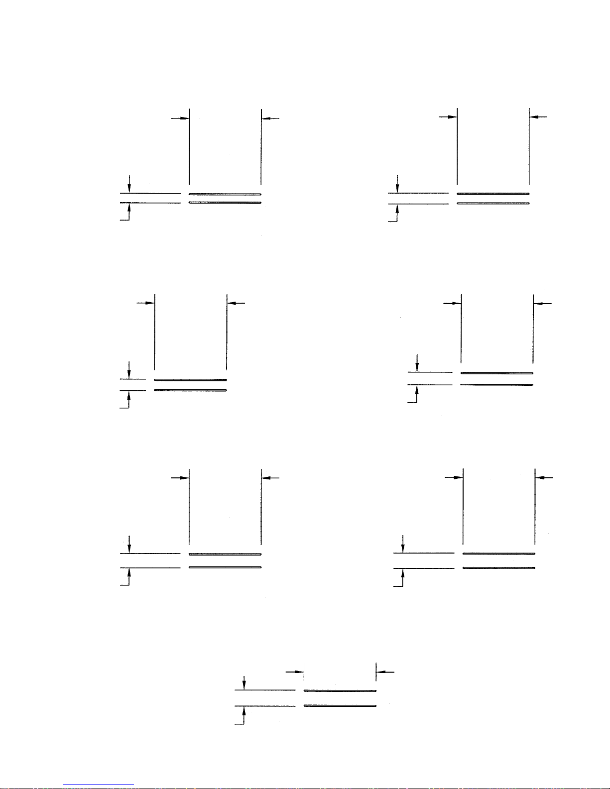
Note: Peen Tee-Nuts and Flatwashers to match radius of pipe after assembly is complete.
**Sign Frame with Hardware Sold Separately