manuals.online logo
Brands
  1. Home
  2. •
  3. Brands
  4. •
  5. Gardner Bender
  6. •
  7. Construction Equipment
  8. •
  9. Gardner Bender Eegor B400 Series User manual

Gardner Bender Eegor B400 Series User manual

1
Gardner
Bender
Instruction
Sheet
Model B400, B400D,
B400L & B400DL
Eegor
®
Hydraulic Benders
IMPORTANT RECEIVING INSTRUCTIONS: Visually inspect all components for shipping damage. If any
shipping damage is found, notify carrier at once. Shipping damage is NOT covered by warranty. The carrier is
responsible for all repair or replacement costs resulting from damage in shipment.
Frame Plate
Bending Shoe
Follower Bar
Cylinder
U-strap
Double Anchor Pin
Coupler
Cylinder Support Block
Compression Roller Assembly
(Roller Ass'y/Cylinder Clevis/
Roller Ass'y)
U-strap
Lock Pin
4" dia. Roller
Shoe Pivot Pin
Note:
Position couplers in direction
shown so as to prevent damage
to hoses when making full
90˚ bend.
Eegor® & Ultra EegorTM Bender Component Chart
GARDNER BENDER CANNOT BE HELD RESPONSIBLE FOR DAMAGE OR INJURY CAUSED BY
UNSAFE USE, MAINTENANCE OR APPLICATION OF ITS PRODUCTS. Please contact Gardner
Bender’s technical service department for assistance if you are in doubt as to the proper safety
precautions essential to designing and setting up your particular application.
Eegor® Benders are shipped in metal
storage cases.
P408S Electric Hydraulic Pump
BS3500 31⁄2"
BZ728
BS3000 3"
BS4000 4"
BFB4000 4"
BFB3500 31⁄2"
HC-913
BFB3000 3"
BZ34 3"
BZ76
BZ28 21⁄2"
BZ39 31⁄2"
BFB2500 21⁄2"
BS2500 21⁄2"
BZ44 4"
CD3014
B400
Order Eegor® Set Model Number Size Set Pump and Hoses
Bender
Frame
Adjustable
Compression
Roller
Assembly Pins Cylinder
Bending
Shoes
Follow
Bar U-strap
Deluxe Eegor®
ULTRA Eegor™
B400LP408S 2-1/2",
3",
3-1/2",
4" sets
P408S Pump
(2) HC913 Hoses BZ70
includes
cylinder
block, top
and bottom
frame
plates and
frame pivot
assembly
with clevis
eye
BZ72
includes
all rollers,
top roller
plate
assembly,
and bottom
plate
assembly
BZ74
double
anchor
frame
pin
BZ76
U-strap
pin
BZ78
bend
shoe
pin
CD3028
BS4000
BS3500
BS3000
BS2500
BFB4000
BFB3500
BFB3000
BFB2500
BZ44 (4")
BZ39 (3-1/2")
BZ34 (3")
BZ28 (2-1/2")
Standard Eegor®
Bender Set
B400DLP408S
2-1/2",
3", 4"
sets
P408S Pump
(2) HC913 Hoses
BS4000
BS3000
BS2500
BFB4000
BFB3000
BFB2500
BZ44 (4")
BZ34 (3")
BZ28 (2-1/2")
Standard Eegor®
ULTRA Eegor™
B400DL Pump and Hose
Not Included
Standard Eegor®
ULTRA Eegor™
Bender Set
B400DLP408S P408S Pump
(2) HC913 Hoses
2
Unpacking
Remove all bender shoes, follow bars, U-straps and
pins. Inspect for damage and compare these
components to the complete set shown on page one
for possible missing parts. Depending on which set
you purchased - the basic difference in component
content will be whether you purchased a set having
the 31⁄2" size shoe, follow bar and U-strap included.
Maintenance of your Eegor® Bender
Aside from conventional care of the hydraulic
components, very little maintenance of the Eegor®
bender is required. Removing sand or dirt from
grooves and moving parts will extend bender life and
facilitate ease of operation.
Lubricate rollers, when needed, with molybdenum
disulfide paste only (such as Dow Corning’s
Molykote #G-n paste, or equivalent). For heavy
use, lubricate rollers weekly. Note: Graphite
formulations are not equivalent lubrication.
Bender Frame Assembly -
Removal, Transporting & Storage
To remove or carry the bender frame assembly—do
so by placing hand on the bottom frame plate. You
should have assistance so that the lifting points are
at the front end and back end of the bottom plate.
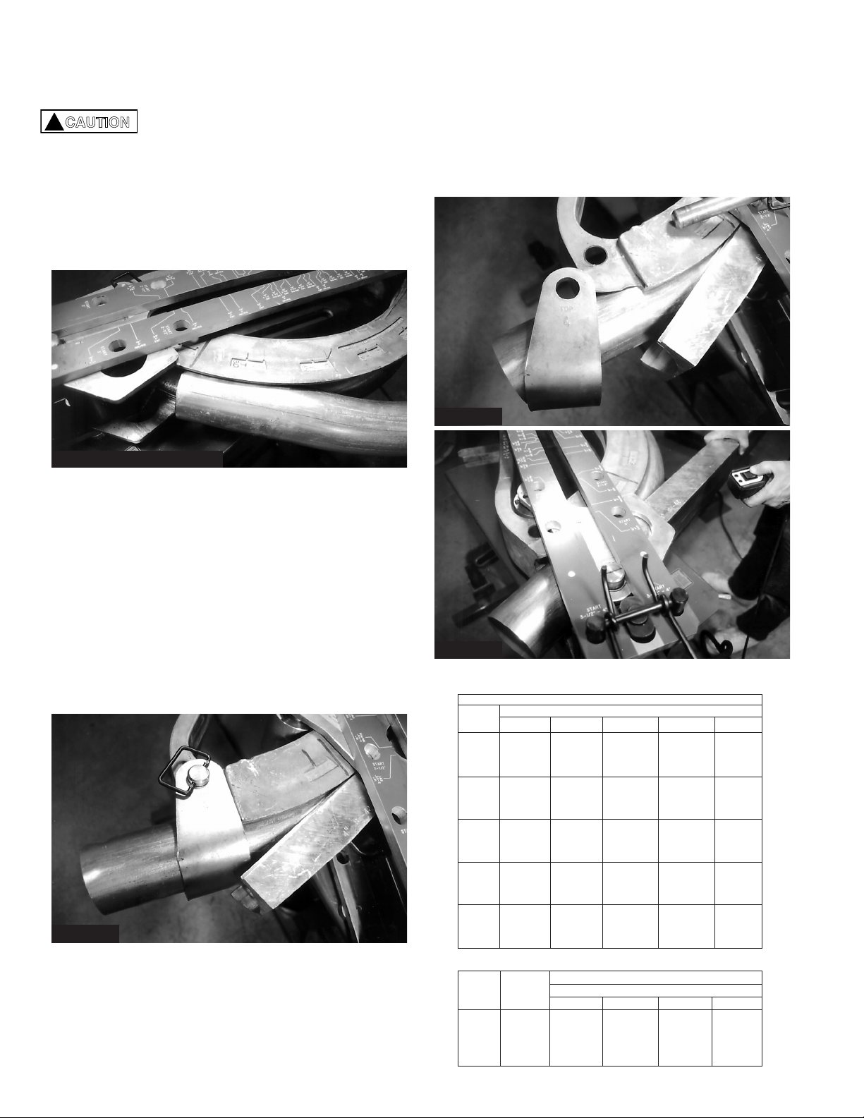
Avoid pinched fingers by keeping
hands away from the BZ72 roller assembly, which
pivots freely on a pin through the cylinder rod eye and
may swing suddenly aside during handling.
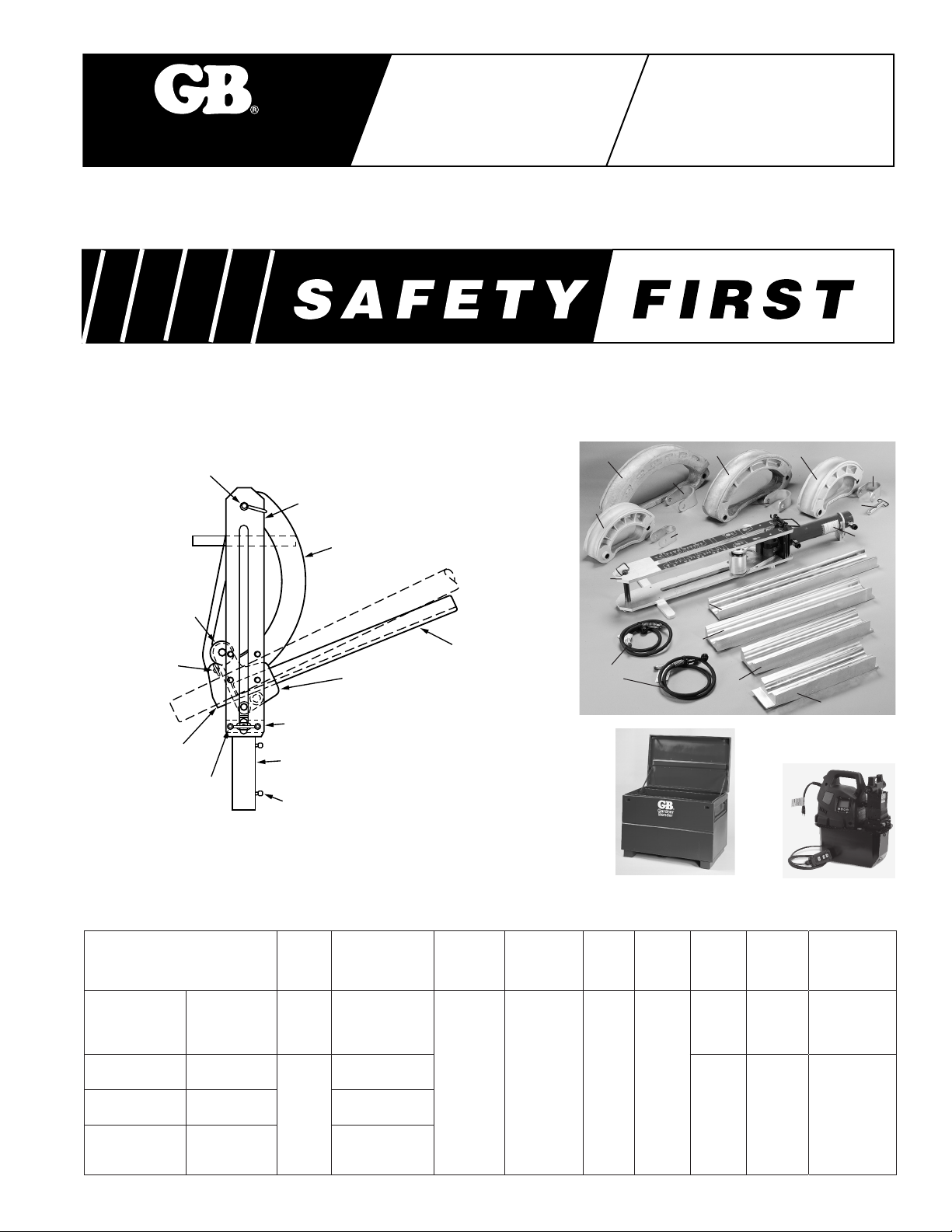
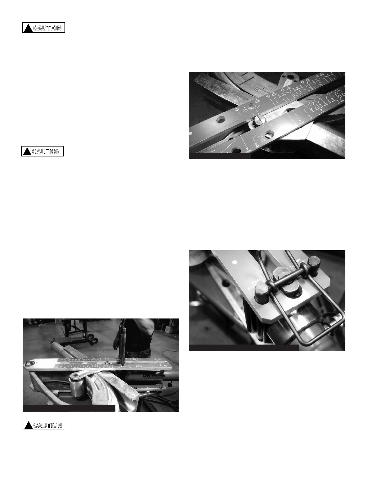
The hydraulic cylinder, cylinder mounting block and
compression roller assembly slide back and forth
between the two frame plates.
This sliding action is a function of the bender design
for locating the cylinder to meet the need of your
particular conduit size; up to a full 90˚ without the need
of another set-up or reposition of the conduit.
The slide action permits the bender assembly to be
collapsed to a shorter length for handling and storage.
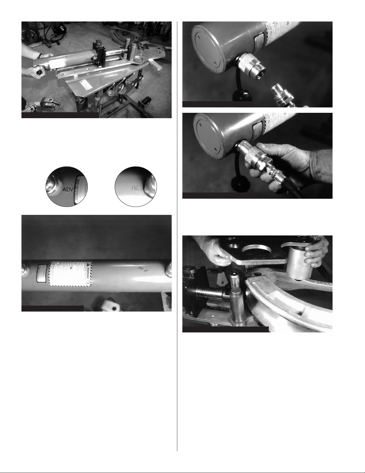
When storing, be sure to remove the hydraulic hoses
from the cylinder and install dust caps on the coupler
ports. See the back page for details of storing the
B400DL and B400L models.
Safety Alert Symbol
The symbol above is used in conjunction with a
danger, warning or caution statement. It alerts
operators, supervisors and all personnel that safety
precautions are required during specific operations
and specific conditions. Failure to comply with safety
data could result in serious injury or death.
Indicates a high probability of death or severe injury or
major property damage could result.
Indicates serious but less probability of death, sever
bodily injury or major property damage could result.
A less serious alert, but still demands attention to
detail. It indicates a hazardous condition that may
cause minor injuries or property damage.
Introduction
Gardner Bender™ produces twelve versions of the
Eegor® hydraulic conduit bender. Each version uses a
hydraulic cylinder and electrically operated pump to
produce the force necessary to bend conduit sizes
21⁄2" to 4". Differences between model numbers are
based on the accessories included with each model
and the length of the cylinder used to bend the
conduit. Since the process of bending is the same for
all models, the instructions and safety precautions
apply to all application and uses of Gardner Bender™
hydraulic conduit benders.
Bending conduit encounters a wide range of situations
and a variety of conduit materials. Because of the
multiple job specifications, it is not possible to provide
instructions covering every situation. Principal bending
formulas apply to use of the model B400 series
benders. Assembly instructions are specific. Follow
them precisely to ensure safe, reliable and effective
conduit bending.
All instructions are important, but safety alert
symbols are located throughout this manual, and a
separate section is included to address specific
safety concepts.
Before operating Gardner Bender™ conduit benders,
read and understand this entire manual. If any
subjects are not understood, contact Gardner Bender
at 414-352-4160; ask for technical services.
!CAUTION
!
!
!
!WARNING
!DANGER
!CAUTION
3
The Eegor® bender develops 30 tons of force at 9,250
psi. Greater forces will be generated between the
rollers, follow bars and bending shoe. Operators must
follow instructions for assembly and bending conduit
to avoid pinch points and applying forces to incorrect
bender components.
Do not use damaged parts to assemble the
Eegor® bender. Items that are damaged or broken
due to extensive wear must be replaced to avoid
potential hazards to the operator.
Keep hands and loose clothing away from all moving
parts. Frames and rollers move under high pressure.
Do not place hands on conduit or between conduit
and follow bar during operation. Severe injuries could
result.
Do not connect or disconnect hydraulic hose fittings
with pressure in the system. A rigid hose indicates the
presence of internal pressure. Prior to electrical or
hydraulic repairs, retract the hydraulic cylinder and
turn off the hydraulic pump.
!CAUTION
!CAUTION
!WARNING
!CAUTION
IMPORTANT—USER SAFETY AND PROTECTION: In setting up systems, take care to select the proper
components and design to ensure appropriate integration with your existing operations and equipment. Observe all
safety measures to avoid the risk of personal injury and damage to property and equipment through improper usage.
Bender Assembly
A. Frame Assembly
1. Remove the frame assembly and hydraulic
cylinder from the metal case. Place the assembly
on a flat surface. Figure 1.
The cylinder slides within the frame
assembly. When lifting or moving,
keep the frames as level as possible
to prevent injury from moving parts.
!CAUTION
Figure 1: Frame Assembly
Figure 2: Lock-on Frame
2. A pivoting lock holds the top frame in place.
Figure 2.
3. Turn the pivot lock to align it with the slot in the
frame. Lift the top frame off the roller assembly.
Figure 3.
Figure 3: Removing Top Frame
4. Place your foot on the lower frame, grasp the end
of the hydraulic cylinder and pull it toward you.
Align the slots of the cylinder mounting block with
holes in the lower frame that correspond with
conduit size being bent. Figure 4.
NOTE: For model B400L and B400DL align the
cylinder block with the holes for 31⁄2" & 4"
conduit size (last holes in frame). The
cylinder will remain in this position for all
bending sizes and angles to 90˚.
4
7. Remove the upper roller and plate assembly by
pulling straight up. The upper plate and large
aluminum roller are a single assembly. Figure 7.
Figure 5: Hose Installation
Figure 6A: Installing Couplers
Figure 7: Upper Roller Plate Removal
Figure 6B: Installing Couplers
Figure 4: Moving Cylinder Frame
5. Install the two hydraulic hoses. Apply one wrap of
teflon tape to the threads on the end of the hose.
Remove the pipe plugs from the pump valve, one
port is marked “ADV” the other is marked “RET”.
Install a hose in each port. Figure 5.
6. Connect the hose from the “ADV” port to the
hydraulic cylinder coupler located near the base
of the cylinder. Make sure there is no dirt or
debris in either half prior to assembly. Push the
hose coupler firmly into the cylinder coupler, then
tighten coupler collar. Connect the hose from the
“RET” port to the remaining cylinder coupler.
Figure 6A & 6B.
IMPORTANT: The hose coupler must be firmly
seated in the cylinder coupler and held
tightly while turning the coupler collar.
Hand tighten the collar. Do not use
tools to tighten. Failure to properly
assemble couplers will inhibit oil flow.
8. The lower plate and roller assembly remain
in position during normal shoe and follow
bar installation.
Bending Shoe and
Follow Bar Installation
A. Model B400L and Model B400DL Ultra Eegor™
1. The B400L and B400DL use a 28" hydraulic
cylinder. As a result, the upper and lower plate
assemblies use the 31⁄2"–4" frame holes for
mounting all sizes of conduit bending shoes. See
figure 8. For smaller sizes of conduit, the cylinder
plunger must be advanced to position the roller
assembly against the follow bar.
5
2. Position the desired size shoe on top of the lower
roller and plate assembly. Be sure the bend angle
numbers are facing up. Figure 9.
Figure 8: Locating B400L Hydraulic Cylinder
Figure 9: Positioning Bend Shoes on B400L
3. The top plate and roller assembly is installed over
the shoe. Prior to installation, move the indicator
knob to the “C” position for rigid or IMC conduit;
the “T” position for EMT (thinwall). Figure 10.
4. The large roller axle has two flats which engage
the retaining collar on the lower plate. Press the
upper plate down until the lower roller axles are
flush with the top plate holes and the flats of
the upper roller shaft are firmly seated in the
retaining collar.
Figure 10: Position Indicator Knob to “C” or “T”
Figure 11: Top Plate Installation
NOTE: The roller assembly axle may not engage the
collar initially. To ensure proper engagement,
move the indicator knob slightly until the axle
seats properly. Figure 12.
Figure 12: Correct Upper Plate Position
Figure 13: Hole Alignment Pivot Pin BZ78
5. Move the bend shoe to align the pivot hole with
the hole in the bottom frame. If the shoe is too far
away, start the hydraulic pump. Advance the
cylinder until the pivot hole is located under the
frame hole. Install the pivot pin (BZ78). Figure 13.
6. Install the “U” strap. Be sure the U-strap size
matches the bend shoe size. The stamped
numbers must face up. Position the “U” strap and
secure with pin BZ76. Figure 14.
6
B. Model B400 and B400D
1. The B400 and B400D use a hydraulic cylinder with
a 14" stroke. As a result, the cylinder mounting
block must be moved to the holes in the frame that
match the size conduit being bent. Figure 15.
Figure 14: Installing “U” Strap & Pin
Figure 15: Model B400 & B400D Cylinder Block Locations
Figure 17: Position of Indicator Knob
Figure 18: Top Plate Installation
Figure 19: Bend Shoe Pivot Hole
Figure 16: Installing Bend Shoe
2. Slide the cylinder along the bottom frame until the
cylinder mounting block grooves are aligned with
the desired holes in the lower frame.
3. Position the bend shoe on top of the lower roller
plate. Be sure the bend angle numbers are
facing up. Figure 16.
4. The top plate and roller assembly are installed
over the bend shoe. Prior to installation, be sure
to move the indicator knob to either “C” for Rigid/
IMC or “T” for EMT (thinwall) conduit. Figure 17.
5. The axle for the large roller (upper plate
assembly) has two flats which engage the retainer
of the lower plate assembly. Press the upper roller
down until the lower roller axles are flush with the
top plate. The flats on the upper roller axle must
fully seat into the retainer collar. Figure 18.
NOTE: The roller assembly may not fully seat on the
first attempt. To ensure proper engagement,
move the indicator knob (slightly) until the
axles of the lower rollers are through the top
plate and flush with the top of it.
6. Move the bend shoe to align the pivot hole with
the hole at the end of the lower frame. Figure 19.
bend shoe. Install the retaining pin (BZ78) through
the upper frame, bend shoe, and lower frame.
Secure with hairpin cotter. Figure 20.
7
Figure 20: Install Frame & Pin
Figure 21: “U” Strap & Pin Installed
Bending Conduit
A. B400 and B400D
1. The cylinder mounting block has a groove along
each side to accept the double anchor pin. Move
the hydraulic cylinder until the grooves in the
mounting block are aligned with holes in the
frame. The numbers next to the holes must agree
with the conduit size being bent. Figure 22.
Figure 22: Start Holes for Conduit Sizes
2. Install the double anchor pin (BZ74) by inserting it
in the holes of the upper frame, through the block
grooves and through the holes of the lower frame.
Figure 23.
8. Turn locking pivot on cylinder block until it is
positioned across the slot in the frame.
9. Place the “U” strap on the end of the bend shoe.
Be sure the number, stamped in the strap, is
facing up. Secure with “U” strap pin BZ76.
Figure 21.
The “U” strap pin (BZ76) must be
through the top hole, bend shoe and
bottom hole of “U” strap. If the bottom
hole is not engaged, the “U” strap will
be damaged during bending.
Figure 23: Double Anchor Pin Installation
!CAUTION
Figure 24: Installing Conduit in Shoe & “U” Strap
3. Slide conduit into the shoe groove and through the
“U” strap. At least 2-3 inches of conduit must
extend beyond the “U” strap to avoid deforming
the end of the conduit. Figure 24.
4. Insert the correct follow bar, tapered end first,
between the rollers and conduit. The follow bar
must be firmly seated against the “U” strap. A
follow bar is used for all types of conduit.
Figure 25.
7. Position the upper frame over the shoe assembly.
Align the single pivot hole with the pivot hole in the
Figure 25: Follow Bar Installed
8
!CAUTION
Figure 26: Final Bend Angle Procedure
!CAUTION
To prevent damage to the follow bar,
be sure the follow bar is inserted
tapered end first and rests against
the “U” strap. When installing the follow
bar, the numbers engraved into the
bar must face up.
5. If the follow bar will not fit between the roller
assembly and the conduit, the rollers will have to
be moved. Turn the pump on. Press the “Retract”
button momentarily to move the rollers back.Turn
pump off. Push follow bar into position against the
“U” strap.
6. Prior to pressing the advance button, hold the end
of the follow bar in place by pushing it forward.
Do not place fingers between follow
bar and conduit. Severe injury
will result.
7. Press “Advance” button to begin bending. Once
follow bar engages all rollers and bend begins, let
go of the follow bar. Continue holding the
“Advance” button until the bend is complete or the
cylinder reaches maximum length.
8. Large 3", 31⁄2", and 4" conduit require two cycles
of the hydraulic cylinder. When the first stage is
complete the cylinder will stop and the pump
motor will begin to stall. Release the “Advance”
button. Press return (momentarily) to release
pressure on the anchor pin. Do not remove the
conduit shoe or follow bar from the bender.
9. Lift and remove the anchor pin. Press “Retract”
button until cylinder mounting block grooves are
aligned with holes marked 21⁄2". Replace the
anchor pin through the top frame, cylinder block
and lower frame. Figure 26.
Figure 27: Angle Indicator
!CAUTION
Reading Bend Angles
1. Bend angles are printed on the upper frame decal.
Locations exist for Rigid, IMC and EMT conduit.
Locate the mark indicating the type of conduit and
the angle desired. Figure 27.
To avoid damaging the anchor pin, be
sure both pin shafts protrude through
the holes in the lower frame.
10. Press “Advance” button until bend is complete.
2. During the bend the bronze roller shaft travels
through the slot in the upper frame. A line is
scribed on the shaft. When the line on the shaft
reaches the bend angle you have selected, the
bend is complete.
B. B400L and B400DL
1. The cylinder mounting block must be positioned
at the 31⁄2"–4" holes of the upper frame.
Figure 28.
Figure 28: Cylinder Position B400L & B400DL
2. Position the bending shoe (numbers facing up) on
the lower roller plate. Install the upper roller plate
assembly. Be sure the lower roller axles are flush
with the top of the upper roller plate.
3. Place the upper frame on the cylinder block so the
lock tab and the roller axle are located in the
center groove of the frame. Position the hole (in
the far end) over the pin hole in the bending shoe.
4. Insert the bend shoe pin (BZ78) through the upper
frame, bend shoe and lower frame. Insert the
retaining pin into the hole at the bottom of the
bend shoe pin. Figure 29.
9
5. Install the double anchor pin (BZ74) through the
two holes marked “Start” 31⁄2"–4". Both legs of the
pin must extend through the top frame, the
cylinder block and through the lower frame.
Figure 30.
6. The “U” strap attaches to the bending shoe by
first placing the strap over the shoe, then inserting
the strap retaining pin (BZ76). Be sure the conduit
size number is facing up and the retaining pin is
protruding through the bottom of the “U” strap.
Figure 31.
Figure 29: Upper Frame Shoe & Lower Frame Pinned Together
Figure 30: BZ74 Installation
Figure 31: “U” Strap & Pin Installation
To avoid damaging the follow bar, rest
it against the “U” strap. Do not attempt
to bend conduit if a gap exists
between the follow bar and “U” strap.
Figure 32: Follow Bar Installation
!CAUTION
8. Turn pump on. Press the pendant button to
“Advance”. Push on the rear of the follow bar until the
conduit and follow bar begin traveling through the
rollers. Figure 33.
NOTE: Consult older instructions for Eegor® models
without bend angle decal on frame.
Figure 33: Begin Bending
7. Slide conduit into the shoe groove until it enters
the “U” strap and protrudes a minimum of 2"
beyond the “U” strap. The mark placed on the
conduit must be visible at the outer edge of the “U”
strap. Slide the follow bar (tapered end first)
between the conduit and roller assembly. Figure 34: Angle Indicator
9. To determine bend angles, watch the scribed
marks on the roller shaft as it travels past the white
numbers on the red decal. The decal is marked for
all angles and for IMC, Rigid, and EMT conduit.
Locate your specific angle and conduit type on the
decal. When the roller shaft reaches the angle you
desire, release the pendant button.
10
Figure 37
2. Once close to the follow bar, remove the U-strap by
pulling the pin. Figure 37.
3. Assist follow bar out by retracting the bend shoe
further while pulling out the follow bar with your
free hand. Figure 38.
4. For standard Eegor® models, the double pin will
always end in the same frame holes it started in.
90° Stub-up and Kick Bend Instructions
Set-back Chart
Diagonal Distance (D) Chart
Rise Bend Angle
(H) 15° 30° 45° 60° 90°
2 73
⁄4 4 213
⁄16 25
⁄16 2
4 157
⁄16 8 511
⁄16 45
⁄8 4
6 233
⁄16 12 81
⁄2 615
⁄16 6
8 3015
⁄16 16 115
⁄16 91
⁄4 8
10 385
⁄8 20 141
⁄8 119
⁄16 10
12 463
⁄8 24 17 137
⁄8 12
14 541
⁄16 28 1913
⁄16 163
⁄16 14
16 6113
⁄16 32 225
⁄8 181
⁄2 16
18 699
⁄16 36 257
⁄16 2013
⁄16 18
20 771
⁄4 40 285
⁄16 231
⁄8 20
22 85 44 311
⁄8 253
⁄8 22
24 923
⁄4 48 3315
⁄16 2711
⁄16 24
26 1007
⁄16 52 363
⁄4 30 26
28 1083
⁄16 56 395
⁄8 325
⁄16 28
30 11515
⁄16 60 427
⁄16 345
⁄8 30
Nominal “S” Set-back Dimension (inches)
Conduit Stub-ups Kick Bends
Size 90° 60° 45° 30° 15°
21
⁄2 155
⁄8 91
⁄8 6 33
⁄8 15
⁄8
3 183
⁄4 11 71
⁄8 4 13
⁄4
31
⁄2 24 133
⁄4 87
⁄8 47
⁄8 17
⁄8
4 28 161
⁄4 103
⁄8 51
⁄2 17
⁄8
10. To remove bent conduit, press the “Retract” button
and hold it until the conduit returns to the starting
position.
When the conduit returns to the
starting position, the conduit and
follow bar become loose enough to fall
out of the bender. Grab the follow bar
to prevent it from falling out of the
roller assembly.
11. Remove the follow bar, then remove the bent
conduit from the roller assembly. Turn pump off.
!CAUTION
Follow Bar
Synchronization - Removal
Occasionally your follow bar may become out of
synchronization with the movement of the bend shoe
on the return cycle.
If this happens, care should be taken by visual
inspection as you are retracting the cylinder. Figure 36
illustrates what to look for in an out-of-phase
condition. You will note the follow bar slipped forward
over the strap, rather than the front end of follow bar
remaining behind the strap.
Procedure for Removal
1. After completing desired bend, retract the bend
shoe until the strap is close to the follow bar as
shown in figure 36. Do not retract further or make
contact with the U-strap against the follow bar or
breakage could occur.
Figure 38
Figure 36
Figure 35: Removing Conduit
11
To Make a Stub-up or Kick Bend
1. Determine “H” dimension by measuring rise
or height needed. From “Diagonal Distance
Chart” at right, determine straight length of
pipe (D) needed to reach to desired turn-up
height (H) at desired bend angle.
2. Lay off this distance (D) from end of conduit
and make first mark.
3. From “Set-back Chart”, select proper
set-back dimension (S) corresponding to
conduit size and bend angle desired.
4. Measure distance (S) back from the first mark and make second mark (see figure above).
5. Place conduit in bender with second mark aligned with leading edge of U-strap (see figure above) and bend
conduit to desired angle.
D
D
S
1st Mark
2nd Mark (Position leading edge of U-Strap at this mark.)
Turn-up
or
Rise (H)
Angle
Additional Bending Data for Eegor® Benders
Developed Length of Bend:
When conduit is bent, the length along the bend at the neutral
axis (i.e., approximately the centerline of the pipe) is commonly
called “developed length” of the bend.
Gain of Bend:
The difference between the “squared off” distance (AB + BC) around a corner and the “developed length” (AC)
along a bend is commonly called “gain” of the bend. (Measurements should be made at the pipe centerline.)
Nominal “Gain” of Bends
Conduit Measured at Centerline (inches)
Size 90° 60° 45° 30° 15°
21
⁄2 53
⁄16 11
⁄2 3
⁄4 5
⁄16 1
⁄8
3 63
⁄8 17
⁄8 7
⁄8 3
⁄8 1
⁄8
31
⁄2 87
⁄16 27
⁄16 11
⁄8 1
⁄2 1
⁄8
4 911
⁄16 23
⁄4 15
⁄16 9
⁄16 3
⁄16
Nominal “Developed Length" of Bends
Conduit (inches)
Size 90° 60° 45° 30° 15°
21
⁄2 163
⁄8 1015
⁄16 83
⁄16 57
⁄16 23
⁄4
3 201
⁄4 131
⁄2 101
⁄8 63
⁄4 33
⁄8
31
⁄2 247
⁄16 185
⁄16 133
⁄4 91
⁄8 49
⁄16
4 313
⁄8 2015
⁄16 1511
⁄16 107
⁄16 51
⁄4
A
BC
“Developed Length” of Bends Chart
“Gain” of Bends Chart
Offset Bend Instructions
for the Eegor® Bender
Bending Offsets
Offset bending is easy with the added
benefit of bending good close offsets.
A. To bend the offsets, proceed to bend
in the normal manner covered above
until the desired bend is reached.
See Figure 39.
B. Retract and strip out conduit. Rotate the conduit and locate as shown for the second bend. Complete the
second bend, retract and strip out conduit for a good offset bend.
When making offset bends, caution should be taken not to attempt too tight an offset. The follow bar will
lift off the conduit when starting the second bend if it is too tight. Stop bending immediately or damage
could occur to the bender. Correction is achieved by shifting the conduit so the U-strap engages the
conduit more closely to the unbent portion of the conduit.
Figure 39 Figure 40
12
PARTS AND SERVICE: For quality workmanship and
genuine Gardner Bender parts, select an Authorized
GB Service Center for your repair needs. Only repairs
performed by an Authorized Service Center displaying
the official GB Authorized sign are backed with full
factory warranty. Contact GB Electrical (414)352-4160
for the name of the nearest GB Authorized Service
Center.
WARRANTY: Gardner Bender warrants its product
against defects in workmanship and materials for 1
year from date of delivery to user. Chain is not
warranted. Warranty does not cover ordinary wear and
tear, abuse, misuse, overloading, altered products or
use of improper fluid.
WARRANTY RETURN PROCEDURE: When
question of warranty claim arises, send the unit to the
nearest GB Authorized Service Center for inspection,
transportation prepaid. Furnish evidence of purchase
date. If the claim comes under the terms of our
warranty the Authorized Service Center will REPAIR
OR REPLACE PARTS AFFECTED and return the unit
prepaid.
REPAIR AND SERVICE INSTRUCTIONS: For repair service and parts contact your nearest Gardner Bender Service Center. The
Gardner Bender Service Center will provide complete and prompt service on all Gardner Bender products.
Gardner
Bender
RPS-0023 0510
To Make an Offset Bend:
1. Make first mark at location determined either by edge of obstacle or
by following “Kick Bend Instruction for Eegor® Benders” (page 11).
2. From the “Offset Chart” for the size of conduit to be bent, obtain
measurement (B) for offset height (H) and bend angle desired.
3. Make second mark at distance (B) beyond first mark and on opposite side of conduit as
illustrated above.
4. Place conduit in Eegor® bender with first mark aligned with leading edge of U-strap (see figure above) and
make first bend to the desired angle.
5. Advance the bent conduit through the frame assembly of the Eegor® bender and rotate the conduit 180°, so
the second mark aligns with the leading edge of the U-strap.
6. Complete offset by making second bend to the exact same angle as the first bend.
Desired Measurement (B)
Offset (H) (inches)
(inches) 15° 30° 45° 60°
2 75
⁄8 – – –
4 155
⁄16 – – –
6 231
⁄16 115
⁄8 – –
8 303
⁄4 155
⁄8 – –
10 381
⁄2 195
⁄8 131
⁄4 –
12 461
⁄4 235
⁄8 161
⁄16 –
14 5315
⁄16 275
⁄8 187
⁄8 –
16 6111
⁄16 315
⁄8 213
⁄4 165
⁄8
18 697
⁄16 355
⁄8 249
⁄16 1815
⁄16
20 771
⁄8 395
⁄8 273
⁄8 211
⁄4
22 847
⁄8 435
⁄8 303
⁄16 231
⁄2
24 925
⁄8 475
⁄8 331
⁄16 2513
⁄16
26 1005
⁄16 515
⁄8 357
⁄8 281
⁄8
28 1081
⁄16 555
⁄8 3811
⁄16 307
⁄16
30 1153
⁄4 595
⁄8 411
⁄2 323
⁄4
Desired Measurement (B)
Offset (H) (inches)
(inches) 15° 30° 45° 60°
2 79
⁄16 – – –
4 155
⁄16 – – –
6 23 – – –
8 303
⁄4 151
⁄2 – –
10 381
⁄2 191
⁄2 – –
12 463
⁄16 231
⁄2 – –
14 5315
⁄16 271
⁄2 185
⁄8 –
16 6111
⁄16 311
⁄2 211
⁄2 –
18 693
⁄8 351
⁄2 245
⁄16 –
20 771
⁄8 391
⁄2 271
⁄8 –
22 847
⁄8 431
⁄2 2815
⁄16 –
24 929⁄16 471
⁄2 3213
⁄16 251
⁄4
26 1005
⁄16 511
⁄2 355
⁄8 279
⁄16
28 108 551
⁄2 387
⁄16 297
⁄8
30 1153
⁄4 591
⁄2 411
⁄4 323
⁄16
Desired Measurement (B)
Offset (H) (inches)
(inches) 15° 30° 45° 60°
4 155
⁄16 – – –
6 23 – – –
8 303
⁄4 – – –
10 387
⁄16 197
⁄16 – –
12 463
⁄16 237
⁄16 – –
14 5315
⁄16 277
⁄16 – –
16 615
⁄8 317
⁄16 215
⁄16 –
18 693
⁄8 357
⁄16 241
⁄8 –
20 771
⁄8 397
⁄16 27 –
22 8413
⁄16 437
⁄16 2913
⁄16 –
24 929
⁄16 477
⁄16 325
⁄8 2415
⁄16
26 1005
⁄16 517
⁄16 357
⁄16 271
⁄4
28 108 557
⁄16 385
⁄16 299
⁄16
30 1153
⁄4 597
⁄16 411
⁄8 317
⁄8
Desired Measurement (B)
Offset (H) (inches)
(inches) 15° 30° 45° 60°
2 75
⁄8 – – –
4 153
⁄8 – – –
6 231
⁄16 1111
⁄16 – –
8 3013
⁄16 1511
⁄16 – –
10 381
⁄2 1911
⁄16 137
⁄16 –
12 461
⁄4 2311
⁄16 161
⁄4 –
14 54 2711
⁄16 191
⁄16 145
⁄8
16 6111
⁄16 3111
⁄16 217
⁄8 1615
⁄16
18 697
⁄16 3511
⁄16 243
⁄4 191
⁄4
20 773
⁄16 3911
⁄16 279
⁄16 219
⁄16
22 847
⁄8 4311
⁄16 303
⁄8 237
⁄8
24 925
⁄8 4711
⁄16 333
⁄16 263
⁄16
26 1003
⁄8 5111
⁄16 361
⁄16 281
⁄2
28 1081
⁄16 5511
⁄16 387
⁄8 3013
⁄16
30 11513
⁄16 5911
⁄16 4111
⁄16 331
⁄8
21
⁄2" Conduit Offset Chart
3" Conduit Offset Chart 31
⁄2" Conduit Offset Chart 4" Conduit Offset Chart
Offset
or
Rise (H)
Angle
B
B
2nd Mark
1st Mark (on other side of conduit)
P.O. Box 3241 • Milwaukee, WI 53201-3241 • Phone: (414) 352-4160 • FAX (414) 352-2377

Other manuals for Eegor B400 Series

1

This manual suits for next models

3

Other Gardner Bender Construction Equipment manuals

Gardner Bender B2000 Cyclone User manual

Gardner Bender

Gardner Bender B2000 Cyclone User manual

Gardner Bender Eegor B400 Series Use and care manual

Gardner Bender

Gardner Bender Eegor B400 Series Use and care manual

Gardner Bender B2000 Cyclone User manual

Gardner Bender

Gardner Bender B2000 Cyclone User manual

Gardner Bender Sidewinder B2555RIG User manual

Gardner Bender

Gardner Bender Sidewinder B2555RIG User manual

Gardner Bender Sidewinder B2555 Series User manual

Gardner Bender

Gardner Bender Sidewinder B2555 Series User manual

Popular Construction Equipment manuals by other brands

Altrad BELLE PCLX 13/33 Operator's manual

Altrad

Altrad BELLE PCLX 13/33 Operator's manual

EIBENSTOCK EBS 235.1 Original instructions

EIBENSTOCK

EIBENSTOCK EBS 235.1 Original instructions

Manitou MRT-X 2150 Privilege Plus ST3A S2 user manual

Manitou

Manitou MRT-X 2150 Privilege Plus ST3A S2 user manual

ITW ACME DTPN-250 Operation, parts and safety manual

ITW

ITW ACME DTPN-250 Operation, parts and safety manual

Fayat Group BOMAG BW 226 BVC-5 Service manual

Fayat Group

Fayat Group BOMAG BW 226 BVC-5 Service manual

Greenlee 880 instruction manual

Greenlee

Greenlee 880 instruction manual

Haulotte HA12PX Operator's manual

Haulotte

Haulotte HA12PX Operator's manual

Atlas Copco DYNAPAC CA362 instruction manual

Atlas Copco

Atlas Copco DYNAPAC CA362 instruction manual

Enerpac STB Series instruction sheet

Enerpac

Enerpac STB Series instruction sheet

MULTIQUIP Mikasa Series Operation and parts manual

MULTIQUIP

MULTIQUIP Mikasa Series Operation and parts manual

PALAZZANI RAGNO TSJ 30.1 Operation and safety manual

PALAZZANI

PALAZZANI RAGNO TSJ 30.1 Operation and safety manual

Hilti HIT-FP 700 R manual

Hilti

Hilti HIT-FP 700 R manual

Maeda MC405C-3 Operation manual

Maeda

Maeda MC405C-3 Operation manual

Tadano GR-1600XL-2 Service manual

Tadano

Tadano GR-1600XL-2 Service manual

LOFTNESS Battle Ax 20 Series Owner's manual and parts book

LOFTNESS

LOFTNESS Battle Ax 20 Series Owner's manual and parts book

Toro 22806 Operator's manual

Toro

Toro 22806 Operator's manual

YATO YT-84660 manual

YATO

YATO YT-84660 manual

Ditch Witch RT36 Operator's manual

Ditch Witch

Ditch Witch RT36 Operator's manual

manuals.online logo
manuals.online logoBrands
  • About & Mission
  • Contact us
  • Privacy Policy
  • Terms and Conditions

Copyright 2025 Manuals.Online. All Rights Reserved.