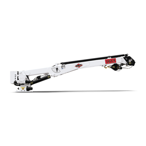
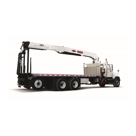
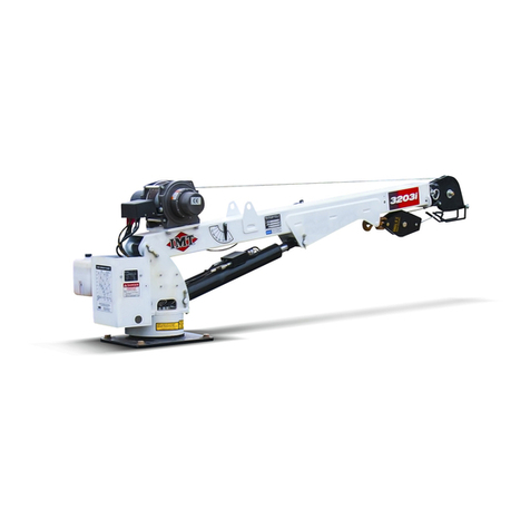
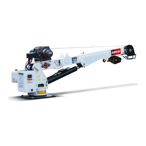
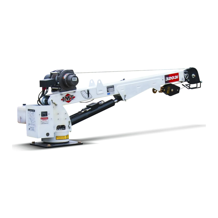
IMT 2003i User manual

Manual # 99904385
IMT 2003i Technical
Specifications & Parts
Revised: March 13, 2017
IOWA MOLD TOOLING CO., INC.
PO Box 189
Garner, IA 50438
Tel: 641-923-3711 FAX: 641-923-2424
Website: http://www.imt.com
Copyright © 2017 Iowa Mold Tooling Co., Inc.
All rights reserved
No part of this publication may be reproduced, stored in a retrieval system, or transmitted in any
form or by any means, electronic, mechanical, photocopying, recording or otherwise without the
prior written permission of Iowa Mold Tooling Co., Inc.
Iowa Mold Tooling Co., Inc. is an Oshkosh Corporation Company.


i
Contents
Revisions .................................................................................................................................................... iii
Introduction 5
Safety 7
Safety Instructions ........................................................................................................................................8
Daily Safety Inspection...............................................................................................................................10
Electrical Hazards.......................................................................................................................................11
Crane Capacity............................................................................................................................................14
2003i Capacity Chart..................................................................................................................................15
Electric Crane Danger Decal Placement.....................................................................................................16
Work Site Planning.....................................................................................................................................18
Stabilizer Operation....................................................................................................................................19
Ground Support ..........................................................................................................................................20
Winch Safety ..............................................................................................................................................20
Operation 21
Electric Crane Start-up and Task Performance...........................................................................................21
Tethered Remote Handle Operating Instructions........................................................................................23
Crane Shut Down........................................................................................................................................24
Operation in Poor Conditions.....................................................................................................................25
Hand Signals...............................................................................................................................................25
Maintenance & Repair 27
Maintenance Introduction...........................................................................................................................27
Electric Crane Power Safety.......................................................................................................................28
Maintenance Schedule................................................................................................................................28
Electric Crane Lubrication..........................................................................................................................29
Grease Zerks...............................................................................................................................................29
Pin Removal & Inspection..........................................................................................................................30
Electric Crane Wear Pads...........................................................................................................................31
Wire Rope Inspection .................................................................................................................................32
Wire Rope Lubrication ...............................................................................................................................33
Wire Rope Maintenance .............................................................................................................................33
Wire Rope Inspection & Replacement........................................................................................................33
Additional Inspections................................................................................................................................34
Technical Specifications 37
2003i Technical Data..................................................................................................................................38
2003i Capacity Chart..................................................................................................................................39
2003i Geometric Configuration & Mounting Pattern.................................................................................40

ii Contents
Crane Reference 41
2003i Assemblies & Grease Zerk Locations...............................................................................................42
2003i Recommended Spare Parts ...............................................................................................................43
Electric Crane Control................................................................................................................................44
Parts 45
Parts Information ........................................................................................................................................46
Crane Assembly & Complete Parts List (99904352-1) ..............................................................................48
Base & Mast Assembly (99904352-2) (See Parts List for Effectivity Dates).............................................50
Base & Mast Assembly (99904352-2) (See Parts List for Effectivity Dates).............................................52
Boom Assembly (99904352-3)...................................................................................................................54
Electrical Box & Gear Guard (99904352-4)...............................................................................................55
Boom, Winch, & Crane Assembly (99904352-5).......................................................................................56
Electrical Installation (99904398)...............................................................................................................58
Electric Crane Battery Circuit (99904884).................................................................................................59
Winch (71570921) (Eff 2-09).....................................................................................................................60
Winch (71570875) (Through 2-09) ............................................................................................................61
Handle Assembly, Tethered Remote (51721683).......................................................................................63
Turntable Gear (71056635).........................................................................................................................65
Decal Kit (95721546) .................................................................................................................................67
General Reference 69
Inspection Checklist....................................................................................................................................69
Deficiency / Recommendation / Corrective Action Report ........................................................................74
Thread Torque Chart (English)...................................................................................................................76
Thread Torque Chart (Metric) ....................................................................................................................77
Turntable Bearing Thread Tightening Sequence ........................................................................................78
Turntable Bearing Inspection......................................................................................................................79
Turntable Bearing Tilt Test.........................................................................................................................80

Contents iii
Revisions
DATE LOCATION DESCRIPTION
20090312
THROUGHOUT
ADDED COMPONENT SPARE PARTS, UPDATED ELECTRICAL KIT,
ASSEMBLIES.
20100427
99904884
ADDED BATTERY CIRCUIT DRAWING.
20100615
SPECS.
CORRECTED ELECTRICAL INSTALLATION REQUIREMENTS
20100812
71570921
ADDED 71570921 WINCH PARTS
20111117
ECN 11628 - EDIT STABILIZER WORDING, UPDATE DECALS.
20131120
99904352-2
ECN 12043 & 11974
20140909
GREASING
INSTRUCTIONS
ECN 12264 – MOLUB-ALLOY 882 WAS MOLUB-ALLOY 936
20170313
70392399
CN:519:Updated to new grease info


5
GENERAL
This manual will help you operate your IMT crane correctly and safely. The manual does not
replace any government regulations, safety codes or insurance carrier requirements. Read and
understand the manual and all safety procedures for this crane prior to operation.
WARNING
Failure to read, understand and follow any
safety procedures for this equipment may
result in death, serious injury or equipment
damage.
Use caution and common sense. Refer to ANSI/ASME B30.5, the standard for Telescoping and
Mobile Boom Cranes, for more information on crane design and test criteria. (Contact the
American Society of Mechanical Engineers at www.asme.org for information on ANSI/ASME
B30.5.) Crane operators must also be familiar with OSHA 29CFR, Subpart N, Article 1926.550
and CAL-OSHA Title 8, Article 93 (California).
CRANE AND SAFETY EQUIPMENT MODIFICATIONS
Do not modify your crane with anything other than IMT approved equipment. If in doubt, contact
IMT prior to making modifications. DO NOT alter or modify any safety device! All safety devices
must be inspected, tested and maintained in proper working condition.
Decals regarding crane safety and operation are safety equipment and must be maintained.
Decals must be kept clean and legible.
OWNER RESPONSIBILITIES
You must maintain and operate this unit for the safest working conditions possible. You must
follow existing Federal, State, and Local codes and regulations governing the safe use and
maintenance, and must make sure anyone involved in equipment operation understands how to
operate and maintain the crane safely. Contact IMT or your IMT distributor for clarification.
WARRANTY
The equipment warranty on this unit will be void on any part of the unit subjected to misuse due
to overloading, abuse, lack of maintenance and unauthorized modifications. No warranty -
verbal, written or implied - other than the official, published IMT new machinery and equipment
warranty is valid with this unit.
CHAPTER 1
Introduction

6 IMT 2003i Technical Specifications & Parts Manual # 99904385
MANUAL STRUCTURE
Throughout the manual, NOTEs, CAUTIONs, WARNINGs and DANGERs are used to draw the
attention of personnel. They are defined as follows:
NOTICE TO THE OWNER / USER
If the crane is involved in a property damage accident, contact your IMT distributor immediately
and provide them with the details of the accident and the serial number of the equipment. If an
accident involves personal injury, immediately notify your distributor and IMT Technical Support
at:
IOWA MOLD TOOLING CO., INC.
500 HWY 18 WEST
GARNER, IA 50438
641 - 923 - 3711
CAUTION
ACAUTION is used when there is the
very strong possibility of damage to the
equipment or premature equipment
failure.
WARNING
A WARNING is used when there is the
potential for personal injury or death.
NOTE
ANOTE is used to either convey
additional information or to provide
further emphasis for a previous point.
DANGER
Danger indicates an imminently hazardous
situation which, if not avoided, will result
in death or serious injury. Danger is used
in the most extreme situations.

7
In This Chapter
Safety Instructions....................................................................8
Daily Safety Inspection............................................................. 9
Electrical Hazards ....................................................................11
Crane Capacity ........................................................................14
Electric Crane Danger Decal Placement .................................. 16
Work Site Planning................................................................... 18
Stabilizer Operation..................................................................19
Ground Support........................................................................20
Winch Safety............................................................................ 20
CHAPTER 2
Safety

8 IMT 2003i Technical Specifications & Parts Manual # 99904385
Safety Instructions
WARNING
Keep children, by-standers, and persons not
required in the operation of equipment at
least 10’-0” (3.05 m) from the outermost
range of the crane.
SAFE CRANE OPERATION
Do NOT operate crane unless you have been trained in safe operation.
Read, understand, and follow manual, labels, safety instructions, and your employer’s work
rules.
Make sure guards, safety signs, and safety features are in place and in good condition.
Read, understand and follow the crane load and work area charts. Do not exceed crane or
winch ratings.
Keep three wraps of loadline on winch.
Operate crane controls slowly and smoothly.
Know the position of the booms at all times while operating the crane. Eliminate swing by
positioning the boom tip directly over the center of the load before lifting.
Do NOT operate in excessive wind speeds.
Keep load under boom tip. Do NOT side load boom, drag, or swing loads.
Stow boom and stabilizers before traveling.
Do not allow anyone to ride crane boom, hook, or load.
Follow all inspections and maintenance practices listed in manuals.
ELECTRICAL SYSTEM
This crane operates using electrical power from the vehicle battery.
DANGER
Avoid electrocution! Do NOT work on the
crane before turning off the crane power
supply in the crane cabinet and removing
the crane power disconnectcable from
the vehicle battery.

Chapter 2 Safety 9
STABILITY
Use crane on solid, level surface with stabilizers properly extended, and keep vehicle level.
Reduce loads when operating on uneven ground. Keep personnel clear of moving stabilizers.
When you rotate the crane, the load may change from being supported by the stabilizers to the
vehicle suspension. Be cautious as you rotate the crane, because the springs on the carrier
vehicle will respond differently to the load than the tires will.
WINCH
Never use the winch to drag a load into position before lifting. This may sideload the crane or
stress the wire rope beyond safe limits. Equipment damage may result.
When using a winch, always keep the tip of the extension boom as close to the load as practical.
This will prevent the load from swinging out of control when using the rotation (swing) function.
DANGER
DO NOT permit personnel to ride the
boom, loadline, hook or load, as this
action may cause DEATH or serious injury.
Use only specified wire rope for lifting. Retain at least three full wraps of wire rope on the winch
drum at all times.
WIRE ROPE
Before extending the boom, always pay out the wire rope. Failure to do so may overstress the
wire rope and cause a two block condition.

10 IMT 2003i Technical Specifications & Parts Manual # 99904385
Daily Safety Inspection
Use the Crane Log, IMT Manual No. 99900686, the inspection checklist in the reference section
of this manual, or the following list when inspecting your unit at start-up and during operation:
1 Vehicle - Check oil level, battery, lights, brakes, and tires for inflation, pressure, cuts, and
loose or missing wheel lugs.
2 Safety Accessories - Check for proper function, oil levels, leaks and malfunctions.
3 Hydraulic Oil Reservoir - Check for proper oil level, leaks and blockages.
4 Weldments - Check visually for damage, especially cracks or breaks in welds.
5 Cylinders - Check for leakage and scored rods.
6 Fasteners - Check pins, sheaves, nuts and bolts for breakage, excessive wear and
tightness.
7 Crane Hooks - Check for the presence of a safety catch, twists, cracks, or damage.
8 Ropes & Slings - Check for frayed edges, broken strands, kinks, flat spots, and end
attachments.
9 Covers and Guards - Check for missing or improperly maintained covers and guards.
10 Operation Placards and Safety Decals - Check for illegible or missing decals and placards.
Refer to the decal section of this manual for more information on the required decals.
Replace or repair any items as needed prior to equipment operation.

Chapter 2 Safety 11
Electrical Hazards
DANGER
ELECTROCUTION HAZARD
Vehicle is not insulated.
Do NOT raise boom into power lines.
Look up and use light to search for power lines in the dark.
Keep boom and vehicle a minimum of 20 ft. (6.1 m) away from power lines.
Do not step off a charged vehicle.
If you touch a charged vehicle while standing on the ground, you will die.
Overhead power lines are not insulated. While some lines have a weather covering and appear
to be insulated, they are not. The vehicle or parts of the vehicle do not need to touch the power
line for the vehicle to become energized. Electricity will arc across gaps, and all overhead wires
or cables should be considered hazardous and dangerous. Always operate the crane so that no
part of the crane or load enters the "Danger Zone", the minimum clearance distance for a
powerline.
DANGER
VOLTAGE HAZARD
The danger zone of a particular powerline is based on its voltage. High voltage levels increase
the danger zone. See figure.
DANGER ZONE
AVOID THIS AREA.
DANGER ZONE FOR CRANES
OPERATING NEAR ELECTRICAL
POWERLINES

12 IMT 2003i Technical Specifications & Parts Manual # 99904385
70394445
DANGER
Electrocution Hazard
Never approach this vehicle or the
load if it is near power lines.
Death or serious injury will result from
touching or being near this vehicle if it
becomes charged.
REQUIRED CLEARANCE OF CRANES FROM ELECTRICAL TRANSMISSION LINES
NORMAL VOLTAGE
kV (Phase to Phase)
MINIMUM CLEARANCE
REQUIRED Feet (meters)
OPERATION NEAR HIGH
VOLTAGE POWERLINES
From 0 to 350
20 (6.10)
Above 350 or unknown
50 (15.24)
OPERATION IN TRANSIT WITH
NO LOAD AND BOOM OR MAST
LOWERED
From 0 to 0.75
4 (0.22)
From 0.75 to 50
6 (0.83)
From 50 to 345
10 (3.05)
From 345 to 750
16 (4.87)
From 750 to 1000
20 (8.10)
GUIDELINES WHEN WORKING AROUND POWER LINES:
Make sure the work area is clear of major obstacles and overhead obstructions
Do not work within 20 feet (6.10 m) of high-voltage lines energized up to 35,000 volts, and
50 feet (15.24 m) of high-voltage lines energized up to 50,000 volts or of unknown voltage. It
is the law. The operator can be liable if activities in violation of this law cause injury or
property damage.
Only operate in conditions where the vehicle and equipment can be stabilized. Do not set up
or operate on soft soil, mud, snow or other unstable ground conditions that could allow the
vehicle or equipment to shift and move within 20 feet (6.10 m) of a power line.
Look up and live. Always check the operating vicinity for power lines before you drive into it.
Tree branches can hide power lines or cables from view. If operating at night, use powerful
lights to search for power lines or poles.
During windy conditions, allow additional clearance.
Do not rely on cage-type boom guards, insulating links, or proximity warning devices for
safety. Adhere to the required distances listed in table titled REQUIRED CLEARANCE OF
CRANES FROM ELECTRICAL TRANSMISSION LINES.

Chapter 2 Safety 13
Contact the utility company before beginning work near powerlines.
Always assume overhead lines to be energized.
Avoid transporting a crane over uneven terrain.
When using rope to steady a load or restrain spinning of the load, be aware that rope will
also conduct electricity, especially if wet or damp.
Reduce operating speed when in close proximity to powerlines in order to allow the operator
more reaction time.
IF ELECTRICAL CONTACT OCCURS:
1 If you are on or inside a vehicle that contacts or is energized by a power line, stay where you
are. Exiting the vehicle is more hazardous than remaining inside. Unless there is a fire, it is
safer to stay in the vehicle than to attempt an exit. Stay in or on the vehicle until a power
company representative informs you that the line has been de-energized and grounded and
that the area is safe.
2 If it is critical that you leave the vehicle, JUMP as far away as possible landing with both feet
together. Maintain balance or fall forward, don’t fall back towards the vehicle which could
result in the body becoming a pathway between the vehicle and the ground. No part of your
body should touch the vehicle and the ground at the same time.
3 If you are outside of the vehicle that contacts or is energized by a power line, move away
from the vehicle and stay away. Warn others to stay away. You are safe from electrical
shock as long as you do not become a pathway for current to flow to the ground. Do not
approach the vehicle until a power company representative informs you that the line has
been de-energized and grounded and that the area is safe
4 In certain circumstances the ground around a charged vehicle or downed power line may be
energized. The ground becomes charged in concentric circles around the vehicle with
varying voltage potential. Straddling these bands can result in serious injury or death as the
current passes through your body. Stay away from the vehicle or power line, keeping both
feet on the ground at the same time. This will prevent you from becoming a conductor
between two areas of the ground that are charged differently.
5 If someone is trapped inside a vehicle that has come in contact with a power line, instruct
them to stay inside and not to try to exit, unless their life is in eminent danger or a fire is
present. Call 911 immediately and instruct the 911 operator to contact the power company.
The power company personnel are trained to eliminate the hazard by de-energizing the line.
6 Do not attempt any rescue a person on or inside an energized vehicle, or who is energized
themselves. If you touch someone whose body is conducting current, the current will flow
through you too. Your muscles will seize up and you will not be able to escape.
ELECTRICAL CONTACT FOLLOW-UP:
1 Inspect and repair any equipment affected by electrical contact.
2 Replace any wire rope which has had high voltage contact.

14 IMT 2003i Technical Specifications & Parts Manual # 99904385
Crane Capacity
The IMT crane is designed to lift specific loads. These loads are defined on the capacity placard
mounted near the operator’s station and on the crane. Exceeding the limits presented on the
capacity placard will create severe safety hazards and will shorten the life of the crane. The
operator and other concerned personnel must know the load capacity of the crane and the
weight of the load being lifted!
The capacity chart for each model is located in the specific crane technical specifications manual
and on placards on the crane and body.
WARNING
Never exceed the crane’s rated load
capacities. Doing so will cause structural
damage towinchesand cables which can
lead todeath or seriousinjury.
NOTE
Capacity Placards are intentionally located
nearthe operator to assure ready reference
in determining when a load can or cannot be
handled.
Load limit information on the capacity
placards is formulated on 85%of tipping.
Tipping refers tothe crane actuallytipping
with its opposite stabilizer and tireshaving
broken contact with the surface.
Prior to lifting a load:
1 Determine the weight of the load.
2 Determine the weight of any load handling devices.
3 Add the weight of the load and the weight of the load handling devices. The sum is the total
weight of the load being lifted.
4 Determine the distance from the centerline of crane rotation to the centerline of the load
being lifted.
5 Determine the distance from the centerline of crane rotation to the centerline of where the
load is to be moved to.
6 The actual distance used should be figured as the larger of items 4 and 5 above.

Chapter 2 Safety 15
2003i Capacity Chart
2003i CAPACITY CHART
Weight of load handling devices are part of the load
lifted and must be deducted from the capacity.
IOWA MOLD TOOLING CO., INC.
BOX 189, GARNER, IA 50438-0189
TEL: 641-923-3711 FAX: 641-923-2424
70397481
15°
30°
45°
0
(CL)
1'
(.31 m)
2'
(.61 m)
3'
(.91 m)
4'
(1.2 m)
5'
(1.5 m)
6'
(1.8 m)
7'
(2.1 m)
1'
(.31 m)
2'
(.61 m)
3'
(.91 m)
4'
(1.2 m)
5'
(1.5 m)
6'
(1.8 m)
0
(Short Base)
LIFTING CAPACITY
IS 2,000 LB (907 kg)
AT ALL LOCATIONS.

16 IMT 2003i Technical Specifications & Parts Manual # 99904385
Electric Crane Danger Decal Placement
10'
3.0m
12'
3.6m
14'
4.2m
16'
4.8m
0
75°
60°
45°
30°
15°
2'
0.6m
4
'
1.2m
8
'
2.4m
0
(Base)
6'
1.8m
DISTANCE IN FEET/METERS/ LOAD IN POUNDS/KG .
Maximum 1-part line
capacityis 2000 lb.
For greater loads, use
2-part line.
NOTE: Boxes denote
2-part line.
4000
18153050
13852460
1115
2140
970
3135
1420
2350
10651450
660
1990
905
1575
715
1350
615
1195
540
1140
520
975
440
850
385
1905
865
1670
755 1050
475 730
330
LB
K
G
10'
3.0m
12'
3.6m
14'
4.2m
2'
0.6m
4'
1.2m
8'
2.4m
6'
1.8m
70395090
DANGER
70394443
FREE FALLING
MANUALBOOM EXTENSION(S)
WILLCAUSE
DEATH OR SERIOUS INJURY
•
•
•
To avoid winch
unspooling, use single
line downhaul weight
with single line. Be
sure to install weight
below locking collar.
LOCKING
COLLAR
DOWNHAUL
WEIGHT
71394083
Unplug remote pendant and store
in tool box or cab when not in use.
NOTICE:
GREASE
WEEK LY
703974 11
70397412
GREASE
WEEK LY
70397404
AVOID DEATH OR
SERIOUS INJURY
Before beginning any work on
crane,
• Turn OFF crane power supply in
crane cabinet.
•Remove crane power disconnect
cable from vehicle battery.
Weekly, remove coverand lubricate with
IMT recommended
open-gearcompound while rotating crane.
IMT part number: 89086244
70392399

Chapter 2 Safety 17
Additional danger decals are applied inside the truck body door. These decals include the
following.
DISTANCE IN FEET/ METERS / LOAD IN POUNDS / KG
Follow Safe Operating & Inspection Procedures
Electrocution Hazard
Crane and remote control are not insulated.
70396613
Falling Load Hazard
Death or serious injury will result from approaching or contacting a power line.
Falling loads may injure or kill.
Fall Hazard
Riding on boom, hook, or loadline may injure or kill.
Overload Hazard
Overloading the crane may injure or kill.
WARNING
Weight of load handling devices are part of the load lifted
and must be deducted from the capacity.
There are two warning decals applied to the front, sides and rear of the carrier vehicle.

18 IMT 2003i Technical Specifications & Parts Manual # 99904385
Work Site Planning
LOAD DOES
NOT EXCEED
CRANE
CAPACITY.STABILIZERS ARE FULLY OUT ANDDOWN
ON A FIRM AND LEVEL SURFACE.
NO OVERHEAD OBSTRUCTIONS.
NO POWERLINES
PARKING BRAKE
"ON."
TRANSMISSION
IN NEUTRAL.
Lift safety depends on work site preparation. Plan your lifts carefully. Consider:
Powerlines
Bystanders
Overhead obstructions
Solid surface support
Determine the weight of the load to be lifted. Use the crane capacity chart to make sure all lifts
are performed within the rated capacity of the crane. Position the carrier vehicle with these
capacities in mind and avoid any overhead obstructions which can impair the lift.
DANGER
AVOID POWER LINES! Read and
understand the Electrical Hazard section
of this manual before attempting any
crane operations nearpowerlines.
Position the carrier vehicle so that when the crane is fully extended it can't contact electrically
charged lines or apparatus. Twenty feet (6.10 meters) is the minimum distance that any portion
of the crane, loadline or load can be to electrical lines carrying up to 35,000 volts. Allow 50 feet
(15.24 m) minimum for powerlines with unknown voltages, or with voltages above 35,000 volts.
In windy conditions, allow extra space for powerline and loadline sway and deflection. Provide
additional clearance between the crane and electrical lines. If the powerline or apparatus
voltage is not known, contact the electrical utility prior to the lift.
If a lift is impossible to perform within the minimum distance between electrical source and
crane, ask the power company to de-energize the powerlines or apparatus before any lift is
attempted.
Use a qualified signal person or spotter when working near electrical sources, even if the
powerline has been de-energized.
Other manuals for 2003i
1
Table of contents
Other IMT Construction Equipment manuals
Popular Construction Equipment manuals by other brands

Mauldin
Mauldin 550-E Operation manual

Amco Veba
Amco Veba 601T WARNING, OPERATING AND MAINTENANCE MANUAL

Skylift
Skylift Mini-Derrick Super 6000 Low Pro Parts and maintenance manual
Atlas Copco
Atlas Copco SmartROC T45--10 instructions
MQ Multiquip
MQ Multiquip MVH308GH manual
HYVA
HYVA HC801 WARNING, OPERATING AND MAINTENANCE MANUAL
Case
Case 3550 Operator's manual

Ammann
Ammann ARX 23-2 operating manual

Hailo
Hailo Fast & Lock 7 quick start guide
HEIN-WERNER AUTOMOTIVE
HEIN-WERNER AUTOMOTIVE HW93809 Operating instructions & parts manual

Mikasa
Mikasa MVC-F60H operating instructions
Manitowoc
Manitowoc Grove GMK 5250L operating instructions

